

Page 1
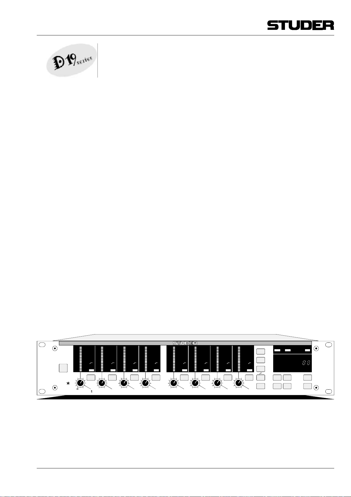
D19 MicAD
8-Channel Mic/Line Preamplifier
with Digital Outputs
Betriebsanleitung
Operating Instructions
MicAD
POWER
MIC
LINE
OVL
-1
-3
-6
-9
-12
-18
-24
-30
-40
-60
12
18
dBu/FS
LINE
OVL
-1
-3
-6
MIC
-9
-12
LINE
-18
Ø
-24
48V
-30
-40
-60
SEL
6
12
0
18
-6
24
dBu/FS
LINE
OVL
-1
-3
-6
MIC
-9
-12
LINE
-18
Ø
-24
48V
-30
LINK
-40
-60
SEL SEL SEL
6
12
0
18
-6
24
dBu/FS
2 3
LINE
OVL
-1
-3
-6
MIC
-9
-12
LINE
-18
Ø
-24
48V
-30
-40
-60
6
0
-6
6
12
18
-6
24
dBu/FS
LINE
OVL
-1
-3
-6
MIC
-9
-12
LINE
-18
Ø
-24
48V
-30
LINK
-40
-60
12
18
0
24
dBu/FS
4 5
LINE
OVL
-1
-3
-6
MIC
-9
-12
LINE
-18
Ø
-24
48V
-30
-40
-60
SEL SEL SEL SEL
6
12
0
18
-6
24
dBu/FS
LINE
MIC
LINE
Ø
48V
LINK
6
0
18
-6
6 7
OVL
-1
-3
-6
-9
-12
-18
-24
-30
-40
-60
12
24
dBu/FS
LINE
Prepared and edited by:
STUDER Professional Audio AG
Technical Documentation
Althardstrasse 30
CH-8105 Regensdorf - Switzerland
STUDER is a registered trade mark of STUDER Professional Audio AG, Regensdorf
OVL
-1
-3
-6
MIC
-9
-12
LINE
-18
Ø
-24
48V
-30
-40
-60
6
12
0
18
-6
24 -6
dBu/FS
LINE
MIC/LINE
MIC
LINE
Ø
Ø
48V
48V
LINK
6
STEREO LINK
0
PEAK HOLD SOFT CLIP REMOTE
8
D19 SERIES
HOLD SOFT REM
48
INT
44
WCLK
16DI
VAR
AES
16NS
AUTO
20BIT
MODE SYNC CTRL CH
Copyright by STUDER Professional Audio AG
Printed in Switzerland
Order no. 10.27.3781 (Ed. 0996)
Subject to change
Page 2
SAFETY / SECURITE / SICHERHEIT
To reduce the risk of electric shock, do not remove covers (or back).
No user-serviceable parts inside. Refer servicing to qualified service
personnel.
Afin de prévenir un choc électrique, ne pas enlever les couvercles (où
l’arrière) de l’appareil. Il ne se trouve à l’intérieur aucune pièce pouvant être réparée par l’usager.
Um die Gefahr eines elektrischen Schlages zu vermeiden, entfernen Sie keine Geräteabdeckungen (oder die Rückwand). Überlassen Sie Wartung und Reparatur qualifiziertem Fachpersonal.
This symbol is intended to alert the user to presence of uninsulated
“dangerous voltage” within the apparatus that may be of sufficient
magnitude to constitute a risk of electric shock to a person.
Ce symbole indique à l'utilisateur qu'il existent à l'intérieur de l'appareil des “tensions dangereuses”. Ces tensions élevées entrainent
un risque de choc électrique en cas de contact.
Dieses Symbol deutet dem Anwender an, dass im Geräteinnern die
Gefahr der Berührung von “gefährlicher Spannung” besteht. Die
Grösse der Spannung kann zu einem elektrischen Schlag führen.
This symbol is intended to alert the user to the presence of important
instructions for operating and maintenance in the enclosed documentation.
Ce symbole indique à l’utilisateur que la documentation jointe contient d'importantes instructions concernant le fonctionnement et la
maintenance.
Dieses Symbol deutet dem Anwender an, dass die beigelegte Dokumentation wichtige Hinweise für Betrieb und Wartung enthält.
CAUTION: Lithium battery. Danger of explosion by incorrect handling. Replace
by battery of the same make and type only.
ATTENTION: Pile au lithium. Danger d'explosion en cas de manipulation incorrec-
te. Ne remplacer que par un modèle de même type.
ACHTUNG: Explosionsgefahr bei unsachgemässem Auswechseln der Lithium-
batterie. Nur durch den selben Typ ersetzen.
ADVARSEL: Lithiumbatterei. Eksplosinsfare. Udskinftning ma kun foretages af en
sagkyndig of som beskrevet i servicemanualen (DK).
I
Page 3

SAFETY / SECURITE / SICHERHEIT
FIRST AID
(in case of electric shock)
1. Separate the person as quickly as
possible from the electric power
source:
• by switching off the equipment
• or by unplugging or disconnecting
the mains cable
• pushing the person away from the
power source by using dry insulating material (such as wood or
plastic).
• After having sustained an elec-
tric shock, always consult a
doctor.
WARNING!
DO NOT TOUCH THE PERSON
OR HIS CLOTHING BEFORE
THE POWER IS TURNED OFF,
OTHERWISE YOU STAND THE
RISK OF SUSTAINING AN
ELECTRIC SHOCK AS WELL!
PREMIERS SECOURS
(en cas d'électrocution)
1. Si la personne est dans l'impos-
sibilité de se libérer:
• Couper l'interrupteur principal
• Couper le courant
• Repousser la personne de l'appareil à l'aide d'un objet en matière
non conductrice (matière plastique ou bois)
• Après une électrocution, toujours
consulter un médecin.
ATTENTION!
NE JAMAIS TOUCHER UNE
PERSONNE QUI EST SOUS
TENSION, SOUS PEINE DE
SUBIR EGALEMENT UNE
ELECTROCUTION.
ERSTE HILFE
(bei Stromunfällen)
1. Bei einem Stromunfall die be-
troffene Person so rasch wie
möglich vom Strom trennen:
• Ausschalten des Gerätes
• Ziehen oder Unterbrechen der
Netzzuleitung
• Betroffene Person mit isoliertem
Material (Holz, Kunststoff) von
der Gefahrenquelle wegstossen
• Nach einem Stromunfall sollte
immer ein Arzt aufgesucht werden.
ACHTUNG!
EINE UNTER SPANNUNG STEHENDE PERSON DARF NICHT
BERÜHRT WERDEN. SIE KÖNNEN DABEI SELBST ELEKTRISIERT WERDEN!
2. If the person is unconscious:
• check the pulse,
• reanimate the person if respiration
is poor,
• lay the body down, turn it to one
side, call for a doctor immediately.
2. En cas de perte de connaissance
de la personne électrocutée:
• Controller le pouls
• Si nécessaire, pratiquer la respiration artificielle
• Placer l'accidenté sur le flanc et
consulter un médecin.
2. Bei Bewusstlosigkeit des Verun-
fallten:
• Puls kontrollieren,
• bei ausgesetzter Atmung künstlich beatmen,
• Seitenlagerung des Verunfallten
vornehmen und Arzt verständigen.
II
Page 4
SICHERHEIT / SAFETY
Installation
Vor der Installation des Gerätes müssen die hier aufgeführten und auch die weiter in dieser Anleitung mit
bezeichneten Hinweise gelesen und während der Installation und des Betriebes beachtet werden.
Untersuchen Sie das Gerät und sein Zubehör auf allfällige
Transportschäden.
Ein Gerät, das mechanische Beschädigung aufweist oder
in welches Flüssigkeit oder Gegenstände eingedrungen
sind, darf nicht ans Netz angeschlossen oder muss sofort
durch Ziehen des Netzsteckers vom Netz getrennt werden.
Das Öffnen und Instandsetzen des Gerätes darf nur von
Fachpersonal unter Einhaltung der geltenden Vorschriften
durchgeführt werden.
Falls dem Gerät kein konfektioniertes Netzkabel
beiliegt, muss dieses durch eine Fachperson unter
Verwendung der mitgelieferten Kabel-Gerätedose
IEC320/C13 oder IEC320/C19 und unter Berücksichtigung der einschlägigen, im geweiligen Lande geltenden
Bestimmungen angefertigt werden; siehe unten.
Vor Anschluss des Netzkabels an die Netzsteckdose muss
überprüft werden, ob die Stromversorgungs- und Anschlusswerte des Gerätes (Netzspannung, Netzfrequenz)
innerhalb der erlaubten Toleranzen liegen. Die im Gerät
eingesetzten Sicherungen müssen den am Gerät angebrachten Angaben entsprechen.
Ein Gerät mit einem dreipoligen Gerätestecker (Gerät der
Schutzklasse I) muss an eine dreipolige Netzsteckdose
angeschlossen und somit das Gerätegehäuse mit dem
Schutzleiter der Netzinstallation verbunden werden (Für
Dänemark gelten Starkstrombestimmungen, Abschnitt
107).
Installation
Before you install the equipment, please read and adhere
to the following recommendations and all sections of these
instructions marked with .
Check the equipment for any transport damage.
A unit that is mechanically damaged or which has been
penetrated by liquids or foreign objects must not be connected to the AC power outlet or must be immediately
disconnected by unplugging the power cable. Repairs must
only be performed by trained personnel in accordance with
the applicable regulations.
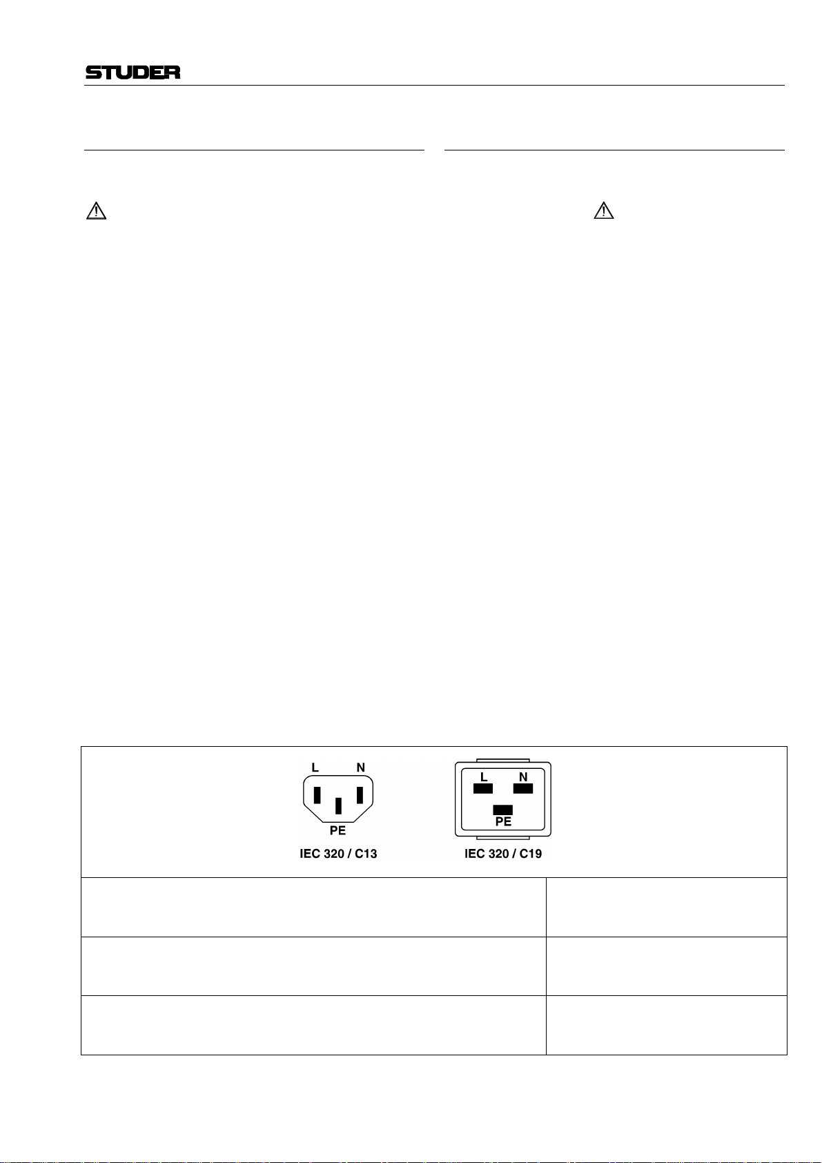
Should the equipment be delivered without a matching
mains cable, the latter has to be prepared by a trained
person using the attached female plug (IEC320/C13 or
IEC320/C19) with respect to the applicable regulations in
your country - see diagram below.
Before connecting the equipment to the AC power outlet,
check that the local line voltage matches the equipment
rating (voltage, frequency) within the admissible tolerance. The equipment fuses must be rated in accordance with
the specifications on the equipment.
Equipment supplied with a 3-pole appliance inlet (equipment conforming to protection class I) must be connected
to a 3-pole AC power outlet so that the equipment cabinet
is connected to the protective earth conductor of the AC
supply (for Denmark the Heavy Current Regulations,
Section 107, are applicable).
Female plug (IEC320), view from contact side:
L live; brown National American Standard: Black
N neutral; blue White
PE protective earth; green and yellow green
Connecteur femelle (IEC320), vue de la face aux contacts:
L phase; brun Standard national américain: Noir
N neutre; bleu Blanc
PE terre protective; vert et jaune Vert
Ansicht auf Steckkontakte der Kabel-Gerätesteckdose (IEC320):
L Phase; braun USA-Standard: Schwarz
N Nulleiter; blau Weiss
PE Schutzleiter; gelb/grün grün
III
Page 5
SICHERHEIT / SAFETY
Zugentlastung für den Netzanschluss
Zum Verankern von Steckverbindungen ohne mechanische
Verriegelung (z.B. IEC-Kaltgerätedosen) empfehlen wir
die folgende Anordnung:
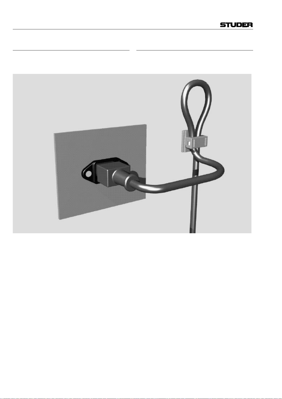
Mains connector strain relief
For anchoring connectors without a mechanical lock (e.g.
IEC mains connectors), we recommend the following arrangement:
Vorgehen: Der mitgelieferte Kabelhalter ist selbstklebend.
Bitte beachten Sie bei der Montage die folgenden Regeln:
1. Der Untergrund muss sauber, trocken und frei von Fett,
Öl und anderen Verunreinigungen sein. Temperaturbereich für optimale Verklebung: 20...40° C.
2. Entfernen Sie die Schutzfolie auf der Rückseite des
Kabelhalters und bringen sie ihn mit kräftigem Druck
an der gewünschten Stelle an. Lassen sie ihn unbelastet
so lange wie möglich ruhen – die maximale Klebekraft
ist erst nach rund 24 Stunden erreicht.
3. Die Stabilität des Kabelhalters wird erhöht, wenn Sie
ihn zusätzlich verschrauben. Zu diesem Zweck liegen
ihm eine selbstschneidende Schraube sowie eine M4Schraube mit Mutter bei.
4. Legen Sie das Kabel gemäss Figur in den Halter ein
und pressen Sie die Klemme kräftig auf, bis das Kabel
fixiert ist.
Procedure: The cable clamp shipped with your unit is
auto-adhesive. If mounting, please follow the rules below:
1. The surface to be adhered to must be clean, dry, and
free from grease, oil or other contaminants. Best application temperature range is 20...40° C.
2. Remove the plastic protective backing from the rear
side of the clamp and apply it firmly to the surface at
the desired position. Allow as much time as possible
for curing. The bond continues to develop for as long
as 24 hours.
3. For improved stability, the clamp can be fixed with a
screw. For this purpose, a self-tapping screw and an
M4 bolt and nut are included.
4. Place the cable into the clamp as shown in the illustr a-
tion above and firmly press down the internal top cover
until the cable is fixed.
IV
Page 6

UMGEBUNGSBEDINGUNGEN / AMBIENT CONDITIONS
Lufttemperatur und Feuchtigkeit
Allgemein
Die Betriebstauglichkeit des Gerätes oder Systems ist unter
folgenden Umgebungsbedingungen gewährleistet:
EN 60721-3-3, Set IE32, Wert 3K3.
Diese Norm umfasst einen umfassenden Katalog von Parametern; die wichtigsten davon sind: Umgebungstemperatur
+5...+40 °C; rel. Luftfeuchtigkeit 5...85% – d.h. weder Kondensation noch Eisbildung; abs. Luftfeuchtigkeit 1...25 g/m³; Temperatur-Änderungsrate < 0,5 °C/min. In den folgenden Abschnitten wird darauf näher eingegangen.
Unter den genannten Bedingungen startet und arbeitet das
Gerät oder System problemlos. Ausserhalb dieser Spezifikationen möglicherweise auftretende Probleme sind in den folgenden
Abschnitten beschrieben.
Umgebungstemperatur
Geräte und Systeme von Studer sind allgemein für einen Umgebungstemperaturbereich (d.h. Temperatur der eintretenden
Kühlluft) von +5...+40 °C ausgelegt. Bei Installation in einem
Schrank muss der vorgesehene Luftdurchsatz und dadurch die
Konvektionskühlung gewährleistet sein. Folgende Tatsachen
sind dabei zu berücksichtigen:
1. Die zulässige Umgebungstemperatur für den Betrieb der
Halbleiter-Bauelemente beträgt 0 °C bis +70 °C (commercial
temperature range for operation).
2. Der Luftdurchsatz der Anlage muss gewährleisten, dass die
austretende Kühlluft ständig kühler ist als 70 °C.
3. Die mittlere Erwärmung der Kühlluft soll 20 K betragen,
die maximale Erwärmung an den heissen Komponenten darf
somit um weitere 10 K höher liegen.
4. Zum Abführen einer Verlustleistung von 1 kW bei dieser
zulässigen mittleren Erwärmung ist eine Luftmenge von
2,65 m³/min notwendig.
Beispiel: Für ein Rack mit einer Leistungsaufnahme P = 800 W
ist eine Kühlluftmenge von 0,8 * 2,65 m³/min nötig, entsprechend 2,12 m³/min.
5. Soll die Kühlfunktion der Anlage (z.B. auch bei LüfterAusfall oder Bestrahlung durch Spotlampen) überwacht werden, so ist die Temperatur der Abluft unmittelbar oberhalb der
Einschübe an mehreren Stellen im Rack zu messen; die Ansprechtemperatur der Sensoren soll 65 bis 70 °C betragen.
Air temperature and humidity
General
Normal operation of the unit or system is warranted under the
following ambient conditions defined by:
EN 60721-3-3, set IE32, value 3K3.
This standard consists of an extensive catalogue of parameters,
the most important of which are: ambient temperature +5...
+40° C, relative humidity 5...85% – i.e. no formation of condensation or ice; absolute humidity 1...25 g/m³; rate of temperature change < 0,5 °C/min. These parameters are dealt with
in the following paragraphs.
Under these conditions the unit or system starts and works
without any problem. Beyond these specifications, possible
problems are described in the following sections.
Ambient temperature
Units and systems by Studer are generally designed for an ambient temperature range (i.e. temperature of the incoming air) of
+5...+40 °C. When rack mounting the units, the intended air
flow and herewith adequate cooling must be provided. The
following facts must be considered:
1. The admissible ambient temperature range for operation of
the semiconductor components is 0 °C to +70 °C (commercial
temperature range for operation).
2. The air flow through the installation must provide that the
outgoing air is always cooler than 70 °C.
3. Average heat increase of the cooling air shall be 20 K, allowing for an additional maximum 10 K increase at the hot
components.
4. In order to dissipate 1 kW with this admissible average heat
increase, an air flow of 2,65 m³/min is required.
Example: A rack dissipating P = 800 W requires an air flow of
0,8 * 2,65 m³/min which corresponds to 2,12 m³/min.
5. If the cooling function of the installation must be monitored
(e.g. for fan failure or illumination with spot lamps), the outgoing air temperature must be measured directly above the modules at several places within the rack. The trigger temperature of
the sensors should be 65 to 70 °C.
Reif und Tau
Das unversiegelte System (Steckerpartien, Halbleiteranschlüsse) verträgt zwar leichte Eisbildung (Reif). Mit blossem Auge
sichtbare Betauung führt jedoch bereits zu Funktionsstörungen.
In der Praxis kann mit einem zuverlässigen Betrieb der Geräte
bereits im Temperaturbereich ab –15 °C gerechnet werden,
wenn für die Inbetriebnahme des kalten Systems die folgende
allgemeine Regel beachtet wird:
Wird die Luft im System abgekühlt, so steigt ihre relative
Feuchtigkeit an. Erreicht diese 100%, kommt es zu Niederschlag, meist in der Grenzschicht zwischen der Luft und einer
kühleren Oberfläche, und somit zur Bildung von Eis oder Tau
an empfindlichen Systemstellen (Kontakte, IC-Anschlüsse etc.).
Ein störungsfreier Betrieb mit interner Betauung, unabhängig
von der Temperatur, ist nicht gewährleistet.
Frost and dew
The unsealed system parts (connector areas and semiconductor
pins) allow for a minute formation of ice or frost. However,
formation of dew visible with the naked eye will already lead to
malfunctions. In practice, reliable operation can be expected in
a temperature range above –15 °C, if the following general rule
is considered for putting the cold system into operation:
If the air within the system is cooled down, the relative humidity rises. If it reaches 100%, condensation will arise, usually in
the boundary layer between the air and a cooler surface, together with formation of ice or dew at sensitive areas of the
system (contacts, IC pins, etc.). Once internal condensation
occurs, troublefree operation cannot be guaranteed, independent
of temperature.
V
Page 7
UMGEBUNGSBEDINGUNGEN / AMBIENT CONDITIONS
Vor der Inbetriebnahme muss das System auf allfällige interne
Betauung oder Eisbildung überprüft werden. Nur bei sehr
leichter Eisbildung kann mit direkter Verdunstung (Sublimation) gerechnet werden; andernfalls muss das System im abgeschalteten Zustand gewärmt und getrocknet werden.
Das System ohne feststellbare interne Eisbildung oder Betauung soll möglichst homogen (und somit langsam) mit eigener
Wärmeleistung aufgewärmt werden; die Lufttemperatur der
Umgebung soll ständig etwas tiefer als diejenige der Systemabluft sein.
Ist es unumgänglich, das abgekühlte System sofort in warmer
Umgebungsluft zu betreiben, so muss diese entfeuchtet sein.
Die absolute Luftfeuchtigkeit muss dabei so tief sein, dass die
relative Feuchtigkeit, bezogen auf die kälteste Oberfläche im
System, immer unterhalb 100% bleibt.
Es ist dafür zu sorgen, dass beim Abschalten des Systems die
eingeschlossene Luft möglichst trocken ist (d.h. vor dem Abschalten im Winter den Raum mit kalter, trockener Luft belüften und feuchte Gegenstände, z.B. Kleider, entfernen).
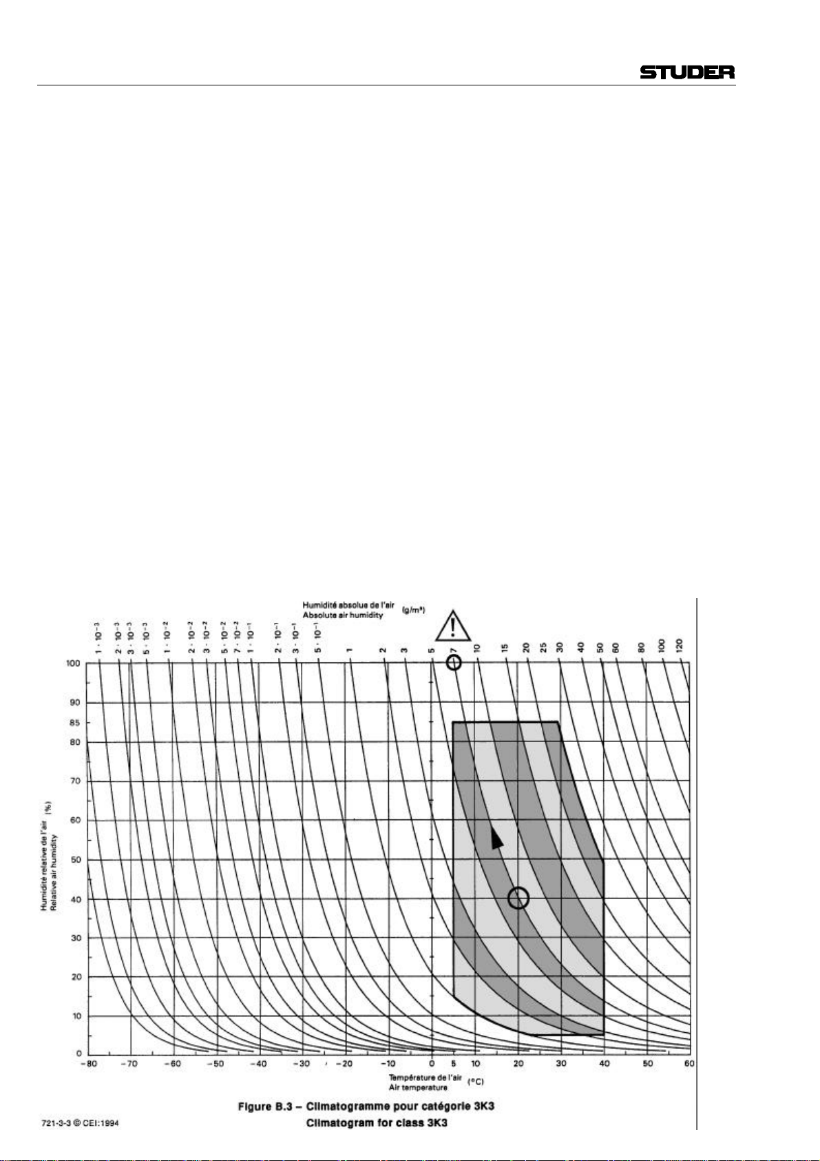
Die Zusammenhänge sind im folgenden Klimatogramm ersichtlich. Zum kontrollierten Verfahren gehören Thermometer
und Hygrometer sowie ein Thermometer innerhalb des Systems.
Beispiel 1: Ein Ü-Wagen mit einer Innentemperatur von 20 °C
und 40% relativer Luftfeuchtigkeit wird am Abend abgeschaltet. Sinkt die Temperatur unter +5 °C, bildet sich Tau oder Eis.
Beispiel 2: Ein Ü-Wagen wird morgens mit 20 °C warmer Luft
von 40% relativer Luftfeuchtigkeit aufgewärmt. Auf Teilen, die
kälter als +5 °C sind, bildet sich Tau oder Eis.
Before putting into operation, the system must be checked for
internal formation of condensation or ice. Only with a minute
formation of ice, direct evaporation (sublimation) may be expected; otherwise the system must be heated and dried while
switched off.
A system without visible internal formation of ice or condensation should be heated up with its own heat dissipation, as homogeneously (and subsequently as slow) as possible; the ambient temperature should then always be lower than the outgoing
air.
If it is absolutely necessary to operate the system immediately
within warm ambient air, this air must be dehydrated. In such a
case, the absolute humidity must be so low that the relative
humidity, related to the coldest system surface, always remains
below 100%.
Ensure that the enclosed air is as dry as possible when powering off (i.e. before switching off in winter, aerate the room with
cold, dry air, and remove humid objects as clothes from the
room).
These relationships are visible from the following climatogram.
For a controlled procedure, thermometer and hygrometer as well
as a thermometer within the system will be required.
Example 1: An OB-van having an internal temperature of
20 °C and rel. humidity of 40% is switched off in the evening.
If temperature falls below +5 °C, dew or ice will be forming.
Example 2: An OB-van is heated up in the morning with air of
20 °C and a rel. humidity of 40%. On all parts being cooler than
+5 °C, dew or ice will be forming.
VI
Page 8

WARTUNG / MAINTENANCE
Wartung und Reparatur
Durch Entfernen von Gehäuseteilen, Abschirmungen etc.
werden stromführende Teile freigelegt. Deshalb müssen
u.a. die folgenden Grundsätze beachtet werden:
Eingriffe in das Gerät dürfen nur von Fachpersonal unter
Einhaltung der geltenden Vorschriften vorgenommen werden.
Vor Entfernen von Gehäuseteilen muss das Gerät ausgeschaltet und vom Netz getrennt werden.
Bei geöffnetem, vom Netz getrenntem Gerät dürfen Teile
mit gefährlichen Ladungen (z. B. Kondensatoren, Bildröhren) erst nach kontrollierter Entladung, heiße Bauteile
(Leistungshalbleiter, Kühlkörper etc.) erst nach deren
Abkühlen berührt werden.
Bei Wartungsarbeiten am geöffneten, unter Netzspannung
stehenden Gerät dürfen blanke Schaltungsteile und metallene Halbleitergehäuse weder direkt noch mit nichtisoliertem Werkzeug berührt werden.
Zusätzliche Gefahren bestehen bei unsachgemässer Handhabung besonderer Komponenten:
• Explosionsgefahr bei Lithium zellen, Elektrolyt-Kondensatoren und Leistungshalbleitern
• Implosionsgefahr bei evakuierten Anzeigeeinheiten
• Strahlungsgefahr bei Lasereinheiten (nichtioni sierend),
Bildröhren (ionisierend)
• Verätzungsgefahr bei Anzeigeeinheiten (LCD) und
Komponenten mit flüssigem Elektrolyt.
Solche Komponenten dürfen nur von ausgebildetem
Fachpersonal mit den vorgeschriebenen Schutzmitteln
(u.a. Schutzbrille, Handschuhe) gehandhabt werden.
Maintenance and Repair
The removal of housing parts, shields, etc. exposes energized parts. For this reason the following precautions should
be observed:
Maintenance should only be performed by trained personnel in accordance with the applicable regulations.
The equipment should be switched off and disconnected
from the AC power outlet before any housing parts are
removed.
Even if the equipment is disconnected from the power,
parts with hazardous charges (e.g. capacitors, picture
tubes) must not be touched until they have been properly
discharged. Touch hot components (power semiconductors, heat sinks, etc.) only when cooled off.
If maintenance is performed on a unit that is opened and
switched on, no uninsulated circuit components and metallic semiconductor housings must be touched neither with
your bare hands nor with uninsulated tools.
Certain components pose additional hazards:
• Explosion hazard from lithium batteries, electrolytic
capacitors and power semiconductors
• Implosion hazard from evacuated display units
• Radiation hazard from laser units (non-ionizing), picture tubes (ionizing)
• Caustic effect of display units (LCD) and such comp onents containig liquid electrolyte.
Such components should only be handled by trained
personnel who are properly protected (e.g. safety
goggles, gloves).
VII
Page 9

WARTUNG / MAINTENANCE
Elektrostatische Entladung (ESD)
bei Wartung und Reparatur
ATTENTION:
ATTENTION:
ACHTUNG:
Viele ICs und andere Halbleiter sind empfindlich gegen
elektrostatische Entladung (ESD). Unfachgerechte Behandlung von Baugruppen mit solchen Komponenten bei
Wartung und Reparatur kann deren Lebensdauer drastisch
vermindern.
Bei der Handhabung der ESD-empfindlichen Komponenten sind u.a. folgende Regeln zu beachten:
• ESD-empfindliche Komponenten dürfen aus schliesslich
in dafür bestimmten und bezeichneten Verpackungen
gelagert und transportiert werden.
• Unverpackte, ESD-empfindliche Komponenten dürfen
nur in dafür eingerichteten Schutzzonen (EPA, z.B.
Gebiet für Feldservice, Reparatur- oder Serviceplatz)
gehandhabt und nur von Personen berührt werden, die
durch ein Handgelenkband mit Seriewiderstand mit dem
Massepotential des Reparatur- oder Serviceplatzes verbunden sind. Das gewartete Gerät wie auch Werkzeug,
Hilfsmittel, EPA-taugliche (elektrisch halbleitende)
Arbeits-, Ablage- und Bodenmatten müssen ebenfalls
mit diesem Potential verbunden sein.
• Die Anschlüsse der ESD-empfindlichen Komponenten
dürfen unkontrolliert weder mit elektrostatisch aufladbaren (Gefahr von Spannungsdurchschlag), noch mit
metallischen Oberflächen (Schockentladungsgefahr) in
Berührung kommen.
• Um undefinierte transiente Beanspruchung der Komponenten und deren eventuelle Beschädigung durch unerlaubte Spannung oder Ausgleichsströme zu vermeiden, dürfen elektrische Verbindungen nur am abgeschalteten Gerät und nach dem Abbau allfälliger Kondensatorladungen hergestellt oder getrennt werden.
Electrostatic Discharge (ESD)
during Maintenance and Repair
Observe precautions for handling devices sensitive to
electrostatic discharge!
Respecter les précautions d’usage concernant la manipulation de composants sensibles à l’électricité statique!
Vorsichtsmassnahmen bei Handhabung elektrostatisch
entladungsgefährdeter Bauelemente beachten!
Many ICs and semiconductors are sensitive to electrostatic
discharge (ESD). The life of components containing such
elements can be drastically reduced by improper handling
during maintenance and repair work.
Please observe the following rules when handling ESD
sensitive components:
• ESD sensitive components should only be stored and
transported in the packing material specifically provided for this purpose.
• Unpacked ESD sensitive components should only be
handled in ESD protected areas (EPA, e.g. area for
field service, repair or service bench) and only be touched by persons who wear a wristlet that is connected
to the ground potential of the repair or service bench by
a series resistor. The equipment to be repaired or serviced and all tools, aids, as well as electrically semiconducting work, storage and floor mats should also be
connected to this ground potential.
• The terminals of ESD sensitive components must not
come in uncontrolled contact with electrostatically
chargeable (voltage puncture) or metallic surfaces
(discharge shock hazard).
• To prevent undefined transient stress of the components
and possible damage due to inadmissible voltages or
compensation currents, electrical connections should
only be established or separated when the equipment is
switched off and after any capacitor charges have decayed.
VIII
Page 10
WARTUNG / MAINTENANCE
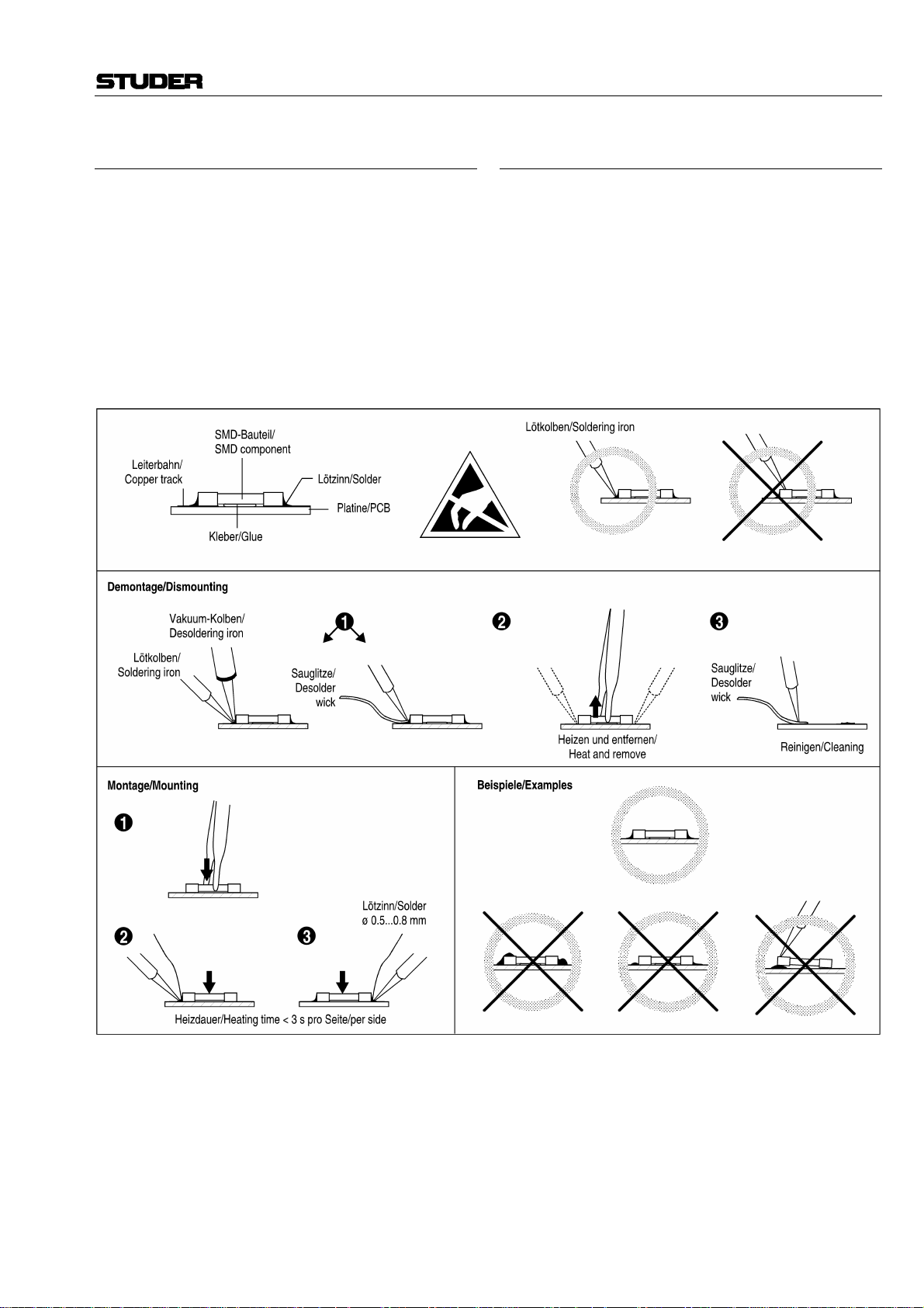
SMD-Bauelemente
Der Austausch von SMD-Bauelementen ist ausschliesslich
geübten Fachleuten vorbehalten. Für verwüstete Platinen
können keine Ersatzansprüche geltend gemacht werden.
Beispiele für korrekte und falsche SMD-Lötverbindungen
in der Abbildung weiter unten.
Bei Studer werden keine handelsüblichen SMD-Teile
bewirtschaftet. Für Reparaturen sind die notwendigen
Bauteile lokal zu beschaffen. Die Spezifikationen von
Spezialbauteilen finden Sie in der Serviceanleitung.
SMD Components
SMDs should only be replaced by skilled specialists. No
warranty claims will be accepted for circuit boards that
have been ruined. Proper and improper SMD soldering
joints are depicted below.
Studer does not keep any commercially available SMDs in
stock. For repair the corresponding devices should be
purchased locally. The specifications of special components can be found in the service manual.
IX
Page 11

EMV / EMC
Störstrahlung und Störfestigkeit
Das Gerät entspricht den Schutzanforderungen auf dem
Gebiet elektromagnetischer Phänomene, wie u.a. in den
Richtlinien 89/336/EWG und FCC, Part 15, aufgeführt:
1. Vom Gerät erzeugte elektromagnetische Strahlung ist
soweit begrenzt, dass bestimmungsgemässer Betrieb
anderer Geräte und Systeme möglich ist.
2. Das Gerät weist eine angemessene Festigkeit gegen
elektromagnetische Störungen auf, so dass sein bestimmungsgemässer Betrieb möglich ist.
Das Gerät wurde getestet und erfüllt die Bedingungen der
im Kapitel „Technische Daten“ aufgeführten EMVStandards. Die Limiten dieser Standards gewährleisten mit
angemessener Wahrscheinlichkeit sowohl den Schutz der
Umgebung wie auch entsprechende Störfestigkeit des
Gerätes. Absolute Garantie, dass keine unerlaubte elektromagnetische Beeinträchtigung während des Betriebes
entsteht, ist jedoch nicht gegeben.
Um die Wahrscheinlichkeit solcher Beeinträchtigung
weitgehend auszuschliessen, sind u.a. folgende Massnahmen zu beachten:
• Installieren Sie das Gerät gemäss den Angaben in der
Betriebsanleitung, und verwenden Sie das mitgelieferte
Zubehör.
• Verwenden Sie im System und in der Umgebung, in
denen das Gerät eingesetzt ist, nur Kom ponenten (Anlagen, Geräte), die ihrerseits die Anforderungen der
obenerwähnten Standards erfüllen.
• Sehen Sie ein Erdungskonzept des Systems vor, das
sowohl die Sicherheitsanforderungen (die Erdung der
Geräte gemäss Schutzklasse I mit einem Schutzleiter
muss gewährleistet sein), wie auch die EMV-Belange
berücksichtigt. Bei der Entscheidung zwischen sternoder flächenförmiger bzw. kombinierter Erdung sind
Vor- und Nachteile gegeneinander abzuwägen.
• Benutzen Sie abgeschirmte Kabel, wo vorgesehen.
Achten Sie auf einwandfreie, grossflächige, korrosionsbeständige Verbindung der Abschirmung zum entsprechenden Steckeranschluss und dessen Gehäuse. Beachten Sie, dass eine nur an einem Ende angeschlossene
Kabelabschirmung als Sende- bzw. Empfangsantenne
wirken kann (z.B. bei wirksamer Kabellänge von 5 m
oberhalb von 10 MHz), und dass die Flanken digitaler
Kommunikationssignale hochfrequente Aussendungen
verursachen (z.B. LS- oder HC-Logik bis 30 MHz).
• Vermeiden Sie Bildung von Masseschleifen oder vermindern Sie deren unerwünschte Auswirkung, indem
Sie deren Fläche möglichst klein halten und den darin
fliessenden Strom durch Einfügen einer Impedanz (z.B.
Gleichtaktdrossel) reduzieren.
Electromagnetic Compatibility
The equipment conforms to the protection requirements
relevant to electromagnetic phenomena that are listed in
the guidelines 89/336/EC and FCC, part 15.
1. The electromagnetic interference generated by the
equipment is limited in such a way that other equipment
and systems can be operated normally.
2. The equipment is adequately protected against electromagnetic interference so that it can operate correctly.
The unit has been tested and conforms to the EMC standards applicable to residential, commercial and light industry, as listed in the section „Technical Data“. The limits
of these standards reasonably ensure protection of the
environment and corresponding noise immunity of the
equipment. However, it is not absolutely warranted that
the equipment will not be adversely affected by electromagnetic interference during operation.
To minimize the probability of electromagnetic interference as far as possible, the following recommendations
should be followed:
• Install the equipment in accordance with the operating
instructions. Use the supplied accessories.
• In the system and in the vicinity where the equipment is
installed, use only components (systems, equipment)
that also fulfill the above EMC standards.
• Use a system grounding concept that satisfies the safety
requirements (protection class I equipment must be
connected with a protective ground conductor) that also
takes into consideration the EMC requirements. When
deciding between radial, surface or combined grounding, the advantages and disadvantages should be carefully evaluated in each case.
• Use shielded cables where shielding is specified. The
connection of the shield to the corresponding connector
terminal or housing should have a large surface and be
corrosion-proof. Please note that a cable shield connected only single-ended can act as a transmitting or receiving antenna (e.g. with an effective cable length of
5 m, the frequency is above 10 MHz) and that the edges
of the digital communication signals cause highfrequency radiation (e.g. LS or HC logic up to
30 MHz).
• Avoid ground loops or reduce their adverse effects by
keeping the loop surface as small as possible, and reduce the noise current flowing through the loop by inserting an additional impedance (e.g. common-mode rejection choke).
X
Page 12

Class A Equipment - FCC Notice
Konformitätserklärungen / Declarations of conformity
This equipment has been tested and found to comply with
the limits for a Class A digital device, pursuant to Part 15
of the FCC Rules. These limits are designed to provide a
reasonable protection against harmful interference when the
equipment is operated in a commercial environment. This
equipment generates, uses, and can radiate radio frequency
energy and, if not installed and used in accordance with the
instruction manual, may cause harmful interference to radio
communications. Operation of this equipment in a residen-
CE-Konformitätserklärung
Der Hersteller,
Studer Professional Audio AG,
CH-8105 Regensdorf,
erklärt in eigener Verantwortung, dass die Produkte
Studer D19 MicAD, 8-Channel Mic/Line Preamplifier
with Digital Outputs (ab Serie-Nr. 101),
Studer D19 MicAD Stage, Remote Controlled 8-Channel
Mic/Line Preamplifier with Digital Outputs (ab SerieNr. 1001),
Studer D19 MicAD Master, Remote Control (ab Serie-
Nr. 1001),
auf die sich diese Erklärung bezieht, entsprechend den
Bestimmungen der EU-Richtlinien und Ergänzungen
• Elektromagnetische Verträglichkeit (EMV):
89/336/EWG + 92/31/EWG + 93/68/EWG
• Niederspannung:
73/23/EWG + 93/68/EWG
mit den folgenden Normen und normativen Dokumenten
übereinstimmen:
• Sicherheit:
Schutzklasse 1, EN 60950:1992 + A1/A2:1993
• EMV:
EN 50081-1:1992, EN 50082:1992.
Regensdorf, 6. Februar 1996
tial area is likely to cause harmful interference in which
case the user will be required to correct the interference at
his own expense.
Caution:
Any changes or modifications not expressly approved by
the manufacturer could void the user's authority to operate
the equipment. Also refer to relevant information in this
manual.
CE Declaration of Conformity
The manufacturer,
Studer Professional Audio AG,
CH-8105 Regensdorf,
declares under his sole responsibility that the products
Studer D19 MicAD, 8-Channel Mic/Line Preamplifier
with Digital Outputs (from serial no. 101),
Studer D19 MicAD Stage, Remote Controlled 8-Channel
Mic/Line Preamplifier with Digital Outputs (from serial no. 1001),
Studer D19 MicAD Master, Remote Control (from serial
no. 1001),
to which this declaration relates, according to following
regulations of EU directives and amendments
• Electromagnetic Compatibility (EMC):
89/336/EEC + 92/31/EEC + 93/68/EEC
• Low Voltage (LVD):
73/23/EEC + 93/68/EEC
are in conformity with the following standards or other
normative documents:
• Safety:
Class 1, EN 60950:1992 + A1/A2:1993
• EMC:
EN 50081-1:1992, EN 50082:1992.
Regensdorf, February 6, 1996
B. Hochstrasser, Geschäftsleiter
P. Fiala, Leiter QS
B. Hochstrasser, Managing director
P. Fiala, Manager QA
XI
Page 13

Studer D19 MicAD
Corrigendum
Section “Technical specifications”
Please note the following correction in the technical specifications:
Crosstalk:
Line-Line/Mic-Mic
< –96 dB @ 1 kHz; < –92 dB @ 20 Hz...20 kHz
Kapitel “Technische Daten”
Bitte beachten Sie die folgende Korrektur der
technischen Daten:
Übersprechen:
Line-Line/Mic-Mic
< –96 dB bei 1 kHz; < –92 dB, 20 Hz...20 kHz
Page 14

NEUE FUNKTION FÜR MICAD MASTER
Zum Begrenzen der Anzahl der Fernsteuerkanäle (d.h. der Anzahl der
durch den MicAD MASTER gesteuerten Geräte) wurde eine neue Funktion implementiert. Bisher mussten zur Wahl des gewünschten Gerätes
immer alle 16 Adressen «durchgeblättert» werden, auch wenn nur zwei
oder drei Geräte am MicAD MASTER angeschlossen waren.
Zum Begrenzen der Anzahl der Fernsteuerkanäle gehen Sie wie folgt
vor:
• CTRL CH-Taste so oft wie nötig drücken, damit im Display die gewünschte Anzahl ferngesteuerter Einheiten angezeigt wird.
• MODE-Taste drücken und festhalten, anschliessend SYNC-Taste drükken und festhalten, dann CTRL CH-Taste drücken.
Danach wird beim Blättern mit der Taste CTRL CH nur bis zur gewählten Fernsteuerkanal-Nummer gezählt und anschliessend wieder bei 1
begonnen.
Ausschalten der Funktion:
• MODE-Taste drücken und festhalten, anschliessend SYNC-Taste drükken und festhalten, dann REMOTE-Taste drücken.
Nun können wieder alle Fernsteuerkanäle mit der CTRL CH-Taste gewählt werden.
D19 MicAD
NEW FUNCTION FOR MICAD MASTER
For limiting the number of remote control channels (i.e. the number of
units controlled by the MicAD MASTER), a new function has been
created. Up to now, all 16 addresses had to be toggled through when
selecting a particular unit for control, even if only two or three units
were connected to the MicAD MASTER.
To limit the number of remote control channels, proceed as follows:
• Press the CTRL CH key as many times as required until the display
indicates the desired number of units.
• Press and hold the MODE key, then press and hold the SYNC key, then
press the CTRL CH key.
After that, the display will count up only to the number entered before
when toggling with the CTRL CH key, and then restarts with 1.
To cancel this function:
• Press and hold the MODE key, then press and hold the SYNC key, then
press the REMOTE key.
After that, all remote control channels can be accessed again when
toggling with the CTRL CH key.
Edition:
17.02.98
Addendum
Page 15

19.02.01
CONTENTS
D19 MicAD
1 Come in! ........................................................................E1/1
1.1 Basic information ......................................................... E1/1
1.2 General ....................................................................... E1/2
1.2.1 Scope of delivery ..................................................... E1/2
1.2.2 D19 MicAD versions................................................ E1/2
1.2.3 Options ...................................................................E1/2
1.2.4 Accessories ..............................................................E1/3
1.3 Safety and connections ................................................ E1/4
1.3.1 Utilization for the purpose intended .........................E1/4
1.3.2 Power connection ....................................................E1/4
1.3.3 Connector panel ...................................................... E1/5
1.4 Technical specifications ............................................... E1/6
1.4.1 Audio specifications ................................................. E1/6
1.4.2 Peripheral connections ............................................. E1/7
1.4.3 Power supply ........................................................... E1/7
1.4.4 Primary fuse ............................................................. E1/7
1.4.5 Operating conditions ............................................... E1/7
1.4.6 Safety and EMC standards ........................................ E1/7
1.4.7 Mechanical data MicAD/MicAD STAGE................... E1/8
1.4.8 Mechanical data MicAD MASTER ............................ E1/8
2 Operation ......................................................................E2/1
2.1 Operating elements ...................................................... E2/1
2.2 Audio and sync connections, pin assignments ............. E2/5
2.2.1 Mic and line inputs ..................................................E2/5
2.2.2 Digital outputs ......................................................... E2/5
2.2.3 External AES/EBU synchronization ........................... E2/5
2.2.4 Word clock in/out .................................................... E2/5
2.2.5 Using the TDIF-1 8-channel interface ....................... E2/6
2.2.6 Using the optical ADAT 8-channel interface............. E2/7
2.3 Application ideas and examples .................................. E2/8
2.3.1 Wiring for external synchronization ....................... E2/10
2.4 Remote control .......................................................... E2/11
2.4.1 General, hardware .................................................E2/11
2.4.2 RS422 .................................................................... E2/11
2.4.3 MIDI ...................................................................... E2/13
2.4.4 Programming ......................................................... E2/15
2.4.4.1 Recognized MIDI messages ..................... E2/15
2.4.4.2 Control change ....................................... E2/15
2.4.4.3 System exclusive ..................................... E2/16
2.4.4.4 Transmitted MIDI messages ..................... E2/17
2.4.4.5 MicAD internal system status field........... E2/17
Edi tion:
Contents E 0/1
Page 16

19.02.01
D19 MicAD
3 Additional information ...................................................E3/1
3.1 What the heck is Noise Shaping? ................................. E3/1
3.2 Block diagrams ............................................................ E3/3
3.2.1 Global audio block diagram ..................................... E3/3
3.2.2 Synchronization block diagram ................................E3/3
4 Appendix: MIDI protocol ................................. yellow pages
E 0/2 Contents
“ADAT” is a trade mark of Alesis Corporation.
“TDIF-1” is a trade mark of Tascam Corporation.
Edi tion:
Page 17

19.02.01
1 COME IN!
1.1 Basic information
D19 MicAD
We are happy to welcome you in the steadily growing circle of the
Studer D19 MicAD's users, and we felicitate you on your selection.
Thanks to Studer's experience collected during more than 40 years of
business in the professional audio products field, you may expect that
the performance of your new unit will fulfill your highest demands.
The MicAD is a simple, reliable, selfcontained eight-channel microphone preamplifier with digital outputs.
MicAD combines the renowned low-distortion Studer transformer-balanced microphone inputs with high-performance 20 bit A/D converters.
For optimum sound quality even in 16 bit mode, DSP dithering and noise
shaping are used instead of simple truncating.
MicAD features AES/EBU outputs plus a choice of TDIF-1 or optical
ADAT format outputs.
Remote control is possible via the dedicated MicAD Master or via external equipment using MIDI-RS 422 or MIDI.
Edi tion:
Come in! E 1/1
Page 18

19.02.01
D19 MicAD
1.2 General
1.2.1 Scope of delivery
The D19 MicAD is supplied with a power cord (or an IEC 320/C13
socket), a 2.5 mm hex-socket screwdriver, and this operating manual.
1.2.2 D19 MicAD versions Order No.
D19 MicAD Self-contained 8-channel Mic/Line preamplifier 66.650.00000
with digital outputs
• 8 high-quality Mic/Line preamps with separate
XLR inputs.
• 4 AES/EBU outputs on XLR.
• 20-bit high-performance A/D converters.
• Switchable DSP Dithering and Noise Shaping.
• Local or remote control of individual GAIN,
MIC/LINE, Phase, 48 V Phantom Power and
High-pass filter settings.
• Local or remote control of global Soft-clip,
Mode, Sync, and Sampling Frequency settings.
• Built-in 100...240 V power supply.
D19 MicAD STAGE Remote controlled 8-channel Mic/Line preampli- 66.651.00000
fier with digital outputs
as D19 MicAD (above), except:
• Remote control for all functions of the unit.
• Front panel controls: Only Power switch,
CTRL CH and REMOTE keys.
D19 MicAD MASTER Dedicated remote controller for up to 16 MicAD 66.653.00000
units.
1.2.3 Options Order No.
Digital Audio Output Options:
ADAT Interface: 8-channel optical digital audio output card 1.650.050.20
for connecting with the ADAT and compatible
8-channel recorders or other equipment featuring
the ADAT standard connectors.
TDIF-1 Interface: 8-channel digital audio output card 1.650.052.20
for connecting with the DA-88 and compatible
8-channel recorders or other equipment featuring
the TDIF-1 standard connectors.
E 1/2 Come in!
Edi tion:
Page 19

D19 MicAD
19.02.01
Control Port Options:
MIDI Merge Module: For connection with MIDI compatible controllers 1.650.060.20
featuring MIDI In, Out, Thru, Return connectors
for simple remote control daisy-chaining of up to
16 MicAD units.
MIDI RS422 Module: For connection with the MicAD MASTER or other 1.650.065.20
RS422 compatible controllers
featuring In/Out and Thru/Return connectors for
simple remote control daisy-chaining of up to
16 MicAD units.
1.2.4 Accessories Order No.
Accessories/Spares: Kit, consisting of: 20.020.302.48
• Mating XLR connectors (10 pcs. male,
4 pcs. female)
• Mic/Line Gain knobs (2 pcs. each)
• Rack mounting screws with washers
(4 pcs. each)
• Identification strip (1 pc.)
• 9-pin D-Type connectors (2 pcs.)
Interface cables: ADAT/Alesis optical interface cable, 10.325.010.00
length 1.0 m
ADAT/Alesis optical interface cable, 10.325.011.00
length 5.0 m
TDIF-1/Tascam interface cable F-10.025.031.08
“PW 88D”, length 1.0 m
TDIF-1/Tascam interface cable F-10.025.031.09
“PW 88D”, length 5.0 m
RS422 Remote control cable, length 15.0 m 1.023.745.81
For interconnection between D19 MicAD
MASTER and D19 MicAD STAGE or D19 MicAD
units or other compatible RS422 controllers.
RS422 Remote control cable, length 1.0 m 1.023.754.00
For interconnection between several D19 MicAD
STAGE or D19 MicAD units (or D19 MicAD
MASTER, if required).
Edi tion:
Come in! E 1/3
Page 20

19.02.01
D19 MicAD
1.3 Safety and connections
1.3.1 Utilization for the purpose intended
The Studer D19 MicAD 8-channel Mic/Line preamplifier is designed for
professional use. It is presumed that the unit is operated only by trained
personnel; servicing must be performed by qualified experts.
The electrical connections may be connected only to the appropriate
voltages and signals specified in this manual. Please consult the “Safety
and EMC” section at the very beginning of this manual.
1.3.2 Power connection
There is no need to select a specific mains voltage setting because the
Studer D19 MicAD can be operated on mains voltages from 100 through
240 VAC.
Caution! Repair work may only be performed by a trained service technician. The
primary fuse of the D19 MicAD must be replaced by a spare fuse of
exactly the same type. The D19 MicAD must not be opened by the user
because of the risk of a severe electric shock hazard!
Power cable The supplied power socket has to be fitted with a mating power cable
incl. plug by an electrician, if your local Studer agency or your dealer
should not have added a fitting power cable.
☛ Please consult the “Safety” section at the very beginning of this
manual.
E 1/4 Come in!
Edi tion:
Page 21

19.02.01
1.3.3 Connector panel
D19 MicAD
MIDI REMOTE
1
3
4
5
2
RETURNIN OUTTHRU
RS422 REMOTE CONTROL
[2]
LINE INPUTS
MIC INPUTS SYNCHRONIZATION
8 AES 3/4AES 1/2 AES 7/8
7
36
45
1245 3678
2
1
IN/OUT RETURN/THRU
DIGITAL OUT
WCLK OUTWCLK INAES IN
[7] [8] [7] [1][3]
DIGITAL MCH OUT
DIGITAL MCH OUT
[9]
[1] AC POWER Connector for socket IEC 320/C13.
Supply voltage range 100...240 V
(without voltage selector); mains fre-
AC
quency 50...60 Hz.
For connecting to the mains, please consult the Safety section at the
very beginning of this manual.
OPTICAL OUT
[5][6]
TDIF-1
AES 5/6
[2] LINE INPUTS Analog Line inputs on female XLR connectors. Sensitivity for full-scale
input level of the A/D converter adjustable from –5 dBu to +24 dBu.
Input impedance 11 kΩ, transformer-balanced.
[3] MIC INPUTS Microphone inputs on female XLR connectors. Sensitivity for full-scale
input level of the A/D converter adjustable from –49 dBu to +20 dBu.
Input impedance 1 kΩ, transformer-balanced.
[4] DIGITAL OUT AES/EBU Outputs on male XLR connectors, transformer-balanced. Out-
put impedance 110 Ω.
[5] Optional Digital Outputs TDIF-1 eight-channel format or optical ADAT eight-channel format.
[6] Remote Control Options For installation of optional remote modules: Either MIDI-RS422 module
or MIDI merge module .
[7] AES IN Input for external synchronization via AES/EBU (female XLR connector).
[8] WCLK IN Input for external Word Clock synchronization (BNC connector).
[9] WCLK OUT Output of the Word Clock Sync signal (BNC connector).
Edi tion:
Come in! E 1/5
Page 22

19.02.01
D19 MicAD
1.4 Technical specifications (subject to change without notice)
1.4.1 Audio specifications (all measurements at f
Frequency response: Microphone 20 Hz...20 kHz, ±0.4 dB
Line 20 Hz...20 kHz, ±0.1 dB
A/D converter: Delta-Sigma, 64 × oversampling, resolution 20 bit, linear.
Mic input noise figure: typ. < 3.5 @ max. gain, 20 Hz...20 kHz, 24°C
Signal/noise ratio: A/D converter > 106 dBFS, CCIR 468-3
THD + Noise: Line < –85 dBFS @ 20 Hz...24 kHz, Full Scale
Crosstalk: Line-Line/Mic-Mic
< –96 dB @ 1 kHz; < –92 dB @ 20 Hz...20 kHz
Analog inputs: 8 separate Mic and Line inputs on XLRs, transformer-balanced and float-
ing.
8 dual concentric potentiometers for MIC/LINE Gain control.
Functions selectable per channel: Phase, Phantom (Mic input only),
High-pass filter (–3 dB @ 75 Hz, 12 dB/oct.; Mic input only).
Stereo Link Control for adjacent channel pairs.
Selectable for all channels simultaneously: Soft Clip.
Input sensitivity range for Full Scale:
Mic –49...+20 dBu
Line –5...+24 dBu
= 48 kHz)
S
Maximum input level (analogue): Mic +20 dBu
Line +24 dBu
Interchannel gain deviation (stereo pairs):
Mic < 0.5 dB
Line < 0.05 dB
Input impedance: Microphone 1 kΩ
Line 11 kΩ
Metering: PPM, peak program meter with switchable Peak Hold function;
16-segment bargraph displays, range –60 dBFS...Overload.
Digital audio processing: DC reject (always on)
Output word length 20 bit, 16 bit with Dithering or 16 bit with Noise
Shaping.
Digital outputs: 4 AES/EBU outputs on XLRs, transformer-balanced and floating accord-
ing to AES3-1992, ANSI S4.40-1992
Amplitude 2...5 V
Impedance 110 Ω
Optional outputs: • TDIF-1 8-channel, 20 or 16 bit serial audio data with sampling fre-
quency information; C-MOS level.
• ADAT optical 8-channel format.
E 1/6 Come in!
Edi tion:
Page 23

19.02.01
1.4.2 Peripheral connections
Synchronization/sampling rate: Word Clock IN 30...54 kHz, TTL level, impedance 75 Ω
Word Clock OUT 30...54 kHz, TTL level, impedance 75 Ω
AES/EBU IN 30...54 kHz, transformer-balanced and floating,
impedance 110 Ω, according to AES 11-1991
Internal clock 44.1 kHz / 48 kHz
Remote control: Control ports: MIDI or MIDI-RS422 (optional)
Device number: 1...16 or OMNI mode, settable on front panel
Remote: ON/OFF, selectable on front panel
1.4.3 Power supply
Mains voltage: 100...240 VAC, 50...60 Hz
Current consumption: 0.5...0.25 A
D19 MicAD
Appliance inlet: IEC 320/C14
Primary fuse: T 2.0 A H 250 V UL, CSA
1.4.4 Primary fuse
Caution: The primary fuse is located inside the D19 MicAD/MicAD STAGE. Re-
pair work may only be performed by a trained service technician. The
primary fuse of unit must be replaced by a spare fuse of exactly the same
type. The unit must not be opened by the user – risk of a severe electric
shock hazard!
Spare fuse: T 2.0 A H 250 V UL, CSA (5 × 20 mm) Order No. 51.01.1022
1.4.5 Operating conditions
Ambient air temperature: +10°...+40°C
Relative humidity: Category F (DIN 40040)
1.4.6 Safety and EMC standards
Safety: Protection class I according to EN 60950; 1992 + A1/A2; 1993 (UL
1950)
EMC: Product family standard for audio, video, audio-visual, and entertain-
ment lighting control apparatus for professional use.
Emission: EN 50081-1; 1992
Immunity: EN 50082-1; 1992
Edi tion:
Come in! E 1/7
Page 24

19.02.01
D19 MicAD
(Knobs)
(Rubber feet)
1.4.7 Mechanical data MicAD/MicAD STAGE
Weight: approx. 6 kg, all options installed.
Dimensions: [mm]
88.3
482.4
1.4.8 Mechanical data MicAD MASTER
MicAD MASTER can be installed into the meter panel section of Studer
mixing consoles.
Weight: approx. 2.5 kg.
Dimensions: [mm]
482.4
approx. 19
(BNC)
365
approx. 19
(Knobs; MicAD only)
130
approx. 19
88.3
approx. 8
(Rubber feet)
approx. 8
E 1/8 Come in!
Remote
Edi tion:
Page 25

19.02.01
2 OPERATION
2.1 Operating elements
[4]
D19 MicAD
[3]
[5]
MicAD
POWER
OVL
–1
–3
–6
–9
–12
–18
–24
–30
–40
–60
12
MIC
18
LINE
24 -6
dBu/FS
LINE
OVL
–1
–3
–6
MIC
–9
–12
LINE
Ø
–18
48V
–24
–30
–40
–60
6
12
0
18
24 -6
dBu/FS
1
LINE
MIC
LINE
Ø
48V
LINK
SEL SEL SEL SEL SEL SEL SELSEL
6
0
18
2 3
OVL
–1
–3
–6
–9
–12
–18
–24
–30
–40
–60
12
24 -6
dBu/FS
OVL
–1
–3
–6
MIC
–9
–12
LINE
Ø
–18
48V
–24
–30
–40
–60
6
0
LINE
6
12
18
24 -6
dBu/FS
LINE
OVL
–1
–3
–6
MIC
–9
–12
LINE
Ø
–18
48V
–24
–30
LINK
–40
–60
12
18
0
24
dBu/FS
4 5
LINE
OVL
–1
–3
–6
MIC
–9
–12
LINE
Ø
–18
48V
–24
–30
–40
–60
6
12
0
18
-6
24
dBu/FS
LINE
MIC
LINE
Ø
48V
LINK
6
0
18
-6
6 7
OVL
–1
–3
–6
–9
–12
–18
–24
–30
–40
–60
12
24
dBu/FS
LINE
OVL
–1
–3
–6
MIC
LINE
Ø
48V
6
0
-6
MIC
–9
–12
LINE
Ø
–18
48V
–24
–30
LINK
–40
–60
6
12
18
0
24
-6
dBu/FS
LINE
[1] [8] [2] [6]
MIC/LINE
Ø
48V
STEREO LINK
PEAK HOLD SOFT CLIP REMOTE
8
[9] [10] [13]
[7]
[11] [12] [14]
D19 SERIES
SOFT
HOLD
INT
WCLK
16DI
AES
16NS
AUTO
20BIT
MODE SYNC CTRL CH
REM
48
44
VAR
MicAD
[1] POWER Switches the unit on or off. The unit is ready to operate with the factory
default settings. The subsequent settings remain stored in a Flash
EPROM after switching the unit off (unit contains no battery).
CHANNEL FUNCTIONS: The following functions operate on individual channels:
[2] SEL Toggle key to select or deselect one or more of the eight channels to
be operated on (Functions [3]...[7]). Multiple channel selection is possible by holding one of the SEL keys down and pressing several SEL
keys successively.
[3] MIC/LINE Toggle key to select the MIC INPUT or LINE INPUT of the selected
channel(s).
[4] Ø Toggle key to activate the phase reverse switch of the selected chan-
nel(s).
[5] 48 V Toggle key to activate the 48 V phantom power supply for the selected
microphone channel(s).
[6] Activates the high pass filter on the microphone inputs of the selected
channel(s). Cut-off frequency (–3 dB point) 75 Hz, slope 12 dB/octave.
[7] STEREO LINK Activates the STEREO LINK of the selected channel(s) in pairs (1/2, 3/
4, 5/6, 7/8). The linked channels are then controlled as a stereo pair
from the odd channel’s controls. If linked, the odd-numbered channel's gain potentiometer sets the gain of both the odd- and even-numbered channels. Mic/Line setting, Gain setting, 48 V phantom power
supply and high-pass filter setting of the odd channels are copied into
the evennumbered channels. Exception: The phase reversal function
can always be controlled individually. After having deselected the
link function, the even-numbered channel retains the settings which
have been copied from the odd-numbered channel, but all channel
functions can be controlled individually again.
Edi tion:
Operation E 2/1
Page 26

19.02.01
D19 MicAD
[8] LINE/MIC Potentiometer Adjusts the gain of the LINE INPUT (ring) and the MIC INPUT (knob) in
1 dB steps. The printed scale on the front panel corresponds to the
LINE INPUT.
LINE INPUT, Headroom The LINE potentiometer is calibrated in dBu per full-scale. It repre-
sents the dBu value of an analog input signal which causes a fullscale output of the A/D converter.
Example: A studio works with +6 dBu nominal analog level and uses 12 dB
headroom. The LINE potentiometer should then be set to 18 dBu.
Full scale
6 dBu + 12 dB =
Potentiometer
setting:
18 dBu
12 dB Headroom
Input signal
+6 dBu nom. level
(Panel) Setting [dBu] = Nominal level [dBu] + Headroom [dB].
E 2/2 Operation
Edi tion:
Page 27

D19 MicAD
19.02.01
GLOBAL FUNCTIONS: The following functions are activated for the entire unit:
[9] MODE Toggle key to select the word length of the DIGITAL OUTput. 20 Bit,
16 Bit with Noise Shaping or 16 Bit with dithering can be selected.
[10] SYNC Selects the synchronization source for the unit. Possible selections are:
INT 48 Internal quartz reference, 48 kHz
INT 44 Internal quartz reference, 44.1 kHz
WCLK Selects external Word Clock Sync
AES Selects external AES/EBU Sync
AUTO Selects sources automatically in the sequence AES-WCLK-INT
VAR Indication only, active if the external source frequency deviates from
48 or 44.1 kHz for more than approx. ±1%.
48
INT
44
WCLK
16DI
16NS
20BIT
[11] PEAK HOLD Toggle key to select the PEAK HOLD function for the PPM level me-
ters – either permanent or with automatic reset after approx. 2 s.
AES
AUTO
VAR
[12] SOFT CLIP Toggle key to activate the SOFT CLIP function in the analog paths to
reduce the danger of overloading the A/D converter with short signal
peaks. Threshold at 3 dB below full-scale, allowing for approx. 6 dB
reserve before hard clipping occurs.
[13] CTRL CH Toggle key to select a remote control channel (1...16), or Omni mode
(for MIDI control).
[14] REMOTE Toggle key to activate REMOTE MODE. Local controls and display
are disabled.To switch the REMOTE function off, press the key for more
than one second.
MicAD STAGE
The MicAD Stage version contains only the CTRL CH and REMOTE
keys and the POWER switch.
[13] CTRL CH Toggle key to select a remote control channel (1...16), or Omni mode
(for MIDI control).
[14] REMOTE Toggle key to activate REMOTE MODE. To switch the REMOTE func-
tion off, press the key for more than one second.
Edi tion:
Operation E 2/3
Page 28

19.02.01
D19 MicAD
MicAD MASTER
The MicAD MASTER can be used to control all functions of any MicAD
version. Usually, it is powered from the controlled MicAD; it has no
POWER switch. All functions work in the same way as on the MicAD
except for the following additional functions:
[8] LINE/MIC Potentiometer When a remote control channel is selected, the potentiometer settings
of the Master will usually be different from the ones of the selected
MicAD. Normally, audio levels are displayed. As soon as a potentiometer is slightly turned, the Master's display changes to indicate the
difference between the potentiometer setting and the actual gain setting on the MicAD.
OVL
–1
–3
–6
–9
–12
–18
–24
–30
–40
–60
MIC
LINE
Ø
48V
LINK
SEL
With reference to this indication, the corresponding potentiometer has
to be turned (down for our example) until only the center LED is on.
During this matching process the potentiometer does not change the
gain. As soon as only the center LED is on, the display changes to
indicate the signal level again, and the potentiometer position is
matched to the gain setting. From now on, the potentiometer is active
and controls the gain of the MicAD's corresponding input channel.
[13] CTRL CH Key to select the remote control channel to be operated.
D19 MicAD MASTER
Potentiometer
..
No. 2
Remote Control Channel
No. 3
Audio Channel
No. 18
In the example above, 3 MicAD units are remotely controlled by a
MicAD Master. The audio channels are numbered in succession: Unit
no. 1 holds the audio channels no. 1...8, unit no. 2 holds the audio
channels no. 9...16, and so on.
If the gain of audio channel 18 has to be adjusted, select remote control channel no. 3 by pressing CTRL CH as many times as required
until a “3” is displayed. Then, the potentiometer no. 2 adjusts the gain
of audio channel no. 18.
D19 MicAD No. 1
Audio Ch. 1...8
D19 MicAD No. 2
Audio Ch. 9...16
D19 MicAD No. 3
Audio Ch. 17...24
E 2/4 Operation
Edi tion:
Page 29

19.02.01
2.2 Audio and sync connections, pin assignments
2.2.1 Mic and line inputs
Pin assignment (XLR, 3-pin, female):
Pin Description
1
2
1
3
Ground
2
Input +
3
Input -
-
Chassis
2.2.2 Digital outputs
Pin assignment (XLR, 3-pin, male):
Pin Description
1
1 2
3
Ground
2
Output +
3
Output -
-
Chassis
D19 MicAD
2.2.3 External AES/EBU synchronization
Pin assignment (XLR, 3-pin, female):
Pin Description
1
12
3
Ground
2
Input +
3
Input -
-
Chassis
2.2.4 Word clock in/out
Input Pin assignment (BNC, 75 Ω):
Pin Description
Center
Output Pin assignment (BNC, 75 Ω):
Center
center
outer
Word Clock Input (TTL level)
Ground
Pin Description
center
outer
Word Clock Output (TTL level)
Ground
Edi tion:
Operation E 2/5
Page 30

19.02.01
D19 MicAD
2.2.5 Using the TDIF-1 8-channel interface
The Tascam TDIF-1 digital I/O format interface is used for sending digital audio data from the D19 MicAD to Tascam DA-88 and compatible
units.
Basic characteristics: 8-channel audio data with sampling frequency information, emphasis
information, and sync signal.
Signal transmission level is C-MOS, unbalanced.
Note: The maximum cable length should not exceed 10 m.
Pin assignment:
1425
DIGITAL MCH OUT
Recorder
e.g. DA-88
TDIF-1
or compatible
Cables: Order No.: F-10.025.031.08 (1.0 m)
F-10.025.031.09 (5.0 m)
Only the specified connecting cables should be used (order numbers
above).
Pin Designation
113
1
2
3
4
5
6
7
8
9
10
11
12
13
14
15
16
17
18
19
20
21
22
23
24
25
*) DA-88 ignores
**) IF-88 SD ignores
***) DA-88 ignores except “DIGITAL IN” and “FORMAT” modes
****) DA-88 displays only warning except “DIGITAL IN” and “FORMAT” modes
DOUT 1/2
DOUT 3/4
DOUT 5/6
DOUT 7/8
LRCK OUT
FS 0 OUT
GND
(FS 1 IN) **) ****)
(LRCK IN) *)
(DIN 7/8)
(DIN 5/6)
(DIN 3/4)
(DIN 1/2)
GND
GND
GND
GND
EMPHASIS OUT
FS 1 OUT
(FS 0 IN) **) ****)
(EMPHASIS IN) ***)
GND
GND
GND
GND
E 2/6 Operation
Edi tion:
Page 31

D19 MicAD
19.02.01
Cable configuration:
25-pin D-Type,
male
1
14
2
15
3
16
4
17
5
9
7
18
6
19
8
20
21
Shield + housing
10
22
11
23
12
24
13
25
Cable colours (twisted pairs)
org/red 1
org/blk 1
gry/red 1
gry/blk 1
wht/red 1
wht/blk 1
yel/red 1
yel/blk 1
pnk/red 1
pnk/blk 1
org/red 2
org/blk 2
gry/red 2
gry/blk 2
wht/red 2
wht/blk 2
yel/red 2
yel/blk 2
pnk/red 2
pnk/blk 2
org/red 3
org/blk 3
gry/red 3
gry/blk 3
wht/red 3
wht/blk 3
25-pin D-Type,
male
13
25
12
24
11
23
10
22
9
5
7
21
8
20
6
19
18
Shield + housing
4
17
3
16
2
15
1
14
2.2.6 Using the optical ADAT 8-channel interface
The ADAT format is a serial 8-channel format. It uses a single line
cable with fibre optic.
DIGITAL MCH OUT
OPTICAL OUT
Plug type: TOCP 155 k
Optical fibre: TOFC 100
The maximum cable length specified by Alesis is 1 m. However, in
most cases, operation with a cable length up to 10...15 m is possible.
Recorder
e.g. ADAT
or compatible
Edi tion:
Operation E 2/7
Page 32

19.02.01
D19 MicAD
2.3 Application ideas and examples
The D19 MicAD is perfectly suitable for a whole range of applications. Here are some suggestions:
Studio-in-a-box front end
for STUDER Dyaxis or
other DAWs.
DAW (DYAXIS)
Mic/Line front end, re-
motely controlled from a
digital mixing console or a
router
Studer
Mixing
Console
DYAXIS
DYAXIS
DYAXIS
Digital Audio Links
AES / EBU (8 lines)
or
OPTICAL 8-CH (2 lines)
2 or 8
AES / EBU
MicAD
POWER
1.023.717.00
MicAD
POWER
POWER
MIDI Control
MIC
LINE
D19 SERIES
REM
48
INT
44
WCLK
VAR
AES
AUTO
CTRL CH
REMOTE
D19 MicAD STAGE
MICRS422 Control
LINE LINE
D19 SERIES
REM
48
INT
44
WCLK
VAR
AES
AUTO
CTRL CH
REMOTE
D19 SERIESMicAD
REM
48
INT
44
WCLK
VAR
AES
AUTO
CTRL CH
REMOTE
D19 MicAD STAGE
E 2/8 Operation
Portable studio with an
8-CH Recorder (ADAT,
DA88, or compatibles), for
direct cuts from the mics
to the digital tracks.
8CH OPTICAL
(ADAT),
10.325.011.00
or
8CH TDIF-1,
F-10.025.031.09
MIC
LINE
,
D19 MicAD and 8 TRACK RECORDER
Edi tion:
Page 33

19.02.01
Optical 8-CH
Stacked Mic/Line studio
interface system, control-
led via the dedicated
remote controller MicAD
MASTER
Universal studio tool,
controlled via
a MIDI controller
MicAD
POWER
MicAD
POWER
MicAD
POWER
up to 16 MicAD STAGE
D19 MicAD
D19 SERIES
REM
48
INT
44
WCLK
VAR
AES
AUTO
CTRL CH
REMOTE
D19 SERIES
REM
48
INT
44
WCLK
VAR
AES
AUTO
CTRL CH
REMOTE
D19 SERIES
REM
48
INT
44
WCLK
VAR
AES
AUTO
CTRL CH
REMOTE
CONTROL
1.023.717.00
UP TO 128 MIC INPUTS
UP TO 128 LINE INPUTS
UP TO 128 DIGITAL
OUTPUT CHANNELS
MicAD MASTER
Front end for Studer D940
Digital Mixing Console,
also to be used as a
stage box.
MIDI Controller
MicAD
MicAD
AES/EBU
MicAD
MicAD
MicAD
REMOTE
MUX
MicAD
STAGE BOX
EXTENSION
D19 SERIESMicAD
D19 SERIESMicAD
D19 SERIES
D19 SERIES
MADI
UP TO 56CH
MADI
MIDI Control
AES/EBU and
TDIF or
D940
DSP RACK
MicAD
MicAD
MIC LINE LINE
Control
LOCAL MUX
AES/EBU
D19 SERIESMicAD
LOCAL MIC/LINE INPUTS
D19 SERIESMicAD
D19 MicAD
D940 DESK
Edi tion:
Operation E 2/9
Page 34

19.02.01
D19 MicAD
2.3.1 Wiring for external synchronization
External synchronization –
recommended practice
Sync Generator
External synchronization,
alternative wiring methods –
not expressly recommended
but possible
Sync Generator
or
AES
AES
AES
AES
WCLK
D19 MicAD
SYNCHRONIZATION
AES IN WCLK OUTWCLK IN
AES IN
SYNCHRONIZATION
AES IN
SYNCHRONIZATION
AES IN
AES IN WCLK OUTWCLK IN
AES IN WCLK OUTWCLK IN
D19 MicAD
D19 MicAD
D19 MicAD
SYNCHRONIZATION
OUT
WCLK OUTWCLK IN
AES IN
WCLK IN
or
SYNCHRONIZATION
AES IN
WCLK IN
OUT
WCLK IN
WCLK OUT
D19 MicAD
D19 MicAD
SYNCHRONIZATION
AES IN
WCLK IN
OUT
WCLK OUTWCLK IN
E 2/10 Operation
Edi tion:
Page 35

19.02.01
2.4 Remote control
2.4.1 General, hardware
IN: Input
OUT: Output
RETURN: Input, received data is contained in the output data stream
THRU: Buffered, but unchanged input signal
2.4.2 RS422
D19 MicAD
The D19 MicAD can be equipped optionally with a remote control
interface. Two types are available, with the following features and
electrical standards:
RS422 (31.25 kBaud)
MIDI (31.25 kBaud)
RS422 is an industry standard allowing for interference-free communication even in rough environments. Owing to the balanced-mode
implementation the data rate can be up to 10 Mb/s over a distance of
up to 1000 m, provided that good quality, twisted-pair cable is used.
For the RS422 interface 9-pin D-Sub connectors are used.
Input and output are located together with the 24 V supply for the
MicAD Master on the female 9-pin connector. The supply voltage can
be switched on or off with a jumper; the supply current must not exceed 375 mA.
The RETURN input is located together with the THRU output on the
male 9-pin connector.
Connector panel: Jumper:
RS422 REMOTE CONTROL
+24 V ON
IN/OUT RETURN/THRU
Pin assignment:
9-pin, female (IN/OUT) 9-pin, male (RETURN/THRU)
Pin 1 0 V Pin 1 0 V
Pin 2 OUT+ Pin 2 RETURN+
Pin 3 IN- Pin 3 THRU-
Pin 4 0 V Pin 4 0 V
Pin 5 +24 V* Pin 5 --
Pin 6 0 V Pin 6 0 V
Pin 7 OUT- Pin 7 RETURN-
Pin 8 IN+ Pin 8 THRU+
Pin 9 +24 V* Pin 9 --
*connected in parallel; activated with jumper on RS422 board
Edi tion:
Operation E 2/11
Page 36

19.02.01
D19 MicAD
The MicAD uses the MIDI data rate; the following specifications apply:
31.25 kBaud; ±1%, asynchronous
1 start-, 1 stop bit, 8 data bits
Remote powering: Since the MicAD Master can only be supplied by the MicAD it is
directly connected to, usually for shorter distances also the supply
voltage is taken through the RS422 cable.
The minimum supply voltage of the MicAD Master may be as low as
21 VDC, i.e. the voltage drop at maximum current (375 mA) must not
exceed 3 V
. The cable resistance must be less than 8 Ω. The maxi-
DC
mum distance with a specific type of cable depends on the copper
resistance per meter of the cable and can easily be calculated using
the cable's specs. Please consider that the DC power is wired to two
pins of the 9-pin Sub-D connector for each leg, so that two wires each
can be used.
In the MicAD supplying the MicAD Master the supply jumper has to
be set to “24 V ON” (refer to the preceding page). In all remaining
MicADs the jumper must be set to “24 V OFF”.
Wiring for
MIDI-RS422 control
RS422 REMOTE
D19 MicAD Master
e.g. STUDER 1.023.717.00 (15 m)
D19 MicAD (or D19 MicAD Stage)
RS422 REMOTE CONTROL
IN/OUT RETURN/THRU
e.g. STUDER 1.023.754.00 (1 m)
D19 MicAD (or D19 MicAD Stage)
RS422 REMOTE CONTROL
IN/OUT RETURN/THRU
e.g. STUDER 1.023.754.00 (1 m)
D19 MicAD (or D19 MicAD Stage)
RS422 REMOTE CONTROL
IN/OUT RETURN/THRU
Jumper +24 V set to „ON“
Jumper +24 V set to „OFF“
Jumper +24 V set to „OFF“
E 2/12 Operation
Local powering: If the voltage drop is too high with the cable used, a local supply
(24 VDC/375 mA) can be connected to the corresponding pins of the
IN/OUT connector.
Edi tion:
Page 37

19.02.01
2.4.3 MIDI
D19 MicAD
MIDI controllers can be used via the popular MIDI interface (Musical
Instrument Digital Interface).
This interface is designed as a 5 mA current loop isolated by opto couplers. According to the specifications the cable length should not exceed 15 m. For MIDI links 5-pin DIN connectors are used. On the
transmitter side, the ground pin (no. 2) is used for the screen, but the
screen is not connected to the receiver ground.
Connector panel:
MIDI REMOTE
1
3
4
5
2
Pin assignment:
Outputs OUT, THRU: Inputs IN, RETURN:
Pin 1: NC Pin 1: NC
Pin 2: GROUND Pin 2: NC
Pin 3: NC Pin 3: NC
Pin 4: OUT+ Pin 4: IN+
Pin 5: OUT- Pin 5: IN-
RETURNIN OUTTHRU
The MIDI data rate is specified as follows:
31.25 kBaud; ±1%, asynchronous
1 start-, 1 stop bit, 8 data bits.
Connection diagram: Multiple MicADs are interconnected according to the following prin-
ciple (possible with the MIDI or RS422 interface):
REMOTE
CONTROL
OUTPUT
INPUT
D19 MicAD
CTRL
IN
OUT
D19 MicAD
CTRL
1
CH
THRU
RETURN
IN
OUT
2
CH
. . . . . . . .
THRU
RETURN
D19 MicAD
CTRL
IN
OUT
n
CH
THRU
RETURN
In this way up to 16 units can be linked. Note that only the MicAD
selected by the remote control unit may send its level status to avoid
data loss (see Sysex messages). So it is the remote control unit's task to
mute all automatically generated MicAD messages when switching
over to another unit.
(Request Sync Status with update = OFF; Request Level Status with
update = OFF).
Edi tion:
Operation E 2/13
Page 38

19.02.01
D19 MicAD
Wiring for MIDI control
MIDI REMOTE
1
4
2
MIDI REMOTE
1
4
2
MIDI REMOTE
1
4
2
D19 MicAD (or D19 MicAD Stage)
3
5
RETURNIN OUTTHRU
D19 MicAD (or D19 MicAD Stage)
3
5
RETURNIN OUTTHRU
D19 MicAD (or D19 MicAD Stage)
3
5
RETURNIN OUTTHRU
E 2/14 Operation
Edi tion:
Page 39

19.02.01
2.4.4 Programming
D19 MicAD
The Software Protocol is written down in the STUDER D19 MicAD
MIDI IMPLEMENTATION CHART is valid for all kinds of hardware
interfaces.
The Studer D19 MicAD uses an internal cycle duration of 20 ms; in
this time grid all tasks as updating the display, reading in the gain
potentiometers, computing the level etc. are fulfilled. During the periodical level dump every 20 ms a Sysex message is transmitted.
All parameters which can be modified are set immediately and without any logical automatisms. That means in practical operation that,
for instance when setting a STEREO LINK, no input or filter switchover
in the Slave channel occurs. So the remote application control becomes more flexible for the programmer. Care must be taken, however, that no impossible combinations are selected (e.g. selecting the
LINE input when no LINE interface is available).
The so-called “Runnig Status” is supported (refer to the general MIDI
specs).
2.4.4.1 Recognized MIDI messages
Recognized MIDI Messages are messages which can be executed by
the MicAD. According to the MIDI specifications several message
types are known; repeating them all would be beyond the scope of
this explanation. Only the commands valid for the MicAD will be
mentioned here. Further information can be found in the MIDI 1.0 de-
tailed specification Ver 4.0 or issues of recent date.
2.4.4.2 Control change
This 2-byte command is part of the Channel Voice Messages. The status byte (Bn) is followed by 2 data bytes. The first data byte is the
controller number, the second is the control value. There are two possibilities for the control value. Either it is used for controlling a continuously variable value (as a potentiometer setting), then every value
between zero and maximum (7F) means a discrete value to be set; or
it is used for an ON/OFF function, then a zero means OFF, any other
value greater than zero means ON.
c = 97, 97 (Data Increment, Decrement):
The control value is imperatively 127 (7F), it will be incremented or
decremented up to the limit values (0 or 127). For ON/OFF commands
always the complementary mode is selected.
c = 98, 99 (Non Registered Parameter):
A pointer is set to an address with NRPN LSB and NRPN MSB (Non
Registered Parameter Number). The actual value is then entered by
Data Entry (c = 6).
Edi tion:
Operation E 2/15
Page 40

19.02.01
D19 MicAD
Example: All MIC phase switches are to be set to “reversed”.
According to the MIDI Implementation Chart this function is executed
with NRPN v = 24.
1. Step: Set NRPN MSB to zero (Bn = Control Change, c = 99, v = 00)
2. Step: Set NRPN LSB to 24 (Bn = Control Change, c = 98, v = 24)
NRPN is now 0024, and so the address is selected.
3. Step: Enter a value. In order to switch all phases to REV, ON must be set –
i.e. a value unequal to zero must be selected. For our example we
choose 127 (7F) which is the maximum value interpreted as data byte.
This value is now set with Data Entry.
(Bn = Control Change, c = 6, v = 127).
After having set NRPN, any modifications can be made for the selected parameter by means of Data Entry without having to repeat the
steps 1 and 2 from above.
2.4.4.3 System exclusive
The MIDI Implementation Chart indicates the topology of a Sysex message. The message is arranged exactly according to the general MIDI
specifications.
The Manufacturer ID is defined as 00 00 11 (Studer), MicAD has the
Product ID 00.
Every message is supplied with a checksum which is the one's complement of all data bytes.
Checksum = NOT (Σ (Data Byte 0 ... Data Byte n) AND 7F) AND 7F;
A Sysex message is processed only when the checksum has been
received correctly, when the number of data bytes is correct and an
EOX (F7) has been received to terminate the Sysex. In all other cases
the MicAD's state remains unchanged.
If “Request System Status” is requested, the MicAD sends its status
field in the so-called “nibblized data format”, because the maximum
value 127 (7F) interpreted as MIDI data byte could be exceeded (see
MIDI implementation, chapter 2.1). It has to be considered that
64+9 Bytes = 73 Bytes are transmitted, and the time required for this
transmission will be at least 24 ms. Considering the MicAD's internal
cycle time of 20 ms there will be a data loss if multiple requests follow
immediately.
E 2/16 Operation
Edi tion:
Page 41

19.02.01
2.4.4.4 Transmitted MIDI messages
The D19 MicAD sends Sysex messages only on request (refer to chapter 4.3 of the Appendix). The calculation of the Checksum is performed
according to the method explained above in section 2.4.4.3 .
System Status is transmitted in the “nibblized data format”, the data
correspond to the MicAD's internal status field.
On “Level Dump” requests, every 20 ms the valid level data are transmitted.
2.4.4.5 MicAD internal system status field
system_status + bit 7 bit 6 bit 5 bit 4 bit 3 bit 2 bit 1 bit 0
mic 0 CH 8 CH 7 CH 6 CH 5 CH 4 CH 3 CH 2 CH1
line 1 CH 8 CH 7 CH 6 CH 5 CH 4 CH 3 CH 2 CH1
phase_mic 2 CH 8 CH 7 CH 6 CH 5 CH 4 CH 3 CH 2 CH1
phantom 3 CH 8 CH 7 CH 6 CH 5 CH 4 CH 3 CH 2 CH1
filter 4 CH 8 CH 7 CH 6 CH 5 CH 4 CH 3 CH 2 CH1
st_link_mic 5 CH 8+7 CH 6+5 CH 4+3 CH 2+1
channel_select 6 CH 8 CH 7 CH 6 CH 5 CH 4 CH 3 CH 2 CH1
resolution_mode 7 20BIT 16NS 16DI
sync_setting 8 VAR 44,1 48 AUTO AES WCLK INT
sync_status 9 VAR 44,1 48 A_LOCK W_LOCK
operation_mode A CAL MUTE REM SOFT HOLD
midi_channel B OMNI b3 b2 b1 b0
TX_mode C ? ? ?
gain_mic1 D b7 b6 b5 b4 b3 b2 b1 b0
gain_line1 E b7 b6 b5 b4 b3 b2 b1 b0
gain_mic2 F b7 b6 b5 b4 b3 b2 b1 b0
gain_line2 10 b7 b6 b5 b4 b3 b2 b1 b0
gain_mic3 11 b7 b6 b5 b4 b3 b2 b1 b0
gain_line3 12 b7 b6 b5 b4 b3 b2 b1 b0
gain_mic4 13 b7 b6 b5 b4 b3 b2 b1 b0
gain_line4 14 b7 b6 b5 b4 b3 b2 b1 b0
gain_mic5 15 b7 b6 b5 b4 b3 b2 b1 b0
gain_line5 16 b7 b6 b5 b4 b3 b2 b1 b0
gain_mic6 17 b7 b6 b5 b4 b3 b2 b1 b0
gain_line6 18 b7 b6 b5 b4 b3 b2 b1 b0
gain_mic7 19 b7 b6 b5 b4 b3 b2 b1 b0
gain_line7 1A b7 b6 b5 b4 b3 b2 b1 b0
gain_mic8 1B b7 b6 b5 b4 b3 b2 b1 b0
gain_line8 1C b7 b6 b5 b4 b3 b2 b1 b0
sys_config 1D LINE_ID REM_ID REM_ID0
phase_line 1E CH 8 CH 7 CH 6 CH 5 CH 4 CH 3 CH 2 CH1
st_link_line 1F CH 8+7 CH 6+5 CH 4+3 CH 2+1
D19 MicAD
Edi tion:
Operation E 2/17
Page 42

19.02.01
D19 MicAD
At the Sysex commands “Request Level Status with update” or “Request Sync Status with update” the addressed MicAD sends the requested data. For a level dump, e.g., 17 bytes are required. The time
consumed (approx. 6 ms) is only a third of the MicAD's cycle time of
20 ms. It is easy to see that an overflow will occur if more than 3
MicADs will send a level dump. To avoid this, only the active MicAD
must be allowed to send its data if several MicADs are interlinked.
Before switching the Remote Control over to an other MIDI channel,
transmitting a “Level Request OFF” is imperative in order to avoid the
MIDI link to be occupied.
E 2/18 Operation
Edi tion:
Page 43

19.02.01
3 ADDITIONAL INFORMATION
3.1 What the heck is Noise Shaping?
It is often necessary to record on digital media accepting only 16 bit
signals. In such cases, the word length of the MicAD's 20 bit converters is best reduced to 16 bit by selecting either then 16NS (Noise shaping) or 16DI (Dither) modes. Special DSP algorithms are then activated to reduce the unwanted signal deterioriation which is the result
of shortening the word length.
Dither mode: Eliminates unwanted truncation artifacts (distortion, noise modulation).
Dither can always be used, independent of any subsequent signal
processing.
Noise shaping mode: Further improves the perceptive audio quality, thus best preserving
the original 20-bit signal as it was before being reduced to 16 bit.
However, for further processing of the signal always crossfades, fadeins, or fade-outs must be used in order to avoid possible clicks.
D19 MicAD
Both processes bring distinctive quality improvement as opposed to
just truncating a 20-bit signal.
The diagram below shows the original 20 bit signal (1) and the effect
of truncating to 16 bits (2). Note the distinctive artifacts which contribute to the degradation of signal quality.
D19 MicAD vs
-90.00
-100.0
-110.0
-120.0
-130.0
-140.0
(2)
(1)
AMP1(dBFS) & SWI(#)
FREQ(Hz)
Edi tion:
-150.0
20 100 1k 10k 20k
Additional information E 3/1
Page 44

19.02.01
D19 MicAD
The curve (3) in the diagram below shows the 16 bit signal after Noise
shaping had been applied. The curve (4) is the same with only Dither
applied.
D19 MicAD vs
-90.00
-100.0
-110.0
-120.0
-130.0
-140.0
-150.0
20 100 1k 10k 20k
AMP1(dBFS) & SWI(#)
(4)
(3)
FREQ(Hz)
More information on Noise shaping and Dithering technology is available at your nearest Studer representative.
E 3/2 Additional information
Edi tion:
Page 45

19.02.01
3.2 D19 MicAD block diagrams
to 8-channel
AES SYNC
3.2.1 Global audio block diagram
Only one channel shown; 48 V Phantom power, Mic/Line input, Level,
and High-pass filter are individually settable per channel, while Soft
Clip is a global function.
D19 MicAD
LINE
-14 dB
0, 10...30 dB
0, 1...9 dB
Soft
Clip
MIC
-10, 0...20 dB
48 V
Controller
3.2.2 Synchronization block diagram
The Word clock PLL which transforms up to 256 × Fs is automatically
stopped if no Word clock is applied. The quartz oscillators can be
stopped by the controller individually.
Input
AES
Receiver
A
Fs
select
D/NS
Level
Fs SEL
DSP
Phase
control
OVL
AES1
AES2
AES3
AES4
interface
A_UNLOCK
D
Phase
DC Rej.
Edi tion:
Word clock
Input
44.1 kHz
Word clock
Output
48 kHz
Disable
PLL
×256
256 Fs
select
W_UNLOCK
256 Fs
preset
Divider
64 Fs
32 Fs
2 Fs
Fs
Additional information E 3/3
Page 46

19.02.01
4 APPENDIX
4.1 MIDI Protocol
MIDI Implementation Chart Version: 1.02
Function Transmitted Recognized Remarks
Basic
Channel
Mode Default
Note
Number True Voice
Velocity Note ON
After
Touch
Pitch Bender x x
Control
Change
Program
Change True#
System Exclusive o o
System
Common
System
Real Time
Aux
Messages
Default
Changed
Messages
Altered
Note OFF
Keys
Channels
:Song Pos
:Song Sel
:Tune
:Clock
:Commands
:Local ON/OFF
:All Notes OFF
:Active Sense
:Reset
1
1-16
x x
x
x
x
x
x 6
x x
x
x
x
x
x
x
x
x
x
1
1-16 Memorized
Mode3
x
x
x
x
14
15
16-23
24-31
67
80-83
85-88
90
96
97
98
99
x
x
x
x
x
o
x
x
o
Data Entry
CLOCK SYNC Select
DIGITAL MODE Select
MIC Sensitivity Ch. 1-8
LINE Sensitivity Ch. 1-8
SOFT CLIP ON/OFF
MIC STEREO LINK
LINE STEREO LINK
PEAK HOLD Mode
Data Increment/ON
Data Decrement/OFF
Non-Reg. Param. LSB
Non-Reg. Param. MSB
Remote OFF/ON
D19 MicAD
Edi tion:
Mode 1: OMNI ON, POLY Mode 2: OMNI ON, MONO o: Yes
Mode 3: OMNI OFF, POLY Mode 4: OMNI OFF, MONO x: No
Appendix 4/1
Page 47

D19 MicAD
19.02.01
4.2 Recognized MIDI Messages
A Control Change
Status 1011nnnn; (Bn) n = MIDI ch. no. -1
Controller no. 0ccccccc
Controller val. 0vvvvvvv
c = 6 Data Entry
c = 14 CLOCK SYNC Sel.
c = 15 DIGITAL MODE
c = 16 MIC Sens. Ch.1
c = 17 MIC Sens. Ch.2
c = 18 MIC Sens. Ch.3
c = 19 MIC Sens. Ch.4
c = 20 MIC Sens. Ch.5
c = 21 MIC Sens. Ch.6
c = 22 MIC Sens. Ch.7
c = 23 MIC Sens. Ch.8
c = 24 LINE Sens. Ch.1
c = 25 LINE Sens. Ch.2
c = 26 LINE Sens. Ch.3
c = 27 LINE Sens. Ch.4
c = 28 LINE Sens. Ch.5
c = 29 LINE Sens. Ch.6
c = 30 LINE Sens. Ch.7
c = 31 LINE Sens. Ch.8
c = 67 SOFT CLIPPER
v = 0...127 Note 1
v = 0 Internal 48 kHz
v = 1 Internal 44.1 kHz
v = 2 Ext. Word Clock (BNC)
v = 3 Ext. AES Clock (XLR)
v = 4...127 Automatic Clock Select
v = 0 16 Bit Dithered
v = 1 16 Bit Noise Shaping
v = 2...127 20 Bit
v = 0 +20 dBu dig. full scale
v = 1 +19 dBu dig. full scale
.......... ................................
v = 19 +1 dBu dig. full scale
v = 20 +0 dBu dig. full scale
v = 21 -1 dBu dig. full scale
.......... ................................
v = 68 -48 dBu dig. full scale
v = 69...127 -49 dBu dig. full scale
v = 0...127 +20 dBu...-49 dBu
v = 0...127 +20 dBu...-49 dBu
v = 0...127 +20 dBu...-49 dBu
v = 0...127 +20 dBu...-49 dBu
v = 0...127 +20 dBu...-49 dBu
v = 0...127 +20 dBu...-49 dBu
v = 0...127 +20 dBu...-49 dBu
v = 0 +24 dBu dig. full scale
v = 1 +23 dBu dig. full scale
.......... ................................
v = 23 +1 dBu dig. full scale
v = 24 +0 dBu dig. full scale
v = 25 -1 dBu dig. full scale
.......... ................................
v = 29...127 -5 dBu dig. full scale
v = 0...127 +24 dBu...-5 dBu
v = 0...127 +24 dBu...-5 dBu
v = 0...127 +24 dBu...-5 dBu
v = 0...127 +24 dBu...-5 dBu
v = 0...127 +24 dBu...-5 dBu
v = 0...127 +24 dBu...-5 dBu
v = 0...127 +24 dBu...-5 dBu
v = 0 Soft Clip OFF
v = 1...127 Soft Clip ON
4/2 Appendix
Edi tion:
Page 48

D19 MicAD
19.02.01
(cont.) c = 80 STEREO MIC 1/2
c = 81 STEREO MIC 3/4
c = 82 STEREO MIC 5/6
c = 83 STEREO MIC 7/8
c = 85 STEREO LINE 1/2
c = 86 STEREO LINE 3/4
c = 87 STEREO LINE 5/6
c = 88 STEREO LINE 7/8
c = 90 PEAK HOLD Mode
c = 96 Data Increment
c = 97 Data Decrement
c = 98 Non-Reg. Param.
c = 99 Non-Reg. Param.
v = 0 Independent MIC 1/2
v = 1...127 STEREO MIC Ch. 1/2
v = 0...127 STEREO MIC Ch. 3/4
v = 0...127 STEREO MIC Ch. 5/6
v = 0...127 STEREO MIC Ch. 7/8
v = 0 Independent LINE 1/2
v = 1...127 STEREO LINE Ch. 1/2
v = 0...127 STEREO LINE Ch. 3/4
v = 0...127 STEREO LINE Ch. 5/6
v = 0...127 STEREO LINE Ch. 7/8
v = 0 Riding Peak
v = 1...127 Permanent Peak Hold
v = 127 Note 1
v = 127 Note 1
v = 0...88 NRPN LSB
v = 0 MIC/LINE Input Ch. 1
.......... ................................
v = 7 MIC/LINE Input Ch. 8
v = 8 MIC/LINE Input Ch.1-8
v = 16 MIC Phase Rev. Ch. 1
.......... ................................
v = 23 MIC Phase Rev. Ch. 8
v = 24 MIC Phase Rev. Ch.1-8
v = 32 LINE Phase Rev. Ch. 1
.......... ................................
v = 39 LINE Phase Rev. Ch. 8
v = 40 LINE Phase Rev. Ch.1-8
v = 48 Phantom Power Ch. 1
.......... ................................
v = 55 Phantom Power Ch. 8
v = 56 Phantom Power Ch.1-8
v = 64 High Pass Filter Ch. 1
.......... ................................
v = 71 High Pass Filter Ch. 8
v = 72 High Pass Filter Ch.1-8
v = 80 MIC Sensitivity Ch. 1
.......... ................................
v = 87 MIC Sensitivity Ch. 8
v = 88 MIC Sensitivity Ch.1-8
v = 96 LINE Sensitivity Ch. 1
.......... ................................
v = 103 LINE Sensitivity Ch. 8
v = 104 LINE Sensitivity Ch.1-8
v = 0 NRPN MSB (always 0)
Edi tion:
Appendix 4/3
Page 49

D19 MicAD
19.02.01
B System Exclusive
Status 11110000 F0 System Exclusive
Manufact. ID 00 00 11 STUDER ID
Product ID 0 D19 MICAD ID
Device ID 0000nnnn n = MIDI channel no-1
Command ID 0ccccccc see below
Data 0ddddddd
Checksum 0ccccccc 1-complement (data)
Status 11110111 F7 End of Sys. Exclusive
B.1 c = 0 System Status
B.2 c = 1 Global Param.
B.3 c = 2 Input Parameter
........
0ddddddd
0000hhhh nibblized data format
0000llll System Status byte 0
........ 64 bytes packed
0000hhhh dddddddd = hhhhllll
0000llll Sys. Status byte 31
d0
00000001
00000010
00000100
d1
00010001
00100001
00000010
00000100
00001000
d2
000xxxx0
000xxxx1
000xxx0x
000xxx1x
000xx0xx
000xx1xx
000x0xxx
000x1xxx
0000xxxx
0001xxxx
d3
000yyyyy
d0 Input parameter Ch. 1
d1 Input parameter Ch. 2
d2 Input parameter Ch. 3
d3 Input parameter Ch. 4
d4 Input parameter Ch. 5
d5 Input parameter Ch. 6
d6 Input parameter Ch. 7
d7 Input parameter Ch. 8
see below
(32 bytes unpacked)
Dig. Resolution mode
16 Bit Dithered
16 Bit Noise Shaping
20 Bit
Sync. Selection
Internal 48 kHz
Internal 44.1 kHz
External Word Clock
External AES Clock
Auto Clock Select
Operation Mode
Local Riding Peak
Local Permanent Peak
Soft Clip OFF
Soft Clip ON
Remote OFF, Local ON
Remote ON, Local OFF
DSP Mute OFF
DSP Mute ON
A/D Calibrate OFF
A/D Calibrate ON
Midi Channel selection
y = 0 poly Ch. 1
..........................
y = 15 poly Ch. 16
y = 16 omni mode
4/4 Appendix
Edi tion:
Page 50

D19 MicAD
19.02.01
B.3 (cont.) c = 2 Input Parameter
B.4 c = 3 Mic Sensitivity
B.5 c = 4 Line Sens.
dn Input parameter Ch. n
0xxxxxx0 Mic Input Select
0xxxxxx1 Line Input Select
0xxxxx0x MIC Phase Rev OFF
0xxxxx1x MIC Phase Rev ON
0xxxx0xx Phantom Power OFF
0xxxx1xx Phantom Power ON
0xxx0xxx Highpass Filter OFF
0xxx1xxx Highpass Filter ON
0xx0xxxx MIC Stereo Link OFF
0xx1xxxx MIC Stereo Link ON
0x0xxxxx LINE Stereo Link OFF
0x1xxxxx LINE Stereo Link ON
00xxxxxx LINE Phase Rev OFF
01xxxxxx LINE Phase Rev ON
d0 Mic Sensitivity Ch. 1
d1 Mic Sensitivity Ch. 2
d2 Mic Sensitivity Ch. 3
d3 Mic Sensitivity Ch. 4
d4 Mic Sensitivity Ch. 5
d5 Mic Sensitivity Ch. 6
d6 Mic Sensitivity Ch. 7
d7 Mic Sensitivity Ch. 8
dn = 0
1
...
19
20
21
...
69...127
d0 Line Sensitivity Ch. 1
d1 Line Sensitivity Ch. 2
d2 Line Sensitivity Ch. 3
d3 Line Sensitivity Ch. 4
d4 Line Sensitivity Ch. 5
d5 Line Sensitivity Ch. 6
d6 Line Sensitivity Ch. 7
d7 Line Sensitivity Ch. 8
dn = 0
1
...
23
24
25
...
29...127
only valid on
d1, d3, d5 & d7
only valid on
d1, d3, d5 & d7
+20 dBu dig. full scale
+19 dBu dig. full scale
................................
+1 dBu dig. full scale
+0 dBu dig. full scale
-1 dBu dig. full scale
................................
-49 dBu dig. full scale
+24 dBu dig. full scale
+23 dBu dig. full scale
................................
+1 dBu dig. full scale
+0 dBu dig. full scale
-1 dBu dig. full scale
................................
-5 dBu dig. full scale
Edi tion:
Appendix 4/5
Page 51

D19 MicAD
19.02.01
B.6 c=11 Program Load
B.7 c=12 FLASH Memory Erase
B.8 c=127 Request
C Aux Messages
C.1 Local Control ON/OFF
Status 1011nnnn; (Bn) n = MIDI ch. no. -1
Controller no. 0ccccccc
Controller val. 0vvvvvvv
c=122 LOCAL CONTROL
C.2 System Reset
Status 11111111 FF Reset to Default
d0...dn MicAD Program Data
No Data Bytes (Checksum = 7F)
d = 0 System Status
d = 1 Global Parameters
d = 2 Input Parameters
d = 3 MIC channel gain
d = 4 LINE channel gain
d = 5 System Configuration
d = 6 Software Version
d = 7 Sync status w. update
d = 8 Level status w. update
d = 9 Sync status req. OFF
d = 10 Level status req. OFF
d = 11 Program Dump
v = 0...63 Remote ON, Local OFF
v = 64...127 Remote OFF, Local ON
4.3 Transmitted MIDI Messages
A System Exclusive
Status 11110000 F0 System Exclusive
Manufactor ID 00 00 11 STUDER ID
Product ID 0 D19 MICAD ID
Device ID 0000nnnn; n = MIDI channel no-1
Status ID 0sssssss see below
Data 0ddddddd
Checksum 0ccccccc 1-complement (data)
Status 11110111 F7 End of Sys. Exclusive
A.1 s = 0 System Status
A.2 s = 1 Global Status
........
0ddddddd
see below
0000hhhh nibblized data format
0000llll System Status byte 0
........ 64 bytes packed
0000hhhh dddddddd = hhhhllll
0000llll Sys. Status byte 31
d0
00000001
00000010
00000100
(32 bytes unpacked)
Dig. Resolution mode
16 Bit Dithered
16 Bit Noise Shaping
20 Bit
4/6 Appendix
Edi tion:
Page 52

D19 MicAD
19.02.01
A.2 (cont.) s = 1 Global Status
A.3 s = 2 Input Status
d1
00010001
00100001
00000010
00000100
00001000
d2
000xxxx0
000xxxx1
000xxx0x
000xxx1x
000xx0xx
000xx1xx
000x0xxx
000x1xxx
0000xxxx
0001xxxx
d3
000yyyyy
................
d0 Input parameter Ch. 1
d1 Input parameter Ch. 2
d2 Input parameter Ch. 3
d3 Input parameter Ch. 4
d4 Input parameter Ch. 5
d5 Input parameter Ch. 6
d6 Input parameter Ch. 7
d7 Input parameter Ch. 8
dn
0xxxxxx0
0xxxxxx1
0xxxxx0x
0xxxxx1x
0xxxx0xx
0xxxx1xx
0xxx0xxx
0xxx1xxx
0xx0xxxx
0xx1xxxx
0x0xxxxx
0x1xxxxx
00xxxxxx
01xxxxxx
Sync. Selection
Internal 48 kHz
Internal 44.1 kHz
External Word Clock
External AES Clock
Auto Clock Select
Operation Mode
Riding Peak
Permanent Peak
Soft Clip OFF
Soft Clip ON
Remote OFF, Local ON
Remote ON, Local OFF
DSP Mute OFF
DSP Mute ON
A/D Calibrate OFF
A/D Calibrate ON
Midi Channel selection
y = 0 poly Ch. 1
...........................
y = 15 poly Ch. 16
y = 16 omni mode
Input parameter Ch. n
Mic Input Select
Line Input Select
MIC Phase Rev OFF
MIC Phase Rev ON
Phantom Power OFF
Phantom Power ON
Highpass Filter OFF
Highpass Filter ON
MIC Stereo Link OFF
MIC Stereo Link ON
only valid on d1, d3,
d5 & d7
LINE Stereo Link OFF
LINE Stereo Link ON
only valid on d1, d3,
d5 & d7
LINE Phase Rev OFF
LINE Phase Rev ON
Edi tion:
Appendix 4/7
Page 53

D19 MicAD
19.02.01
A.4 s = 3 Mic Sens.Status
A.5 s = 4 Line Sens.Stat.
A.6 s = 5 System Config.
A.7 s = 6 Softw. Version
A.8 s = 7 Sync. Status
d0 Mic Sensitivity Ch. 1
d1 Mic Sensitivity Ch. 2
d2 Mic Sensitivity Ch. 3
d3 Mic Sensitivity Ch. 4
d4 Mic Sensitivity Ch. 5
d5 Mic Sensitivity Ch. 6
d6 Mic Sensitivity Ch. 7
d7 Mic Sensitivity Ch. 8
dn = 0
1
...
19
20
21
...
69...127
d0 Line Sensitivity Ch. 1
d1 Line Sensitivity Ch. 2
d2 Line Sensitivity Ch. 3
d3 Line Sensitivity Ch. 4
d4 Line Sensitivity Ch. 5
d5 Line Sensitivity Ch. 6
d6 Line Sensitivity Ch. 7
d7 Line Sensitivity Ch. 8
dn = 0
1
...
23
24
25
...
29...127
00000lrr Configuration field
00000x00 MIDI interface
00000x01 RS 422 interface
00000x10 RS 232 C interface
00000x11 no remote interface
000000xx Line Input not pres.
000001xx Line Input present
0aaaaaaa
........
0zzzzzzz
0v440aw0 Sync. Status byte
0xxx0x00 Word Clk not locked
0xxx0x10 Word Clk locked
0xxx00x0 AES Clk not locked
0xxx01x0 AES Clk locked
00010xx0 48 kHz Clock
00100xx0 44.1 kHz Clock
01000xx0 Variable Clock
+20 dBu dig. full scale
+19 dBu dig. full scale
................................
+1 dBu dig. full scale
+0 dBu dig. full scale
-1 dBu dig. full scale
................................
-49 dBu dig. full scale
+24 dBu dig. full scale
+23 dBu dig. full scale
................................
+1 dBu dig. full scale
+0 dBu dig. full scale
-1 dBu dig. full scale
................................
-5 dBu dig. full scale
Software Version
20 byte ASCII String
4/8 Appendix
Edi tion:
Page 54

D19 MicAD
19.02.01
A.9 s = 8 Level Status
A.10 s = 11 Program Dump
d0 Level Ch. 1
d1 Level Ch. 2
d2 Level Ch. 3
d3 Level Ch. 4
d4 Level Ch. 5
d5 Level Ch. 6
d6 Level Ch. 7
d7 Level Ch. 8
dn = 0...127 Level Ch. n
0 = Clipping
1 = 0.0 dB FS
2 = -0.5 dB FS
. . ..... .. ..
127 = -63.0 dB FS
d0...dn MicAD Program Dump
Edi tion:
Appendix 4/9
 Loading...