

Page 1
STUDER In
n
51L
Xt
e
bat
t
User
XT
H
XT
H
XT
H
XT
H
Tem
p
Co
m
otec 2009 –
nd
e
ery
c
man
u
3
0
5
0
6
0
8
0
erat
u
man
d
V3.1.0
r,
har
g
al
00
-
00
-
00
-
4
00
-
4
re se
mo
d
Unit
er a
12
24
484
8
nsor
ule
co
nd tr
a
XXXXX
X
mbi
n
nsf
e
T
M
T
M
T
M
T
M
T
M
T
M
BTS
RC
M
ing
r sy
s
15
0
20
0
24
0
35
0
26
0
40
0
-0
1
-0
1
inv
e
tem.
0-
1
0-
1
0-
2
0-
2
0-
4
0-
4
rter,
2
2
4
4
8
8
Page 2

Page 3

STUDER Innotec
Xtender
User manual V.3.1.0 1
SUMMARY
1 INTRODUCTION ................................................................................................................................... 3
2 GENERAL INFORMATION .................................................................................................................... 3
2.1 Operating instructions ....................................................................................................................... 3
2.2 Conventions ....................................................................................................................................... 4
2.3 Quality and warranty ........................................................................................................................ 4
2.3.1 Exclusion of warranty .................................................................................................................... 4
2.3.2 Exclusion of liability ........................................................................................................................ 5
2.4 Warnings and notes .......................................................................................................................... 5
2.4.1 General ........................................................................................................................................... 5
2.4.2 Precautions for using the batteries ............................................................................................. 6
3 ASSEMBLY AND INSTALLATION ........................................................................................................... 6
3.1 Handling and moving ....................................................................................................................... 6
3.2 Storage ................................................................................................................................................ 6
3.3 Unpacking .......................................................................................................................................... 6
3.4 Installation site .................................................................................................................................... 6
3.5 Fastening ............................................................................................................................................. 7
3.5.1 Fastening XTH model .................................................................................................................... 7
3.5.2 Fastening XTM model ................................................................................................................... 7
3.6 Connections ....................................................................................................................................... 7
3.6.1 General recommendations ........................................................................................................ 7
3.6.2 Device connection compartment ............................................................................................. 9
4 CABLING ........................................................................................................................................... 10
4.1 Choice of system ............................................................................................................................. 11
4.1.1 Hybrid type stand-alone systems .............................................................................................. 11
4.1.2 Grid-connected emergency systems ...................................................................................... 11
4.1.3 Integrated mobile systems ........................................................................................................ 11
4.1.4 Multi-unit systems ......................................................................................................................... 11
4.2 Earthing system ................................................................................................................................ 11
4.2.1 Mobile installation or installation connected to the grid via plug connector .................. 12
4.2.2 Stationary installation ................................................................................................................. 12
4.2.3 Installation with automatic PE-neutral switching ................................................................... 12
4.3 Recommendations for dimensioning the system ....................................................................... 13
4.3.1 Dimensioning the battery .......................................................................................................... 13
4.3.2 Dimensioning the inverter .......................................................................................................... 13
4.3.3 Dimensioning the generator ..................................................................................................... 13
4.3.4 Dimensioning the renewable energy sources ........................................................................ 13
4.4 Wiring diagrams ............................................................................................................................... 14
4.5 Connecting the battery ................................................................................................................. 14
4.5.1 Battery cable cross-section and DC protective devices ..................................................... 14
4.5.2 Connecting the battery (Xtender side) ................................................................................... 15
4.5.3 Fuse mounting on battery positive pole (XTM only) .............................................................. 15
4.5.4 Battery-side connection ............................................................................................................ 15
4.5.5 Earthing the battery .................................................................................................................... 16
4.5.6 Connecting the consumers at the 230 V AC output ............................................................ 16
4.5.7 Connecting the AC supply sources ......................................................................................... 17
4.5.8 Wiring auxiliary contacts ............................................................................................................ 17
4.5.9 Connecting the communications cables ............................................................................... 17
4.5.10 Connecting the temperature sensor (BTS-01) .................................................................... 17
4.5.11 Connecting the remote command module RCM10 (XTM only) .................................... 18
5 POWERING UP THE INSTALLATION .................................................................................................... 18
6 DESCRIPTION AND FUNCTIONING ................................................................................................... 19
6.1 Circuit diagram ................................................................................................................................ 19
6.2 Description of the main functions ................................................................................................. 19
6.2.1 Inverter .......................................................................................................................................... 19
6.2.2 Automatic load detection ........................................................................................................ 20
6.2.3 Transfer relay ................................................................................................................................ 20
Page 4

STUDER Innotec
Xtender
2 V.3.1.0 User manual
6.2.4 Battery charger ........................................................................................................................... 21
6.2.5 Limiting the input current by limiting the charger current .................................................... 22
6.2.6 The inverter as source backup (“smart boost” function) ..................................................... 23
6.2.7 Input current controlled by input voltage............................................................................... 23
6.2.8 Battery protection ....................................................................................................................... 24
6.2.9 Xtender protection ..................................................................................................................... 24
6.2.10 Auxiliary contacts ................................................................................................................... 24
6.2.11 The real time clock ................................................................................................................. 25
6.2.12 Entry command (Remote control on/off) .......................................................................... 25
6.3 Multi-unit configurations ................................................................................................................. 25
6.3.1 Three-phase system .................................................................................................................... 26
6.3.2 Increasing the power by paralleling units ............................................................................... 26
6.3.3 Combined system ....................................................................................................................... 27
6.4 Accessories ....................................................................................................................................... 27
6.4.1 Control centre and RCC-02/03 (remote control) display .................................................... 27
6.4.2 BTS-01 temperature sensor ......................................................................................................... 28
6.4.3 Remote command Module RCM-10 ...................................................................................... 28
7 CONTROL .......................................................................................................................................... 29
7.1 Main on/off control ......................................................................................................................... 29
7.2 Display and control panel .............................................................................................................. 29
8 MAINTENANCE OF THE INSTALLATION ............................................................................................. 31
9 PRODUCT RECYCLING ...................................................................................................................... 31
10 EC DECLARATION OF CONFORMITY ................................................................................................ 32
11 COMMENTS OF ANNEXES’ FIGURES ................................................................................................. 33
12 FIGURE’S ELEMENTS (DC PART) ......................................................................................................... 35
13 FIGURE ELEMENT'S (AC PART) ........................................................................................................... 36
14 ELEMENTS OF CONNEXION CABINET (FIG 4A) ................................................................................ 37
15 CONTROL AND DISPLAY PARTS FOR THE XTENDER (FIG. 4B) .......................................................... 38
16 MODEL IDENTIFICATION (FIG. 1B) .................................................................................................... 39
17 TABLE OF STANDARD CONFIGURATIONS ......................................................................................... 40
18 TECHNICAL DATA – XTH .................................................................................................................... 42
19 TECHNICAL DATA – XTM ................................................................................................................... 44
20 NOTES ................................................................................................................................................ 46
Page 5

STUDER Innotec
Xtender
User manual V.3.1.0 3
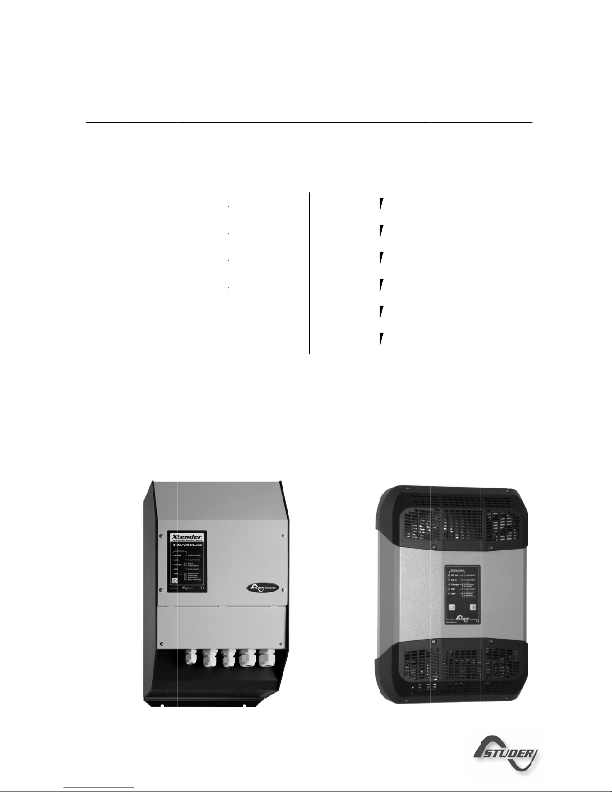
1 INTRODUCTION
Congratulations! You are about to install and use a device from the Xtender range. You have
chosen a high-tech device that will play a central role in energy saving for your electrical
installation. The Xtender has been designed to work as an inverter / charger with advanced
functions, which can be used in a completely modular way and guarantee the faultless functioning
of your energy system.
When the Xtender is connected to a generator or network, the latter directly supplies the
consumers, and the Xtender works like a battery charger and backup device if necessary. The
powerful battery charger has an exceptional high efficiency and power factor correction (PFC)
close to 1. It guarantees excellent battery charging in all situations. The charge profile is freely
configurable according to the type of battery used or the method of usage. The charge voltage is
corrected depending on the temperature, thanks to the optional external sensor. The power of the
charger is modulated in real time dependent according to the demand of the equipment
connected at the Xtender output and the power of the energy source (network or generator). It
can even temporarily backup the source if the consumer demand exceeds the source capacity.
The Xtender continuously monitors the source to which it is connected (network or generator) and
disconnects itself immediately if the source is missing, disturbed or does not correspond to the
quality criteria (voltage, frequency, etc.). It will then function in independent mode, thanks to the
integrated inverter. This inverter, which has an extremely robust design, benefits from STUDER
Innotec’s many years of experience and expertise in this area. It could supply any type of load
without faults, enjoying reserves of additional power that is unmatched on the market. All your
equipment will be perfectly provided with energy and protected from power outages in systems
where energy supply is unpredictable (unreliable network) or voluntarily limited or interrupted, such
as hybrid installations on remote sites or mobile installations.
The parallel and/or three-phase network operation of the Xtender offers modularity and flexibility
and enables optimum adaptation of your system to your energy requirements.
The RCC-02/03 control, display and programming centre (optional) enables optimum configuration
of the system and guarantees the operator continuous control for all important configurations in
the installation.
In order to guarantee perfect commissioning and functioning of your installation, please read this
manual carefully. It contains all the necessary information relating to the functioning of the inverters
/ chargers in the Xtender series. The setting up of such a system requires special expertise and may
only be carried out by qualified personnel familiar with the applicable local regulations.
2 GENERAL INFORMATION
2.1 OPERATING INSTRUCTIONS
This manual is an integral part of each inverter/charger from the Xtender series.
It covers the following models and accessories
1
:
Inverter/charger: XTH 3000-12 – XTH 5000- 24 – XTH 6000-48 – XTH 8000-48
Inverter/charger: XTM 1500-12, XTM 2000-12, XTM 2400-24,
XTM 3500-24, XTM 2600-48, XTM 4000-48
Temperature sensor: BTS-01
Remote command module: RCM-10
For greater clarity, the device is referred to in this manual as Xtender, unit or device, when the
description of its functioning applies indiscriminately to different Xtender models.
These operating instructions serve as a guide line for the safe and efficient usage of the Xtender.
Anyone who installs or uses an Xtender can rely completely on these operating instru ctions, and is
bound to observe all the safety instructions and indications contained. The installation and
commissioning of the Xtender must be entrusted to a qualified professional. The installation and
1
Also for 120Vac model (-01)
Page 6

STUDER Innotec
Xtender
4 V.3.1.0 User manual
usage must conform to the local safety instructions and applicable standards in the country
concerned.
2.2 CONVENTIONS
This symbol is used to indicate the presence of a dangerous voltage that is sufficient to
constitute a risk of electric shock.
This symbol is used to indicate a risk of material damage.
This symbol is used to indicate information that is important or which serves to optimise
your system.
All values mentioned hereafter, followed by a configuration no. indicate that this value may be
modified with the help of the RCC-02/03 remote control.
In general, the default values are not mentioned and are replaced by a configuration no. in the
following format: {xxxx}. The default values for this configuration are specified in the configuration
table, p. 40.
All configuration values modified by the operator or installe r must be transferred into the
same table. If a parameter not appearing in the list (advanced configurations) has been
modified by an authorised person with technical knowledge, they will indicate the
number of the modified parameter(s), the specifications of the configuration(s) and the
new value set, at the end of the same table.
All figures and letters indicated in brackets refer to items of figures in the separate manual
“Appendix to the installation and operating instructions” supplied with the device.
The figures in brackets refer to elements belonging to the Xtender.
The uppercase letters in brackets refer to AC cabling elements.
The lowercase letters in brackets refer to battery cabling elements.
2.3 QUALITY AND WARRANTY
During the production and assembly of the Xtender, each unit undergoes several checks and tests.
These are carried out with strict adherence to the established procedures. Each Xtender has a
serial number allowing complete follow-up on the checks, according to the particular data for
each device. For t his reason it is very important never to remove the type plate (appendix I – fig.
3b) which shows the serial number. The manufacture, assembly and tests for each Xtender are
carried out in their entirety by our factory in Sion (CH). The warrant y for this equipment depends
upon the strict application of the instructions appearing in this manual.
The warranty period for the Xtender is 2 years.
2.3.1 Exclusion of warranty
No warranty claims will be accepted for damage resulting from handling, usage or processing that
does not explicitly appear in this manual. Cases of damage arising from the following causes are
notably excluded from the warranty:
Surge voltage on the battery input (for example, 48 V on the battery input of an XTH 3000-12)
Incorrect polarity of the battery
The accidental ingress of liquids into the device or oxidation resulting from condensation
Damage resulting from falls or mechanical shocks
Modifications carried out without the explicit authorisation of Studer Innotec
Nuts or screws that have not been tightened sufficiently during the installation or maintenance
Damage due to atmospheric surge voltage (lightning)
Page 7
STUDER Innotec
Xtender
User manual V.3.1.0 5
Damage due to inappropriate transportation or packaging
Disappearance of original marking elements
2.3.2 Exclusion of liability
The placement, commissioning, use, maintenance and servicing of the Xtender cannot be the
subject of monitoring by Studer Innotec. For this reasons we assume no responsibility and liability for
damage, costs or losses resulting from an installation that does not conform to the instructions,
defective functioning or deficient maintenance. The use of a Studer Innotec inverter is the
responsibility of the customer in all cases.
This equipment is neither designed nor guaranteed to supply installations used for vital medical
care nor any other critical installation carrying significant potential damage risks to people or the
environment.
We assume no responsibility for the infringement of patent rights or other rights of third parties that
result from using the inverter.
Studer Innotec reserves the right to make any modifications to the product without prior
notification.
2.4 WARNINGS AND NOTES
2.4.1 General
This manual is an integral part of the device and must be kept available for the operator
and installer. It must remain close to the insta llation so that it may be consulted at any
time.
The configuration table available at the end of the manual (p. 40) must be kept up to date in the
event of modification of the configurations by the operator or installer. The person in charge of
installation and commissioning must be wholly familiar with the precautionary measures and the
local applicable regulations.
When the Xtender is running, it generates voltage that can be potentially lethal. Work on
or close to the installation must only be carried out by thoroughly trained and qualifie d
personnel. Do not attempt to carry out ongoing maintenance of this product yourself.
The Xtender or the generator connected to it may start up automatically under certain
predetermined conditions.
When working on the electrical installation, it is important to be certain that the source of
DC voltage coming from the battery as well as the source of AC voltage coming from a
generator or network have been disconnected from the electrical installation.
Even when the Xtender has been disconnected from the supply sources (AC and DC), a
dangerous voltage may remain at the outputs. To eliminate this risk you mu st switch the
Xtender OFF using the ON/OFF button (1). After 10 seconds the electronics is discharged
and intervention may take place without any danger.
All elements connected to the Xtender must comply with the applicable laws and regula tions.
Persons not holding written authorisation from Studer Innotec are not permitted to proceed with
any change, modification or repairs that may be required. Only original parts may be used for
authorised modifications or replacements.
This manual contains important safety information. Read the safety and working instructions
carefully before using the Xtender. Adhere to all the warnings given on the device as well as in the
manual, by following all the instructions with regard to operation and use.
The Xtender is only designed for indoor use and must under no circumstances be subject ed to rain ,
snow or other humid or dusty conditions.
The maximum specifications of the device shown on the type plate, as at fig. 1b , must be adhered
to.
Page 8

STUDER Innotec
Xtender
6 V.3.1.0 User manual
In the event of use in motorised vehicles, the Xtender must be protected from dust , splash water
and any other humid condition. It must also be protected from vibration by installing absorbent
parts.
2.4.2 Precautions for using the batteries
Lead-acid or gel batteries produce a highly explosive gas with normal use. No source of sparks or
fire should be present in the immediate vicinity of the batteries. The batteries must be kept in a wellventilated place and be installed in such a way as to avoid accidental short-circuits when
connecting.
Never try to charge frozen batteries.
When working with the batteries, a second person must be present in order to lend assistance in the
event of problems.
Sufficient fresh water and soap must be kept to hand to allow adequate and immediate washing
of the skin or eyes affected by accidental contact with the acid.
In the event of accidental contact of the eyes with acid, they must be washed carefully with cold
water for 15 minutes. Then immediately consult a doctor.
Battery acid can be neutralised with baking soda. A sufficient quantity of baking soda must be
available for this purpose.
Particular care is required when working close to the batteries with metal tools. Tools such as
screwdrivers, open-ended spanners, etc. may cause short-circuits. Consequently occurring sparks
may cause the battery to explode.
When working with the batteries, all metal jewellery such as rings, bracelet watches, earrings, etc.,
must be taken off. The current output by the batteries during a short-circuit is sufficie ntly powerful to
melt the metal and cause severe burns.
In all cases, the instructions of the battery manufacturer must be followed carefully.
3 ASSEMBLY AND INSTALLATION
3.1 HANDLING AND MOVING
The weight of the Xtender is between 35 and 50kg depending upon the model. Use an appropriate
lifting method as well as help from a third party when installing the equipment.
3.2 STORAGE
The equipment must be stored in a dry environment at an ambient temperature of between
-20°C and 60°C. It stays in the location where it is to be used a minimum of 24 hours before being
set up.
3.3 UNPACKING
When unpacking, check that the equipment has not been damaged during transportation and
that all accessories listed below are present. Any fault must be indicated immediately to the
product distributor or the contact given at the b ack of thi s manual.
Check the packaging and the Xtender carefully.
Standard accessories:
Installation and operating instructions, c.f. Appendix 1
Mounting plate – fig. 2a (18)
2 conduit glands for the battery cable
3.4 INSTALLATION SITE
The installation site for the Xtender is of particular importance and must satisfy the following criteria:
Protected from any unauthorised person.
Protected from water and dust and in a place with no condensation.
Page 9
STUDER Innotec
Xtender
User manual V.3.1.0 7
It must not be situated directly above the battery or in a cabinet with it.
No easily inflammable material should be placed directly underneath or close to the Xtender.
Ventilation apertures must always remain clear and be at least 15cm from any obstacle that may
affect the ventilation of the equipment according to fig. 2b.
In mobile applications it is important to select an installation site that ensures as low a vibration lev el
as possible.
3.5 FASTENING
The Xtender is a heavy unit and must be mounted to a wall designed to bear such a
load. A simple wooden panel is insufficient.
The Xtender must be installed vertically with sufficient space around it to guarantee adequate
ventilation of the device (see figs. 2a and 2b).
3.5.1 Fastening XTH model
Firstly fix the mounting bracket (18)) supplied with the device using 2 Ø < 6-8 mm >screws**.
Then hang the Xtender on the bracket. Fasten the unit permanently using 2 Ø <6-8 mm> screws**
on to the two notches located at the underside of the case.
3.5.2 Fastening XTM model
Screw on a solid wall (concrete or metallic wall) an M8 screw without washer up to a distance of
1.6 mm of the wall.
Hang the apparatus by having care to release beforehand the trap door of access (17) by
inserting it inside the apparatus using a screwdriver, if you estimate that a complete tightening of
this point of fixing is necessary. In theory complete tightening is necessary only in the mobile
installations.
Dismount the lower plastic cap of the apparatus giving access to the compartment of wiring.
Carefully fix the apparatus with two screws (Ø 6-8 mm) in the two clamp holes (16) inside the
compartment of wiring.
If the Xtender is installed in a closed cabinet this must have sufficient ventilation to guarantee an
ambient temperature that conforms to the operation of the Xtender.
**: These items are not delivered with the device.
It is imperative to ensure complete and safe fastening of the device. A device that is
simply hung may detach and cause severe damage.
In motor vehicles or when the support may be subject to strong vibrations, the Xtender must be
mounted on anti-vibration supports.
3.6 CONNECTIONS
3.6.1 General recommendations
The Xtender falls within protection class I (has a PE connection terminal). It is vital that a protective
earth is connected to the AC IN and/or AC OUT PE terminals. An additional protective earth is
located between the two fastening screws at the bottom of the unit (fig. 2b-(17)).
Page 10

STUDER Innotec
Xtender
8 V.3.1.0 User manual
In all cases, the PE conductor for the equipment must at least be connected to the PE
for all equipment in protection class I upstream and downstream of the Xtender
(equipotential bonding). It is mandatory that the legislation in force for the application
concerned be adhered to.
Tighten of the input (13) and output (14) terminals by means of a no. 3 screwdriver and those for
the “REMOTE ON/OFF” (7) and “AUX.CONTAC” (8) by means of a no. 1 screwdriver.
The cable sections of these terminals must conform to local regulations.
All connection cables as well as the battery cables must be mounted using cable restraints in order
to avoid any traction on the connection.
Battery cables must also be as short as possible and the section must conform with the applicable
regulations and standards. Sufficiently tighten the clamps on the “battery” inputs (fig. 4a (11) and
(12)).
Page 11
STUDER Innotec
Xtender
User manual V.3.1.0 9
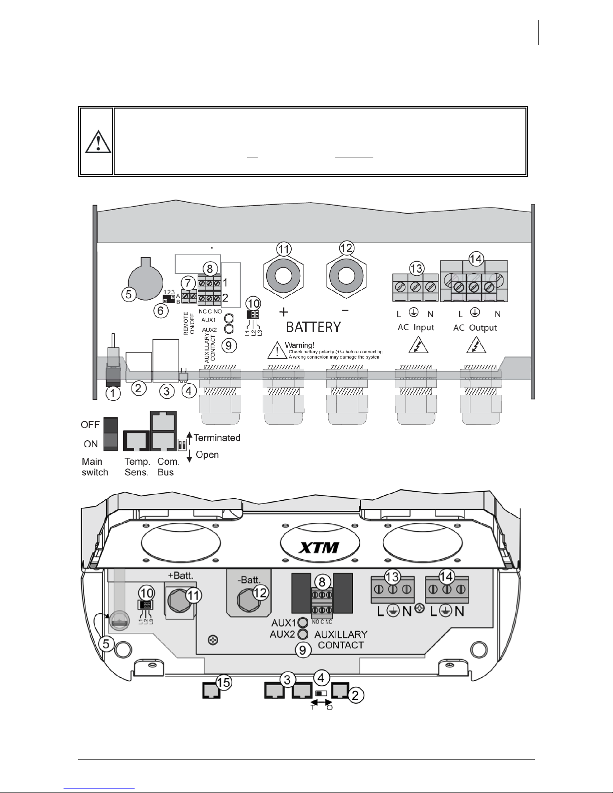
3.6.2 Device connection compartment
The unit’s connection compartment must remain permanently closed when in operation.
It is imperative to close the protection cap on the connection terminals after each
intervention in the device.
After opening, check that all
sources of AC and DC voltage (batteries) have been
disconnected or put out of service.
Page 12

STUDER Innotec
Xtender
10 V.3.1.0 User manual
Pos. Denomination Description Comment
1
ON/OFF
Main switch
Main on/off switch
See chapter 7.1 - p 29.
In XTM series, this function is deported on
the remote command module RCM-10.
See chap.6.4.3 – p.28
2 Temp. Sens
Connector for the battery
temperature sensor
See chapter 6.4.2 – p. 28.
Only connect the original Studer BTS-01
sensor
3 Com. Bus
Double connector for
connecting peripherals such as
the RCC002/03 or other
Xtender units
See chapter 4.5.9 – p. 17.
The two termination switches (4) for the
communication bus both remain in
position T (terminated) except when
both conn ectors are in use.
4
O / T
(Open /
Terminated)
Switch for terminating the
communication bus.
5 --
3.3 V (CR-2032) lithium ion type
battery socket
Used as a permanent supply for the
internal clock. See chapter The real time
clock 6.2.11 - p 25.
6 --
Jumper for programming the
off/on switch by dry contact
See chapter 6.2.12 – p. 24 and fig. 8b
point (6) and (7). They are positioned at
A-1/2 and B-2/3 by default
7
REMOTE
ON/OFF
Entry com mand terminals..
In XTM series, this entry is
deported on the remote
command module RCM-10.
See chap. 6.4.3 – p. 28
Allow to dive a function – to be defined
by programming – by the closing of a dry
contact or by the presence of a voltage
across these terminals. See chapter
6.2.12– p. 24).
8
AUXILLARY
CONTACT
Auxiliary contact (See chapter 6.2.10– p. 24)
Take care not to exceed the admissible
loads
9 --
Activation indicators for
auxiliary contacts 1 and 2
See chapter 6.2.10– p. 24
10 L1/L2/L3
Phase selection jumpers. See chapter 6.3.1. – p.26.
Jumper default at position L1
11 +BAT
Positive pole battery
connection terminals
Carefully read chapter 4.5 – p.14
Take care with the polarity of the battery
and when ti g htening the clamp.
12 -BAT
Negative pole battery
connection terminals
13 AC Input
Connection terminals for the
alternative power supply
(generator or public network)
See chapter 4.5.7 - p. 17.
Note: It is imperative that the PE terminal
be connected.
14 AC Output
Connection terminals for the
device output.
See chapter 4.5.6 - p. 17.
Note: Increased voltages may appear
on the terminals, even in the absence of
voltage at the input of the inverter.
15 RCM-10 Connector for RCM-10 module Only on XTM. See chap. 6.4.3 – p.28
4 CABLING
The connection of the Xtender inverter / charger is an important installation step.
It may only be carried out by qualified personnel and in accordance with the applicable local
regulations and standards. The installation must always comply with these standards.
Pay attention that connect ions are completely tightened and th at each wire is connected at the
right place.
Page 13
STUDER Innotec
Xtender
User manual V.3.1.0 11
4.1 CHOICE OF SYSTEM
The Xtender may be used in different system types, each of which must meet the standards and
particular requirements associated with the application or site of installation. Only an appropriately
qualified installer can advise you effectively on the applicable standards wit h regard t o the various
systems and the country concerned.
Examples of cabling are presented in appendix I of this manual, fig. 5 and following. Please
carefully read the notes associated with these examples in the tables on p. 33 and following.
4.1.1 Hybrid type stand-alone systems
The Xtender can be used as a primary supply system for grid-remote sites where a renewable
energy source (solar or hydraulic) is generally available and a generator is used as backup. In this
case, batteries are generally recharged by a supply source such as solar modules, wind power or
small hydropower systems. These supply sources must have their own voltage and/or current
regulation system and are connected directly to the battery. (Example, fig. 11)
When the energy supply is insufficient, a generator is used as a back-up energy source. This allows
the batteries to be recharged and direct supply to consumers via the Xtender transfer relay.
4.1.2 Grid-connected emergency systems
The Xtender can be used as an emergency system, also known as an uninterruptible power supply
(UPS) – enabling a reliable supply to a site connected to an unreliable network. In the event of an
interruption to the energy supply from the public network, the Xtender, connected to a battery,
substitutes the faulty source and enables a support supply to the users connected downstream.
These will be supplied as long as the energy stored in the battery allows. The battery will quickly be
recharged at the next reconnection to the public grid.
Various application examples are described in figs. 8a – 8c in appendix I.
The use of the Xtender as a UPS must be carried out by qualified personnel who have
been checked by the responsible local authorities. The diagrams in the appendix are
given for information and as a supplement. The applicable local standards and
regulations must be adhered to.
4.1.3 Integrated mobile systems
These systems are meant to be temporarily connected to the grid and ensure the supply of the
mobile system when this is disconnected from the grid. The main applications are for boats, service
vehicles and leisure vehicles. In these cases, two separate AC inputs are often required, one
connected to the grid and the other connected to an on-board generator. Switching between
two sources must be carried out using an automatic or manual reversing switch, conforming to the
applicable local regulations. The Xtender has a single AC input.
Various application examples are described in figs. 10a – 10b – 10c).
4.1.4 Multi-unit systems
Whatever system is selected, it is possible to realise systems composed of several units of the same
type and the same power output. Up to three Xtenders in parallel or three extenders forming a
three-phase grid or three times two or three Xtenders in parallel forming a three-phase / parallel
grid, may be thus combined.
4.2 EARTHING SYSTEM
The Xtender is a protection class I unit, which is intended for cabling in a grid type TT, TN-S or TNC-S.
The earthing of the neutral conductor (E) is carried out at a sole installation point, upstream of the
RCD circuit breaker (D).
Page 14
STUDER Innotec
Xtender
12 V.3.1.0 User manual
The Xtender can be operated with any earthing system. In all cases it is imperative that the
protective earth be connected in compliance with the applicable standards and regulations. The
information, notes, recommendations and diagram mentioned in this manual are su bject to local
installation regulations in every case. The installer is responsible for the conformity of the installation
with the applicable local standards.
4.2.1 Mobile installation or installation connected to the grid via plug
connector
When the input of the device is connected directly to the grid via a plug, the length of the cable
must not exceed 2 m and the plug must remain accessible.
In the absence of voltage at the input, the neutral and live are interrupted, thereby guaranteeing
complete isolation and protection of the cabling upstream of the Xte nder.
The earthing system downstream of the Xtender is determined by the upstream earthing system
when the grid is present. In the absence of the grid, the earthing system downstream of the inverter
is in isolated mode. The safety of the installation is guaranteed by the equipotential bonding.
The connection (link) between the neutrals (C) upstream and downstream of the
Xtender is not permitted in this configuration.
This connection type guarantees the optimal continuity for supplying the Xtender loads. The first
isolation fault will not lead to an interruption in the supply.
If the installation requires the use of a permanent isolation controller this would have to be deactivated when the TT network is present at the Xtender input.
All sockets and protection class I devices connected downstream of the Xtender must
be properly connected to the earth (earthed socket). The cabling rules above remain
valid, including in installations, in all cases where the Xtender input is connected to the
grid via a plug connector.
4.2.2 Stationary installation
The installation may be equiva lent to a mobile installation (with interrupted neutral).
In a fixed installation where the neutral is connected to the earth at a single installation point
upstream of the Xtender, it is permissible to carry out a connection of the neutrals in order to
preserve an unchanged earthing system downstream, independent of the operating mode of the
Xtender. This choice has the advantage of keeping the protection devices downstream of the
Xtender. This connection can be executed according to the examples in appendix 1, or carried
out by modifying the configuration {1486}
In this case the appearance of the first fault will lead to the installation stopping or the
disconnection of the protection devices upstream and/or downstream of the Xtender.
Safety is guaranteed by the equipotential bonding and by any RCD circuit-breakers placed
downstream.
This connection (C) is not permitted if a socket is installed upstream of the Xtender.
4.2.3 Installation with automatic PE-neutral switching
In certain applications, it is desirable to keep the neutral upstream and downstream of t he Xtender
separated (C) while re-establishing the earthing system (TN-S, TT or TNC-S) in the absence of voltage
at the input. This can be programmed by the configuration {1485} via the RCC-02/03 remote
control. This modification must be carried out possessing technical knowledge, at the responsibility
of the installer and in conformity with the applicable regulations and standards.
This allows adherence to the requirements for an earth-neutral connection at the source.
Page 15
STUDER Innotec
Xtender
User manual V.3.1.0 13
4.3 RECOMMENDATIONS FOR DIMENSIONING THE SYSTEM
4.3.1 Dimensioning the battery
The battery capacity is dimensioned according to the requirements of the user – that is 5 to 10
times its average daily consumption. The discharge depth of the battery will therefore be limited
and the service life of the battery will be extended.
On the other hand, the Xtender must have a battery capacity that is large enough to be able to
take full advantage of the performance of the equipment. The minimum capacity of the batteries
(expressed in Ah) is generally dimensioned in the following way: five times the rated power output
of the Xtender / the battery voltage. For example, the model XTH 8048 must have a battery of a
minimum capacity of 7000*5/48=730 Ah (C 10). Because of the inverter’s extreme overload
capacity, it is often recommended that this value be rounded up. An under-dimensioned battery
may lead to an accidental and undesired stopping of the Xtender in the event of high instances of
use. This stoppage will be due to a voltage that is insufficient on the battery, subject to a strong
discharge current.
The battery will be selected with regard to the greatest value resulting from the calculations set out
above.
The battery capacity determines the adjustment of the configuration {1137} “battery charge
current”. A value between 0.1 and 0.2 x C batt. [Ah] (C10) enables an optimum charge to be
guaranteed.
The method proposed below is strictly indicative and in no way constitutes a guarantee
of perfect dimensioning. The installer is solely responsible for good dimensioning and
installation
4.3.2 Dimensioning the inverter
The inverter is dimensioned in such a way that the rated power output covers the power of all the
consumers which will be used at the same time. A dimensioning margin of 20 to 30% is
recommended to guarantee that the Xtender will work well in an ambient temperature of more
than 25 °C.
4.3.3 Dimensioning the generator
The power output of the generator must be the same or more than the average daily power.
Optimally, it should be two or three times this power. Thanks to the smart boost function it is not
necessary to over-dimension the generator. Indeed, the loads those are temporarily higher than
the power of the generator will be supplied by the inverter. Ideally it should not have a power
output by phase that is less than half of the power of the Xte nder(s) present at this phase.
The power available downstream of the inverter when the generator is working is the
same as the sum of the two powers.
4.3.4 Dimensioning the renewable energy sources
In a hybrid system, the alternative energy sources such as the solar generator, wind power and
small hydropower should, in principle, be dimensioned in such a way as to be able to cover the
average daily consumption.
Page 16

STUDER Innotec
Xtender
14 V.3.1.0 User manual
4.4 WIRING DIAGRAMS
4.5 C
ONNECTING THE BATTERY
Lead batteries are usually available in 2 V, 6 V or 12 V block types. In the majority of cases, in order
to obtain an operating voltage that is correct for Xtender usage, several batteries must be
connected in series or in parallel depending on the circumstances.
The various cabling options are presented in figures 5a-5b (12 V), 5c-5e (24 V) and 6a to 6d (48 V) in
appendix I of this manual.
4.5.1 Battery cable cross-section and DC protective devices
The battery cables must also be as short as possible.
It is always preferable to keep the cable at the negative pole of the battery as short as possible.
In order to avoid any furthe r loss and protection redundancy, the XTH doe s not have an internal
fuse.
A protective device (f) must be instal led as close as possible to the battery and sized according to
the below table.
The recommended cable cross-sections are valid
for lengths less than 3 m. beyond this length it is
strongly recommended oversize the battery
cables.
The diagrams shown in the appendix of this document are subsidiary. The applicable
local installation regulations and standards must be adhered to.
The elements referred to with an uppercase letter denote the alternate current (AC)
part.
The elements referred to with a lowercase letter denote the direct current (DC) part.
In multi-unit systems, all Xtenders from the same system must be connected according to
the same battery bank.
The battery cables must be protected by one of the following measures in all cases:
- protection device (fuse) at each pole
- protection device (fuse) on the pole not connected to the earth
Range Battery side fuse
Section of
cable (<3m)
XTM-4000-48 200A 50mm2
XTM-2600-48 100A 25mm2
XTM-3500-24 300A 70mm2
XTM-2400-24 200A 50mm2
XTM-2000-12 300A 70mm2
XTM-1500-12 250A 70mm2
XTH-8000-48 30 0A 95mm2
XTH-6000-48 300A 70mm2
XTH-5000-24 300A 95mm2
XTH-3000-12 350A 95mm2
Page 17

User manu
Th
In
s
For safety
r
For mobile
4.5.2 C
o
Insert the
c
the cable
cable. Fix
screws mu
s
On XTM ra
following t
h
4.5.3 F
u
A fuse del
i
the batter
y
The prese
n
breaker) a
B
e
w
h
4.5.4 B
a
B
eusi
In
c
Prepare t
h
good con
d
Fasten the
open prot
e
W
h
Th
iev
al
e clamps
m
ufficient ti
g
easons, w
e
installation
nnectin
onduit gla
clamps an
d
the batter
y
t be very
w
nge, you c
a
e below p
se mou
n
vered with
respectin
g
ce of this
s close as
p
careful w
i
ich must fi
t
ttery-si
d
fore conn
e
ng a voltm
orrect pol
a
e batteries
itions with
negative
c
ction devi
c
en conne
c
s spark is n
o
en if the u
n
ust be car
e
htening m
a
recomme
n
the conne
c
g the ba
nds supplie
fasten th
e
cables to
ell tighten
e
n insert , i
f
rocedure.
ting on
b
the unit (
X
the belo
w
fuse does
ossible of t
h
th the orie
n
into the c
a
e conn
e
cting the
b
eter.
rity or surg
e
for conne
c
correctly fi
t
able on to
e (f).
ting the
b
rmal and
it is halted
b
fully fixed
a
y cause d
a
d an ann
u
tions shou
l
ttery (Xt
e
d on the b
a
conduit
g
the appro
p
d.
required,
a
attery p
TM) can b
e
stacking o
not exemp
e battery.
tation of
t
ble lug’s h
o
ction
attery, ca
r
voltage
m
tion: appr
o
ted clamp
s
the negati
attery, a s
p
due to the
y the mai
n
V.3.1.0
nd tighte
n
ngerous h
e
al check o
n
d be chec
k
nder sid
ttery cabl
e
land on th
e
riate conn
fuse direc
ositive p
o
mounted
rder.
t an install
a
he cerami
c
le.
efully che
c
ay seriousl
y
priate ba
t
.
ve pole (-)
ark may
o
load of th
e
on off co
m
ed sufficie
n
ating at t
h
the tightn
ed more f
r
e)
before ti
g
device. R
ections „+
tly on the
p
le (XTM
directly o
n
tion of a
p
washer.
T
k the volt
a
damage
t
tery clam
p
of the batt
e
ccur whe
n
internal fil
mand (1).
tly to guar
a
e connecti
ess of all c
o
equently f
o
htening th
epeat this
f
Battery “a
n
ositive co
n
only)
the positi
v
rotective
d
here is a s
m
ge and p
o
he device
.
s, protecti
o
ry and th
e
connecti
n
tering cap
a
a =
b =
c =
d =
e =
S
TUDE
R
ntee mini
m
on point.
nnections.
r tightness.
e cable cl
a
or the sec
o
d „- Batter
y
nection to
e connec
t
evice (fu
s
all lip on
larity of th
e
n device
(
positive c
a
g the sec
o
city of th
e
bolt M8 x
3
washer
ceramic w
M10 cable
fusible
Innote
c
Xtende
r
1
5
um loss.
mp. Crim
p
nd batter
y
“. The M
8
the batter
y
ing pole t
o
e or circui
t
one side
battery
f), cable i
n
ble on th
e
nd pole.
Xtender
0)
ashe
r
lug
Page 18

S
TUDER
Xtender
16
The defau
l
configurat
02/03 rem
o
responsibl
e
If the fact
o
40 of this
m
battery or
The cabli
n
qualified
p
etc. must
b
under con
s
4.5.5 E
a
One of th
e
pole. In a
standards
In case of
the batter
y
case the
u
the front o
f
4.5.6 C
o
Hi
gtheter
The 230 V
c
section co
1a). Distrib
a distributi
o
The Xtend
e
N = neutra
= prot
e
D
ude
su
th
eind
n
o
If the assis
t
for the out
or at the
current of
t
A
v
a
mba
Innotec
t values of
ion table p
te control
for defaul
t
ry settings
a
anual. The
gel batteri
e
g and co
n
rofessional
.
e adapte
ideration.
rthing t
h
two batt
e
ll cases th
e
associated
earthing, t
conduct
o
se of the
a
the devic
e
nnectin
h voltage
s
inverter i
s
minals an
d
onsumers
nforming t
o
ution must
c
n table.
r terminals
l, L = live
ctive earth
e to the s
vice may
b
pplied by t
dimensi
o
icated on
minal curr
e
ance func
t
put (F) will
b
maximum
v
he inverte
r
s of the c
o
lues of t
anufactur
e
tteries.
the batter
y
.40. If they
before co
n
values no
t
re modifie
default va
s (VRLA or
A
nection o
f
The install
a
d and mus
t
e batter
y
ry condu
c
installati
o
with the a
p
he earthin
g
r. The eart
h
dditional
e
between
g the co
may be p
r
deactivat
e
battery te
r
must be c
o
the stand
a
onform to
are marke
d
(connect
e
ource assis
e higher t
h
he additio
n
ning of th
the prote
c
nt of the in
ion at the
e establis
h
alue of th
.
nnection
o
he Xtend
e
r. Non-con
’s charge
t
prove not
t
necting th
e
correspon
d
d, the new
lues propo
s
GM).
the install
a
tion mate
r
conform
t
tors can b
e
n must co
plication.
conduct
o
ing of the
e
arthing sc
r
the two lo
w
nsumers
esent on t
h
d and th
a
minals, bef
nnected o
rds with re
g
the local s
t
in the foll
o
d to the en
tance fun
c
an the rat
al source
a
e output
c
tion devi
c
verter. (Se
e
source (sm
a
ed at a m
a
e protecti
o
f the batt
e
r are co
n
forming val
V.3.1.0
hreshold l
e
o conform
voltage s
o
ing with t
h
values mu
s
ed by Stud
tion shoul
ial such as
o the appl
earthed.
nform to t
h
r section
m
quipment
ew is reco
m
er fastenin
g
at the 2
3
e connect
t there is n
o
ore procee
n the “AC
O
ard to the
andards a
n
wing way:
closure of t
tion (smar
t
ed current
nd the cu
r
ables will
e (H) loc
a
fig. 1a an
d
rt boost) i
s
ximum val
n device
a
ry, it is n
e
form to
ues may b
e
vel are sh
o
, it is neces
urces on t
h
e recomm
e
t be entere
er Innotec
a
d only be
cables, co
n
icable law
s
This may
b
e local r
e
ust at leas
must also
a
mended
screws.
0 V AC
o
ion termin
a
AC or D
C
ding with t
h
UT” (14)
c
rated curr
e
d regulati
o
he device)
.
boost) th
e
of the inv
e
rent suppli
e
be carrie
d
ted on th
e
chap. 6.2.
not used,
ue equal t
o
t the inp
u
cessary to
the reco
m
dangero
u
wn in fig. 3
sary to mo
d
e AC inpu
ndations
o
d on the c
o
re the usu
carried ou
t
nectors, d
i
and regul
e either th
gulations
a
t be equiv
a
dhere to t
h
(fig. 2 b (17
)
utput
ls (13) and
voltage p
e connec
t
onnection
nt at the X
ns, and ge
current
a
rter. It is th
e
d by the i
out by
a
upstream
6 – p. 23)
the size of
the rated
t (H) if this
check tha
mendatio
n
s and/or s
e
U
a and spe
c
ify them
v
t. Studer In
n
f the man
u
nfiguration
al values f
o
by an a
p
stribution
b
ations the
a
e positive
o
nd usage
lent to th
e
ese regula
), which is
(14). Make
resent on t
h
ion.
terminals
w
tender out
p
nerally, be
t the outp
u
sum of th
e
nverter. In
t
dding th
e
of the un
the protec
t
current of
t
is exceed
s
t the confi
s of the
riously da
m
ser manua
l
ified in th
e
ia the RC
C
otec is no
t
facturer.
table on p
.
r lead aci
d
propriatel
y
oxes, fuses
,
pplicatio
n
r negativ
e
or specifi
c
section o
f
tions. In thi
s
located a
t
sure that
e AC IN
ith the wir
e
ut (see fig
.
realised vi
a
t of the
current
his case,
current
t, to the
ion devic
e
he inverter
,
the rate
d
guration
battery
age the
Page 19

User manu
A
nbode
a
c
oonba
4.5.7 C
o
The Xtend
e
generator
.
Xtender s
p
The sourc
e
section, d
e
the appro
p
on the typ
e
N = neutra
= prot
e
4.5.8
W
These con
t
for these c
near the t
e
cabling of
this manu
a
The factor
y
4.5.9 C
o
The Xtend
communi
c
Innotec. In
The length
In a syste
conducte
d
The com
m
unit appli
c
Innotec. I
n
connect t
h
Th
p
othi
in
4.5.10 C
o
The temp
e
connecte
d
correspon
d
socket (2)
directly n
e
made im
m
al
additiona
ttom of th
e
vice, parti
c
three-wire
nnection
c
e of the p
o
ttery cabl
e
nnectin
r is intend
e
Check th
a
ecified on
t
must be
c
pending
o
riate calib
plate (fig
.
l, L = live
ctive earth
iring au
x
acts are r
e
ontacts ar
e
rminals co
r
these auxil
l.
-set functi
o
nnectin
er is equip
ation bus
f
this netwo
r
of the co
m
m compris
i
without st
o
unication
b
ation or t
o
these cas
e
e units via
e 2 switch
e
sition T (te
r
s case, bot
use, the tw
o
nnectin
rature sen
s
or disco
ing socke
until they c
xt to it. Th
ediately.
l earthing t
e
unit. It ca
ularly whe
n
cable (li
v
ables of th
e
les of the
b
.
g the A
C
d to be s
u
t the rated
he type pl
a
onnected
n the pow
e
re. This will
b
3b). The t
e
(connect
e
iliary co
n
versing co
n
16 A: 250
V
responds t
o
iary contra
c
ns for thes
e
g the co
ped with
a
or differen
k all partie
s
municatio
n
ng a singl
pping the
us will be
u
connect
o
s, the insta
the comm
u
s for the
c
minated) e
h must be
p
terminati
o
g the te
m
or, BTS-01 i
s
nnected
a
t (2) mark
e
lick in. The
t
e tempera
rminal (15
n be used
i
cable cr
o
e, earth
a
input an
d
attery. PE r
supply
s
pplied by
a
voltage of
te (fig. 3b)
to the inp
u
r output o
e at the
m
rminals are
d to the en
tacts
tacts that
a
AC/24VD
C
the statu
s
ts depen
d
2 auxiliar
y
mmunic
a
pair of R
J
t consume
r
in the net
w
bus cabl
e
e Xtender,
Xtender (h
o
sed to int
e
ther types
llation mus
t
nication b
u
ommunic
a
xcept whe
n
laced in t
h
n switches
peratur
e
supplied
w
t any tim
e
d “Temp.
emperatur
ture senso
r
V.3.1.0
) is present
nstead of
a
ss-sections
nd neutr
a
output (A
C
equired usi
n
ources
lternative
the source
.
t terminals
f the sourc
e
aximum e
q
marked in
closure of t
re potenti
or 3 A: 50
of the co
n
s solely on
contacts
a
tions c
a
45/8 conn
types whi
ork are co
must not e
the conn
e
t plug).
rconnect
o
of users
w
be switch
e
s.
tion bus t
e
both con
e O open
p
(14) will be
sensor
ith a 3 m
c
(includin
Sens.” on
e sensor sl
e
will be re
c
between t
connecti
o
used at th
e
l) throug
h
IN and A
C
g same or
oltage so
u
correspon
d
marked “
A
, and pro
t
ual to the
the followi
n
he device)
.
al-free. The
VDC max.
T
tact in idle
the applic
a
re covere
d
bles
ectors that
ch have t
h
nnected in
xceed 300
ction of
t
ther Xtend
e
ho have t
h
d off using
rmination,
nectors ar
e
osition. If
o
in position
T
(BTS-01)
able fitted
g when t
h
the Xtend
e
eve may si
m
ognised
a
he two fas
t
n on the i
n
output do
the con
d
OUT), or
w
greater cr
o
rces such
a
s to the ra
t
C INPUT” (
ected by
a
current I A
C
g way:
admissible
he repres
e
mode (lig
h
tion and c
in the cha
allow info
e propriet
a
series (cha
m.
he RCC-0
2
r inverters
e propriet
a
the main “
“Com. Bus
"
in use. In t
h
ne of the t
w
.
with RJ11/
6
e device
r. Plug th
e
ply be st
u
utomatical
S
TUDE
R
ening scre
w
put termin
a
not allow t
uit gland
s
hen the e
a
ss-sections
s the pub
l
ed voltag
e
13) with su
f
protectio
n
in max (3
5
currents a
n
ntation of t
t indicator
annot be
d
pter 6.2.10
–
rmation tr
a
ry protoc
o
in).
or RCC-
0
in the cas
e
ry protoc
o
ON/OFF” b
(4) both
r
is case, a
n
o connec
t
-type plug
s
is in use)
connect
o
ck onto th
e
ly and the
Innote
c
Xtende
r
1
7
s at the
ls of the
he use of
of the
rthing of
than the
ic grid or
a
(34) of th
e
ficient wir
e
device o
f
) specifie
d
d voltage
s
he contac
t
(5) of f ) . T h
e
escribed i
n
p.24.
nsfer via
a
l of Stude
r
3 may b
e
of a multi
-
l of Stude
r
utton (1) t
o
emain in
d only in
ors is not
. It may b
e
using th
e
rs into th
e
battery o
r
correctio
n
Page 20

S
TUDER
Xtender
18
4.5.11 C
o
The remot
e
stopping t
h
terminals 1
7.1 p. 30. T
e
6.1.12 p.2
6
and 4, or
b
5 PO
W
It
i
sc
th
e
The Power
carried ou
t
•
Conne
A
e
x
If
p
ome
all
Xt
e
p
o
•
Puttin
g
The Xtend
e
when the
configurat
•
Conne
Activate t
h
indicator “
•
Activa
t
If an AC s
o
input, the
consumer
s
Your instal
system, it i
s
02/03 rem
o
Innotec
nnectin
comman
d
e operati
o
and 2. W
h
rminals 4 t
. It can be
y a voltag
e
ERIN
G
s imperati
v
rewed tigh
t
interior of
up of the
X
in the rev
e
cting the b
too high
o
ample, inst
a
the Xtend
e
larity of th
e
lt and will
the conn
e
nder pro
v
larity, it will
the Xtend
e
r is suppli
e
battery is
ion {1111}
a
cting the c
o
e output
p
AC out” (4
6
ing the inp
urce (gen
device a
u
at the out
p
lation is n
o
recomme
n
te control.
g the re
m
module
R
n of the sy
en this co
n
o 6 of mod
u
controlled
AC or DC
.
UP TH
E
e that the
before th
the conne
c
tender m
u
rse order.
attery
r inappro
p
lling a 24
V
r has bee
battery) it
have to b
e
ctions to t
h
es not to
w
have to b
e
r(s) in ope
r
d and is re
a
powered
u
ctivated.
nsumers a
rotection
d
) lights up
o
ut circuit b
r
erator or e
l
tomaticall
y
ut are the
r
w in oper
a
ded to c
a
Please ref
e
ote co
m
CM10 can
stem. A co
n
tact and
c
le RCM-10
by a dry
c
of max 60
INSTA
L
closing ca
p
e installati
o
tion com
p
st be carri
e
riate batt
e
battery in
n connect
is highly lik
e
replaced.
e Xtender
ork corre
c
returned t
o
ation using
dy for op
e
p, the m
a
t the outpu
evice (F) if
r flashes (i
n
eaker(s) (H
)
ectrical gri
d
goes int
o
efore supp
tion. If pa
r
rry this out
i
r to the op
e
V.3.1.0
mand
m
be “hot pl
u
tact free
o
losed, the
are used
a
ontact (7)
V eff. acro
s
LATIO
N
for the c
o
n is energi
s
artment.
d out in th
e
ry voltage
the Xtend
e
ed the wr
o
ly that the
If such is t
h
including t
h
tly after r
e
your distri
the main
O
ration. If y
o
in switch
t
existing, a
n
the event
) valid in
f
transfer
a
lied directl
y
ticular co
n
mmediatel
rating inst
r
odule R
gged” on
f potential
apparatus
s comman
d
between
5
s pin 4 an
d
nnection
c
ed. There
order giv
e
may serio
u
r 3000-12.
ng way
a
protection
e case, it
w
e battery.
connectin
g
butor for re
p
N/OFF swit
u require i
(1) must b
e
d/or press
of an abs
e
requency
a
nd will st
a
by the po
w
figuration
o
y. Adjustm
e
uctions for
CM10 (X
T
connector
(1) can b
e
is stopped
entry as
d
and 6 wit
h
5
ompartm
e
are dange
n below.
A
sly dama
g
round by
fuse on th
e
ill be nec
e
If, after re
p
the batt
e
air.
ch (1)
mmediate
in the “
O
the ON/OF
nce of con
nd voltag
e
rt to cha
r
er source
r adjustm
e
nts must b
e
this access
o
U
M only)
“RCM-10”
(
connecte
as describ
e
escribed i
n
a bridge
nt be inst
a
rous volta
g
ny Power
o
e the Xte
n
accident (
battery c
a
ssary to di
s
lacing the
ry with th
e
start-up of
t
N” positi
o
F button (4
sumers).
e is presen
t
ge the b
a
present at
t
nt is requ
i
made wi
t
ry.
ser manua
l
15) withou
t
d betwee
n
d in Chap
.
the chap
.
between
3
lled and
es within
ff must b
e
der. For
incorrect
ble may
connect
fuse, the
correct
he inverte
r
n and th
e
1). The ligh
t
at the A
C
tteries. Th
e
he input.
red by th
e
h the RCC
-
Page 21

STUDER Innotec
Xtender
User manual V.3.1.0 19
6 DESCRIPTION AND FUNCTIONING
6.1 CIRCUIT DIAGRAM
6.2 DESCRIPTION OF THE MAIN FUNCTIONS
6.2.1 Inverter
The Xtender is equipped with a high-performance inverter which supplies a perfect and very
Page 22

STUDER Innotec
Xtender
20 V.3.1.0 User manual
precise sine wave. Any unit designed for the 230 V/50 Hz electrical grid may connect to it without
any problem, up to the rated power out of your Xtender. The inverter is protected against
overloads and short-circuits.
Thanks to the largely over-dimensioned performance level, loads of up to three times greater than
the Xtender’s rated output can be faultlessly supplied for short periods of use, thus allowing motors
to be started up without any problem.
When the Xtender is operating the LED “ON” (43) is glowing.
When the Xtender is in inverter mode, the LED “AC out” (46) is glowing. If it flashes, the inverter is in
“load search” mode (see followi ng chapter “Automatic load detection”).
6.2.2 Automatic load detection
In order to save battery energy, the Xtender inverter stops and automatically goes into load search
when the detected load is lower than the sensitivity set by the configuration {1187}. It automatically
goes back into operation when a power consumer greater than this value demands it. The
indicator (46) flashes if the inverter is in “load search” mode, which also indicates that the AC
voltage is present at the output in an intermittent form.
The detection threshold for the absence of loads can be adjusted according to the configuration
range {1187} by means of the RCC-02/03 remote control. When the configuration is set to 0 the
inverter will still operate even in the absence of any consumer.
In standby mode the system will thus consume minimal power from the battery (see table of
technical data p. 42).
6.2.3 Transfer relay
The Xtender can be connected to an alternative power source such as a generator or public
network. When the voltage at the entry satisfies the voltage {1199+470} and frequency {1505-1506}
parameters, the transfer relay will be activated after a delay {1528}. This delay may be
adjusted(extended) to allow a fully stabile s tatus of the generator before transfer.
When the transfer relay is activated, the voltage present at the input of the Xtender is available at
the output for the consumers connected. At the same time the battery charger goes into
operation.
When the transfer relay of the Xtender is active, the voltage at the output of the Xtender
is equivalent to that which is present at the input and cannot be influenced or improv ed
by the Xtender. The consumers are supplied by the source present at the “AC IN” input
via the transfer relay.
The maximum current of the transfer relay is 50 A. This means that the permanent power of the
consumers must be a maximum of 11,500 W at 230 V (18000 W for the XTH 8000-48 if smart boost
{1126} is activated). (see chap. 6.2.6 p. 23). If the battery charger is in operation, part of this power
will be used for the battery charge.
The sharing of energy between consumers and the battery charger is adjusted automatically (see
chap. 6.2.5 – p. 23). The transfer relay will be deactivated when the input voltage no longer satisfies
the configuration {1199} or {1432} min. and max. voltage and frequency at the input or when the
current limit {1107} is exceeded, if the exceeding of this limit is prohibited {1436} It then passes
immediately into inverter mode. In this case the loads are supplied exclusively by the battery via
the inverter (see chap. 6.2.6 – p. 23). This switching always takes place automatically. The presence
of increased dynamic loads (such as pneumatic angle grinders, etc.) may lead to an undesirable
opening of the transfer relay due to the weakness of the source. To this case, a delay in the
opening of the transfer relay can be adjusted with the parameter {1198}.
The transfer normally takes place without any interruption when the generator stops. It would
typically be 40 ms in the event of the immediate loss of input voltage at “AC IN”.
Page 23

STUDER Innotec
Xtender
User manual V.3.1.0 21
6.2.3.1 Fast voltage loss detection mode (fast transfer)
When the Xtender is connected to the public grid or to a generator supplying st able and clean AC
voltage, a fast voltage loss detection mode {1435} can be used. In this mode, perturbation or lack
of voltage of less than 1 millisecond can be detected, switching the unit in inverter mode
immediately. The sensitivity of this detection is adjustable with the parameter {1510}. This mode
guarantees a zero or maximum of 15 ms transfer time
This mode should not be used in presence of highly disturbed utility grid or with a low power
generator or a generator supplying a poor quality voltage.
6.2.4 Battery charger
The battery charger for the Xtender is completely automatic and is designed in such a way as to
guarantee an optimum charge for the majority of the lead-acid or gel batteries. Once the transfer
relay is activated, the battery charger go es into operation and the charge i ndicator (44) lights up.
The battery charger is designed in such a way as to guarantee charging of the battery that is as
complete as possible. The charging process is at four levels by default and guarantees optimum
charging of the batteries. The charging current is given by the configuration {1138} and can be
adjusted continuously from 0 to the nominal value with the help of the RCC-0 2/03.
If the battery voltage is lower than the critical disconnection threshold {1488} operation
of the charger will be automatically prevented. Only the transfer relay is authorised to
operate in this case. The battery must then be recharged by an external source up to a
voltage higher than the critical disconnection threshold in order to allow the Xtender
charger to operate.
The charge cycle, programmed
by default, as shown in the
example described in the figure
opposite, runs automatically.
The line (28) indicates the
development of the battery
voltage.
The lower line (29) indicates the
battery current (input and
output).
The cycle starts with a continuous
current charge (a) adjusted by
default according to the
configuration {1138}. If the
ambient temperature is increased
or the ventilation blocked, the current may be reduced and become lower than the selected
current. Once the absorption voltage {1156) is reached, the cycle passes to voltage adjustment
mode (d), known as the absorption phase, the duration of which is set by the configuration {1157}.
The minimum interval between two absorption cycles is limited by the configuration {1161).
At the expiry of the absorption time, or if the absorption current is lower than the configuration
{1159}, the voltage is set to a lower value {1140}. This phase (e) is known as the maintenance or
“floating” phase. Due to the limiting function for the input current (see the following p. 22), it is
perfectly normal for the charge current to be lower than the selected current if the limit of the AC
input current {1107} is reached (b). In this event the AC IN indicator (45) flashes. If the “smart boost”
function is activated {1126} and the power required by the consumer exceeds the power of the
source, the battery will be discharged (c) despite the presence of the grid or the generator. In this
case the LED “charge” (4) goes out. The consumers must ensure that they have average
consumption that is less than the power of the source (generator or public grid) in order to avoid a
complete discharge of the battery. These situations are set out in the figure below.
Fig. 3b: Simplified charge cycle, without input current limitation
{1140}
{1156}
{1138}
{1159}
a
d
e
28
29
ACin=OK
Page 24

S
TUDER
Xtender
22
If the BTS-
0
corrected
the config
u
Muthe Co
co
re
cthe
va
6.2.5 Li
m
In order t
o
grid outpu
t
This is a sys
– accordi
n
input set b
current at
{1107}, the
the prote
c
the para
m
and the c
current ex
c
This syste
m
the consu
m
output to
“power sh
a
The limit v
a
RCC-02/0
3
Innotec
Fig. 3a:
C
1 temper
a
in real tim
e
ration {11
3
ch more c
o
RCC-03/0
3
nfiguration
nfiguration
ommend
e
battery s
e
lues be ent
e
iting th
e
best use t
) the Xten
d
tem that al
g to the c
u
y the confi
g
the input
a
transfer re
l
tion devic
e
eter {1436}
.
onsumer w
eeds the li
allows the
ers who
a
ensure tha
t
ring” mod
e
lue of the
remote c
o
harge cy
c
ture sens
o
by mean
s
9} in the c
o
mplex ch
a
remote c
o
of the bat
t
that doe
s
d by the
m
rvice life. I
f
red in the
input c
he resourc
e
er has a s
y
lows the c
u
rrent used
uration {11
ssigned to
ay will rem
a
(H) to op
If so, if the
ill remain s
u
mit of the i
n
sharing of
p
re conne
c
the batte
, the indic
input curr
e
ntrol.
le exampl
e
r is used,
t
of the ba
t
nfiguratio
n
rge profile
s
ntrol.
ery charg
e
not corr
e
anufactur
the facto
r
configurati
o
urrent b
y
s availabl
e
stem know
n
rrent of th
e
at the out
p
07}. The gr
e
charging
t
in closed
a
en. Excee
d
input curr
e
pplied ex
c
put curren
t
ower avai
l
ted to it.
T
ry is charg
e
ator (45) fl
a
nt is set by
V.3.1.0
with input
he voltag
e
tery temp
e
table p. 4
0
or exclusi
o
is under t
spond to
er may be
y settings
a
n table p.
limiting
at the in
p
as power
charger t
o
ut in relati
o
ater the c
u
he batter
y
nd the in
p
ing the lim
nt limit {11
0
lusively by
.
able by gi
v
he charge
d. Once t
shes.
the config
currant limi
adjustme
n
rature. Th
e
.
n of the c
h
he respons
i
the char
g
dangerou
s
re modifie
d
40
the char
g
ut (depen
d
sharing.
be limited
n to the
m
rrent at th
e
is reduce
d
ut source i
s
it can be f
o
7} is reach
e
the invert
e
ing priority
r will only
u
he charge
uration {11
0
tation “sm
a
t threshol
d
value of t
arger can
bility of th
e
ing meth
o
and/or c
o
, it is imp
e
er curr
e
ing on th
e
– from its t
a
aximum c
u
output, t
h
. If the cu
r
likely to b
e
rbidden
b
d, the tra
n
r (battery)
to the AC
o
se the po
w
current d
e
7} and m
a
U
rt boost”
s for the
b
his correcti
o
be configu
operator.
ds of th
e
nsiderabl
y
rative that
nt
generato
r
rget valu
e
rrent avail
e more th
e
rent exce
e
overload
e
y the conf
i
sfer relay
w
as long as
utput (AC
er not util
creases b
y
y be adju
s
ser manua
l
attery ar
e
n is set b
y
red using
Incorrect
battery
diminish
the new
size or th
e
{1138} to
0
able at th
e
part of th
e
ds the limi
t
d bringin
g
guration o
f
ill be ope
n
the outpu
t
out) and t
o
ised at th
e
going int
o
ted via th
e
Page 25

STUDER Innotec
Xtender
User manual V.3.1.0 23
If the power usage at the output is greater than the input limit current value {1107, the
Xtender cannot limit the current. This situation will then lead to the stoppage of the
generator due to overloading or will release the upstream protection circuit for the
Xtender. This major drawback can be prevented by using the “smart boost” function
described below. It is also possible to prohibit the beyond going of the current input imit
by the parameter {1436} which will then cause the opening of the transfer relay in case
of going beyond input limit.
6.2.6 The inverter as source backup (“smart boost” function)
The combined usage of the power sharing function and the smart boost function allows this
drawback to be overcome as mentioned above. The source backup function supplements
efficiently the charger current limiting function in order to ensure optimum protection of the fuse
upstream of the device. Th is system proves to be a decisive advantage particularly in all mobile
systems (boats, leisure vehicles and service vehicles) that are frequently connected to sources with
a limited value such as a portable or camping power supply. Despite a limited source, all the
greater power applications downstream of the Xtender remain functional.
When this function is activated, the battery can be fully discharged despite the presence
of the grid or the generator. The average power consumed by the user must not exceed
the power of the source, at the risk of discharging the battery.
The smart boost function is deactivated by default. To activate the function the RCC-02/03 remote
control is required. When this function is activated {1126}, it allows the current from the battery to be
supplied to the user in order to guarantee that the current at the input of the device does not
exceed the limit set {1107}.
If the input current limit is exceeded, the transfer relay will be opened immediately, thereby
protecting the upstream protection device. If the exceeding of the input current value limit is due
to a short-circuit downstream, the transfer relay will remain activated and the protection upstream
of the Xtender (H) will be requested.
The installation cabling must take this particular function into account, which allows a current
equivalent to the sum of all power outputs in the inverter and the AC source to be available at the
output.
If you have, for example, a 5 kW (22 A) source and an Xtender of 5 kW, the power available at the
output will be 10 kW. The downstream cabling must therefore be dimensioned accordingly. In this
example, the output cable must be dimensioned to support a current of 45 A. A dimensioning
table, fig. 1a, will help you to determine the output currents that dimension the protection devices
and the cable sections to be applied.
If the Xtender is connected to a generator, this must have a power at least equal t o half
of the power of the Xtender(s) to which it is connected.
6.2.7 Input current controlled by input voltage
When AC sources with variable power are connected to the Xtender's ACin, a particular
parameter setting insure a permanent availability of the nominal power at the Xtender's output
thanks to the Smartboost function. It's notably the case with "Dynawatt" 230Vac alternator coupled
In the case of mobile applications the installation of an RCC-02/03 remote control is
recommended, in order to be able to adapt the value of the input current limit if
necessary, for each connection to a limited grid.
Page 26

STUDER Innotec
Xtender
24 V.3.1.0 User manual
with variable speed traction engines. These kinds of sources have a variable voltage according to
the available power. For this type of application, it's necessary to activate the parameter {1527}.
So, the input current limit {1107} will be regulated between zero to the programmed value, for an
input voltage whitch varies between {1309} and {1309}+{1433}
6.2.8 Battery protection
The battery is protected in all cases against deep discharge. The indicator (52) flashes once when
the battery has reached the disconnection threshold {1108} and the inverter will stop some time
after {1190}. This threshold can be dynamically corrected {1191} with an advanced algorithm that
computes automatically the battery voltage compensation in function of the instantaneous power.
This correction may also be manually fixed {1532} by setting the low voltage disconnection at full
load {1109}. These dynamic corrections can be desactivated by setting the parameter {1191} . The
inverter will stop immediately if a critically low voltage value set by the configuration {1188} is
reached. The inverter will restart automatically when the battery voltage has reached the restarting
threshold {1110}.
This restarting threshold {1110} can be automatically readjusted if the parameter {1194} is activated,
in order to better protect the battery against repeated cycling in an "almost empty " state of
charge. The restarting threshold is then incremented {1298} up to a maximum value {1195},
whenever the LVD (low voltage disconnection) is reached. The restarting threshold will be reset to
its initial value when the value of parameter {1307} is reached.
If the inverter is repeatedly {1304} encountering a low voltage disconnection in a short period
{1404}, it will stop permanently and will only start again via an operator’s manual restart.
6.2.9 Xtender protection
The Xtender is protected electronically against overloads, short-circuit, overheating and reverse
current (cabling of a voltage source on AC out).
In the event of overload or short-circuit at the output, the inverter stops for some seconds and
restarts. If the inverter is repeatedly encountering this situation {1300} in a short period, it will stop
permanently and will only start again via an operator’s manual control.
If the battery voltage exceeds the value set by the configuration {1121} the inverter stops and starts
up again when the voltage is less than {1110}. If the Xtender is repeatedly encountering this
situation {1303} in a short period {1403}, it will stop permanently and will only start up again via an
operator’s manual control.
A battery voltage greater than 1.66 x the nominal voltage may lead to significant
damage or destroy the device.
Overheating of the Xtender, Insufficie nt ventilation, increased ambient temperature or obstructed
ventilation may lead to overheating of certain internal components of the unit. In this case, the
device will automatically limit its power output as long as this abnormal situation persists.
The Xtender is protected from reverse polarity by means of an external fuse installed on the battery.
6.2.10 Auxiliary contacts
The Xtender has two dry reversing contacts that are potential-free. The status of the contacts in idle
mode (deactivated) is indicated by the annotations, N.C. = normally closed and N.O. = normally
open.
Maximum contact loads: 230 Vac / 24 Vdc: 16 A or: max. 50Vdc/ 3A
These dry contacts are programmed by default for the fol low ing functions:
Contact no. 1 (AUX 1): The contact has a function of automatic start of generator (two wires). The
contact will be activated when the battery voltage is below a value, during a given time fixed by
parameters {1247/48}/{1250/51}/{1253/54} .He is also activated when reaching power threshold
during time predetermined by parameters {1258} to {1266}. The contact will be deactivated or
when the charge cycle has reached floating, or when the "Aux. 1 deactivation voltage" {1255} is
Page 27

STUDER Innotec
Xtender
User manual V.3.1.0 25
reached during a predetermined time {1256}
The voltage of the battery is automatically compensated according to the instantaneous
battery current the same way as it is done for compensation of LVD (see chapter 6.2.8 –
p.24) if parameter {1191} is activated.
Contact no. 2 (AUX2) : alarm contact by default. It is deactivated when the inverter is out of service
or is working at reduced performance, either because of manual control or if there is an
operational fault such as overload, undervo ltage of the battery, overtemperature, etc.
The functions of the two auxiliary contracts can be modified and programmed variously with the
help of the RCC-02/03 control.
If the operator or installer requires different behaviour for the auxiliary contacts, they are both freely
and individually programmable depending on the battery voltage and the inverter status and the
internal clock.
The intelligent programming of the auxiliary contacts allows many applications to be considered
such as:
Automatic startup of the generator (two or three wires)
Automatic load shedding of th e inverter (2 sequenc es)
Global or individual alarm
Automatic disconnection (load shedding) of the source
6.2.11 The real time clock
The Xtender has a real time clock that allows the functioning of the auxiliary contacts to be
managed, in particular. This clock must be adjusted via the use of the RCC-02/03 remote control.
6.2.12 Entry command (Remote control on/off)
This function is available as a standard on XTH
series. On XTM range, the function is available as
an option thru the remote command module
RCM-10 (see chap.6.4.3 p..28.
This entry is to drive one or more function that
you can choose thru programming of the RCC02/03. the function is activated or by opening
/closing a potential free contact or by applying
a voltage (Max. 60 V eff./30mA)
across the terminal block. The jumper (6) must be
correctly positioned according to the chosen variant as described in the figure opposite.
In multi-unit configurations (see below) the chosen functionality must be the same in every unit in
the system. Only one unit can be wired to apply the function to ever y Xtender in the system. If the
entry command is used as an emergency stop, (all functions halted) it has to be wired on the unit
with the highest serial number (master).
6.3 MULTI-UNIT CONFIGURATIONS
Several Xtenders can be used in the same system, either to create a three-phase system or to
increase the power output of a single or two phases. The implementation of this configuration
requires particular precautions and it must be inst alled and commissioned by qualified personnal
only.
Page 28

STUDER Innotec
Xtender
26 V.3.1.0 User manual
When multi-unit system is commissioned, the software's version of every units will be
automatically checked and units may refuse to start in case of incompatibility. If so, an
upgrade of every units is be required with the RCC-02/03 and the last software ve rsion
available by the manufacturer. (Read the RCC-02 user's manual to perform this
operation).
In Multi-units system every Xtender in the system shares the same battery bank.
The inverters selected must be of the same type and the same rated power output. There is a
shared battery bank.
In these multi-unit systems, the units must be interconnected via a communication bus connected
to the connectors (3) by cable (art. no. CAB-RJ45-2) of a maximum length of 5 metres. Interrupting
this connection in a multi-unit system will lead to the stoppage – after 5 seconds – of all the units in
the system.
Various application examples are described from fig. 12 to fig. 19 of Appendix I.
It is important to re ad and adhe re to the descriptions associated with each of the figu res
mentioned above
In multi-unit system, it is not recommended to employ the manual setting {1532} of t he
LVD dynamic correction.
In configurations carrying several Xtenders, each unit is controlled independently using the ON/OFF
push button (41). When the on/off control is given via the RCC-02/03 remote control, it is applied
simultaneously to all units.
6.3.1 Three-phase system
Three Xtenders of the same type can be used and combined in order to establish a three-phase
grid. An example of cabling in three-phase is given at figs. 13.-14.
When 3 Xtenders are cabled to form a three-phase grid, the cabled phases at the input determine
the jumper position for selecting the phase (10). It is vital to determine and select the phase for
each Xtender. If the grid is not available at the input of the master unit (phase 1), all the units of the
system will switch to inverter mode. If only a single-phase source is available, it must be connected
to phase 1. The other two phases will therefore be supplied by the other two working units in inverter
mode.
6.3.2 Increasing the power by paralleling units
Up to three Xtenders can be cabled in parallel in order to increase the system’s rated power
output. In this configuration, all the ACin inputs of the Xtender must be cabled. The most recent unit
(according to the serial number) in the phase will act as the master and will decide on the
operation or suspension of the units in parallel according to the consumer’s power demand. The
yield of the installation is therefore still optimal.
It is possible to deactivate the master/slave mode with the parameter {1547}. In that case, the
search mode is disabled.
An example of parallel connection is given in fig.12 Appendix 1 and the comments on p. 32.
Page 29

STUDER Innotec
Xtender
User manual V.3.1.0 27
6.3.3 Combined system
It is possible to combine a three-phase system with one or several phases made up of 2 or 3
Xtenders in parallel. An example of cabling is given at fig. 15.
A combination of more than one inverter on only one (or two) phase is also possible. for example,
it’s possible to build up one powerful phase for the most single phase consumer and the 2 other
phases with only one Xtender each for the 3 phase (motor) application as in the example Fig 15
Appendix I
It is therefore possible to combine up to nine Xtenders by running three Xtenders in parallel in a
three-phase grid. Examples of cabling are given in figs. 16 to 18 Appendix 1 and the comments on
p. 32.
6.4 ACCESSORIES
6.4.1 Control centre and display RCC-02/03 (remote control)
An RCC-02/03 remote display and programming unit can be optionally connected to the Xtender
via one of the two RJ45-8-type “Com. Bus” (3) connectors.
These connectors may only be used for connecting a CAN-ST compatible accessory, excluding
any other connection such as LAN, Ethernet, ISDN, etc.
The RCC-02/03 control centre is vital for modifying device configurations.
It also allows the following functions:
Display of function synopsis
Display of the measured operational values (current / voltage / power output, etc.)
Updating of software or implementation of customised software
upload/download of inverter configuration
Updating of inverter configurations
Events logging of error message
RCC-02
RCC-03
The features of the RCC-02 and the RCC-03 are the same. They only differ in their external
appearance. The RCC-02 is designed for wall mounting, whereas the RCC-03 is designed as a
board device.
The RCC-03 model must be taken off the table to allow access to the SD card slot (during
updating, for example).
Model N°: RCC-02: Dimensions: H x W x D / / 170 x 168 x 43.5mm
RCC-03: Dimensions: H x W x D / / 130 x 120 x 42.2mm
Page 30

S
TUDER
Xtender
28
Th
C
a
Th
Up to 3 R
C
Xtender
o
connectio
When con
units in th
e
connectio
Th
p
othi
in
6.4.2 B
The optim
a
temperat
u
battery v
o
temperat
u
set by the
Article no.
Dimension
s
6.4.3 R
e
The optio
n
function:
Main ON/
O
Comman
d
Note : the
Innotec
e two rem
o
bles of sp
e
e article n
o
C-02/03 re
r an Xten
n of the R
C
necting a
n
system b
n is being
m
e 2 switch
e
sition T (te
r
s case, bot
use, the tw
o
TS-01 te
m
l operatin
re. A tem
p
ltage and
re. The co
r
configurati
o
for the te
m
: H x W x D
mote c
o
al remote
FF comm
a
entry see
c
cable leng
t
te control
m
cific lengt
h
. is as follo
w
mote cont
r
der multi-i
n
C-02 or R
C
RCC-02/0
3
e stopped
ade be te
r
s for the
c
minated) e
h must be
p
terminati
o
peratur
e
g voltages
erature s
e
guarantee
rection fa
c
n {1139}
perature s
e
/ / 58 x 51.
5
mmand
command
nd see ch
a
hap.6.2.1
2
h on this e
n
odels are
s (5 m, 20
m
s: CAB-RJ4
ols can be
verter sys
t
C-03 ma
y
remote c
o
and that
minated.
ommunic
a
xcept whe
n
laced in t
h
n switches
sensor
for lead
b
nsor is op
t
an optim
u
tor given
b
nsor (inclu
d
x 22 mm
Modul
R
modul for
p.7.1 belo
w
– p.25
try is limi t e
d
V.3.1.0
delivered
w
and 50 m
5-
x
x. The le
n
connecte
d
em. In a
be cond
u
ntrol in a
m
the comm
u
tion bus t
e
both con
e O open
p
(14) will be
atteries v
a
ionally av
a
m charge
y the corr
e
ing a cabl
e
CM-10
XTM range
.
to 5 m.
ith a 2 m
c
) can be o
r
gth in met
in series o
system c
o
cted with
o
ulti-unit s
y
nication
b
rmination,
nectors ar
e
osition. If
o
in position
T
ry depen
d
ilable to
c
whatever
t
ction of t
h
of 3 m): B
gives the
p
able by de
dered.
res is specif
i
n the com
m
mprising
a
ut stoppin
g
stem, it is r
e
us on the
“Com. Bus
"
in use. In t
h
ne of the t
w
.
ing on the
orrect the
he batter
y
e sensor is
TS-01.
ossibility t
o
U
fault.
ied as xx
unication
single Xt
the Xten
d
ecommen
d
device on
(4) both
r
is case, a
n
o connec
t
have the
ser manua
l
bus of on
e
ender, th
e
er (warm)
.
ed that al
l
which th
e
emain in
d only in
ors is not
2 followin
g
Page 31

STUDER Innotec
Xtender
User manual V.3.1.0 29
7 CONTROL
7.1 MAIN ON/OFF CONTROL
This switch (1) interrupts the electronic supply and all the Xtender peripherals. The residual
consumption on the battery is therefore less than 1 mA.
The ON/OFF switch is used only for the complete stoppage of the whole system. This switch is not
available in the XTM. The function can be added with the use of the remote command modul
RCM-10.
7.2 DISPLAY AND CONTROL PANEL
The Xtender has a ON/OFF button and light indicators at the front of the unit, allowing clear
identification of the operating mode.
(41) The ON/OFF button allows the start-up or complete stop of the system. In the systems
comprising several units, each unit is started or stopped individually. For a simultaneous start-up of
all the units use the dry contact control (see chap. 6.2.12 – p. 25) or the ON/OFF button of the RCC02/03 remote control.
Even when the equipment has stopped, dangerous voltages may be present at the
Xtender input.
(42) This indicator lights up when the equipme nt has
been stopped manually using the ON/OFF button
(41). It also allows the cause of an unintentional
stoppage of the device to be indicated via the
different flashes, the imminence of a stoppage or
the temporary limitation of its performance.
The table below describes the type of fault
according to the number of flashes on the indicator
(42)
Page 32

STUDER Innotec
Xtender
30 V.3.1.0 User manual
Indicated alarm Comment
1x
(Imminent) stoppage as a
result of low battery voltage.
If the device has not yet stopped, it is recommended to
disconnect all non-priority consumers and/or start up the
generator. If the Xtender has stopped it will restart
automatically when the battery voltage has reached the
correct value again {1110}. It can be restarted manually
using the ON/OFF button (41) as long as the battery vo ltage
is higher than the critical threshold {1488}.
See also chapter 6.2.9 – p. 24.
2x
Stoppage due to overload in
the equipment, due to either
a short-circuit or too high a
load for the inverter.
In this event the equipment will make sever al attempt s restart
{1133} every few seconds and will stop if the overl oad
remains (see chap. 6.2.9 – p. 24). It is vital to eliminate the
cause of the overload without restarting. Restarting is carried
out manually by pressing the button (41).
3x
Decrease in the rated output
of the device due to a too
high internal temperature.
This may be due to too g reat a load for the device, at too
high an ambient temperature or counteracted or obstructed
ventilation. The power output of the device wil l therefore be
limited to around 50% of the Pnom. including in charger
mode or smart boost mode.
4x
Battery voltage higher than
the maximum limit set by the
configuration {1121}.
Check the cause of this excess voltage. The equipment will
restart automatically when the voltage falls below the
threshol d value {1122}.
see chap. 6.2.9 – p. 24
5x
No transfer. Insufficient
power from the source
In this case, the Xtender remains in operation in inverter
mode until the output power decrease below the input limit
and does not allow the transfer relay to close. You must
increase the input current limit {1107}, or authorise the
exceeding of this limit {1436} or authorise backup on the
source {1126}, or disconnect some consumers (decreas e of
loads).
6x
Startup prevented due to
unwanted voltage at the
device output.
Voltage is present at the device output. Check your cabling:
correct the fault and start the installation again using a
manual control on the button (41).
7x
Indicates missing voltage on
one of the units of the system
in a multi-unit configuration.
Check the input protection devices (H) for all the system
units.
8x
Software incompatibility in a
multi-units system
The software version of all units in the system must be
harmonised. Proceed according to the RCC-02/03 user
manual to up grade the so ftware.
(43) This indicator is glowing continuously when the device is working.
It flashes when the equipment is temporarily
stopped due to a fault displayed by the indicator (42)
or a ON/OFF control cabled at the ”Remote ON/OFF” input (7), or when the equipment is
intentionally put to idle mode by the master unit in a multi-inverter parallel system (see chap.
chap.6.3.2 - p. 26).
The equipment will restart automatically when the conditions that led to the temporary
stoppage have gone away.
(44) This indicator is glowing continuously when the charger is working and has not yet reached his
absorption phase.
It flashes twice during the absorption phase and once during the floating phase.
If the smart boost mode has been activated, this indicator goes out temporarily when source
backup is required by users (loads).
Page 33

STUDER Innotec
Xtender
User manual V.3.1.0 31
(45) This indicator is glowing continuously when a n alternative voltage with correct values, either in
frequency {1112-1505-1506}, or in voltage {1199} is present at the AC IN input of the device and the
current limit set by the user has not been reached. It flashes when the current limit at the input
{1107} set by the user has been reached. In this case the charger current is reduced in order to
guarantee priority supply to the users (see chap. 6.2.5 p. 22). If the input current is exceeded
nevertheless, the Xtender goes back to inverter mode (transfer relay open) and the indicator (42)
will keep flashing as long as the user current exceeds the limit value of the input current {1107}.
If the smart boost mode (see chapter 6.2. 6 – p.23) is used and the inverter is part of the user supply –
therefore the battery is discharged – the “charge” indicator (44) will be glowing.
(46) This indicator is glowing continuously when an alternative voltage of 230V is present at the
equipment output. It flashes when the device is in “load search” mode according to chapter 6.2.2
– p.
20.
(47) Receipt button to stop the acoustic warning (XTM only). The duration of the acoustic alarm
{1565} is factory settled to 0 sec (deactivated).
8 MAINTENANCE OF THE INSTALLATION
With the exception of the periodic checking of connections (tightening and general condition) the
Xtender does not require any special maintenance.
9 PRODUCT RECYCLING
The model of the Xtender series conform to the European directive 2002/95/EC on hazardous
substances and does not contain the following elements: lead, cadmium, mercury, hexavalent
chrome, PBB or PBDE.
To dispose of this product, please use the service for the collection of electrical waste and observe
all applicable obligations accord ing to the place of purchase.
Page 34

STUDER Innotec
Xtender
32 V.3.1.0 User manual
10 EC DECLARATION OF CONFORMITY
The inverter and accessories described in this manual comply with the following directive and
standards:
Dir. 89/336/EEC:
EN 61000-6-1, EN 61000-6-3, EN 55014, EN 55022, EN 6 1000-3-2, 62040-2,
LVD 2006/95/ EEC :
EN 62040-1-1, EN 50091-2, EN 60950-1.
CH -1950 Sion, 31 January 2007
Page 35

STUDER Innotec
Xtender
User manual V.3.1.0 33
11 COMMENTS OF APPENDIX DRAWINGS
Fig. Description and comment
1a
Dimensioning table for the downstream protection device (F).
This table helps to size the Xtender upstream and downstream protection devices. Due to
the source assistance function, it should be outlined that the downstream protection can
be of higher gauge than the upstream one.
1b
Type plate and series no.
See chapter
16 - p. 39.
The intactness of this label is vital for any possible warranty claims. It must not be alt e re d or
removed.
2a
Dimensions and fastening the device
The support (wall) must be appropriate for supporting the increased weight of the device
without any risk.
2b
Installation distance
Insufficient distance or an increased ambient temperature can reduce the rated power
output of the device.
3a
Battery charge cycle
Charge cycles that are more complex than those described in chap. 6.2.4 – p. 21 of this
manual may be programmed via the RCC-02/03 remote co ntrol.
3b
Simplified battery charge cycle:
See chapter
6.2.4 - p. 21.
4a
Device connection box
See chapter 3.6.2 – p. 9.
4b Control panel See chapter 7.2-p. 29.
5a 12 V battery: connection in series and in parallel / series for 2 V cell
5b 12 V battery: connection of 12 V battery in parallel
5c 24 V battery: connection in series and in parallel / series for 2 V cell
5d 24 V battery: connection in series and in parallel / series for 12 V battery block
6a 48 V battery: connection in series and in parallel / series for 12 V battery block
6b 48 V battery: connection in series for 12 V battery block
6c 48V battery: Series connection of 2V cell
6d 48 V battery: connection in parallel / series for 2 V cell
7 Xtender circuit diagram
8a
Single-phase installation (AC and DC part)
This example illustrates the most routinely used installation, al lowing the attainment of an
emergency system or a hybrid system (remote sites) ensuring the supply in single-phase
from a generator and/or the battery when the AC source is absent. See also chapter
4.1.1.1 / 4.1.1 – p. 11.
8b
Command entry variants (ON/OFF remote control)
This example illustrates the various possibilities for connecting the the entry command
(remote ON/OFF on former version) terminal block (7), enabling the to controls the
programmed function (See also chap. 6.2.12– p.25.) with a dry contact or a voltage
source (max 60V eff./30mA)
The maximum length for this control should not exceed 5 m.
8c
Installation with three-phrase source and secured single-phase output – AC and DC part
In this example, the three-phase users will only be supplied when the generator or grid are
operating.
9a
Fixed installation with plug connection to the single-phase source – AC part
Special feature: The connection of the neutral upstream and downstream of the Xtender
(C) is prohibited in this configuration (presence of a plug upstream). See also chapter 4.2 –
p. 11.
Page 36

STUDER Innotec
Xtender
34 V.3.1.0 User manual
Fig. Description and comment
9b
Fixed single-phase installation with connection by plug to a three-phase source – AC part
Highlight(s): The connection of the neutral upstream and downstream of the 'Xtender (C)
is prohibited in this configuration (presence of a plug upstream). See also chapter 4.2 – p.
11.
10a
Example of installation in a vehicle (AC part)
Highlight(s): The connection of the neutral (C) is not permitted (presence of a socket
upstream). The earth-neutral connection is absent in inverter mode (neutral stand-alone
system). The safety is guaranteed by the equipotential bonding (frame). The automatic re-
establishment of the earth-neutral connection downstream of the device in inverter mode
can be programmed. Consult the table of figures, item (V).
See also chapter
4.2 – p. 11.
10b
Example of installation in a boat without an isolation transformer (AC part)
Highlight(s): Where there are multiple sources, for example connection to the dock and
on-board generator, a source reverser (X) guaranteeing switching with phase and neutral
interruption must be installed.
10c
Installation example in a boat, with isolation transformer
Characteristic: With several power sources, like shore connection and onboard generator,
a switchover (X) must be installed, to safely switch between the different voltage supplies
with guaranteed interruption of the phase and neutral conductors. Moreover, an earth
must be formed (E) after the isolation transformer.
11
Example of a hybrid installation:
This is the most common system used to establish an emergency system or a hybrid syst em
(grid-remote sites) ensuring a single-phase supply from a generator and/or the battery.
Highlight(s): In a hybrid installation, the sources for recharging a battery (k-m) are
connected directly to the batterie via their own control system. This does not interfere with
the Xtender charger. See also chapter 4.1.1 – p. 11.
12
Example of parallel connection of 2 or 3 Xtenders
Only Xtenders of the same power output may be connected in parallel.
Wiring precautions: The cable lengths and cross-sections of AC in input (A) and AC out
output (B) must be the same for all inverters in parallel in the same phase.
Variant: The sum of the lengths of the cables (A1) + (B1) of Xtender 1 must be the same as
the sum of the lengths of the cables ( A1) + (B1) of Xtender 2, and ditto for Xtender 3
The AC input for each Xtender must be protected individually by a protection device (H)
of the appropriate size.
The protection device at the output of the Xtender (F) can be shared and of appropriate
calibre at the sum of the currents of the devices in parallel.
In a multi-unit system, the functionality dedicated to the command entry (chap.6.2.12
p.25 ) must be the same for every unit. One unit only have to be wired and the function is
applied to every unit of the system.
13
Example of three-phase cabling of 3 Xtenders – three-phase input
Highlight(s): When 3 Xtenders are cabled to form a three-phase grid, the cabled phases
at the input determine the jumper position for selecting the phase (10). It is vital to
determine and select the phase for each Xtender.
See also chapter 6.3.1 – p. 26.
The comments for fig. 12 - 4 to 6 are valid.
14
Example of three-phase cabling of 3 Xtenders – single-phase input
Highlight(s): In a three-phase configuration, if only one phase is available as a source, only
one Xtender will be wired on that source. Phase 2 and 3 will be permanently fed from the
two other units connected only to the battery (not connected to ACin).
It is vital to determine and select the phase for each Xtender.
See also chapter 6.3.1– p. 26.
The comments for fig. 12 are valid.
Page 37

STUDER Innotec
Xtender
User manual V.3.1.0 35
Fig. Description and comment
15
Example of three-phase, input and output wired, with reinforced phase
Highlight(s):
This installation allows a three-phase supply with a reinforced phase The
reinforced phase may be incorporated on two or even three inverters in parallel. The
protection device at the output on which 2 or 3 Xtenders are cabled must be calibrated
according to the sum of the maximum currents of the devices in parallel.
The comments for fig. 12 to 13 are vali d.
16
Example of cabling of 9 Xtenders in three-phase and parallel – AC part
Special feature: In fixed high power installations, it is advised that a shared neutral be
retained, distributed to all parties in the grid (see (C))
The comments for figs. 12 to 15 are valid.
17 Example of cabling of 9 Xtenders in three-phase and parallel – DC part (distribution bar)
18 Example of cabling of 9 Xtenders in three-phase and parallel – DC part in star formation
19
Connection of remote controls RCC-02/03
At a Xtender or at a system with several Xtender maximally 3 remote controls can be
attached.
12 DRAWING’S ELEMENTS (DC PART)
Elem. Description Comment
a
RCC-02/03
remote control
This device allows complete configuration of the installation as well
as displaying the system behaviour. It is recommended but not
necessary for the installation to function well. See chapter 6.4.1 – p.
27.
b Battery
The battery capacity is constituted according to figures 5a to 6d
based on the required voltage. Note: It is vital that the voltage and
the polarity of the battery be checked before connecting to the
inverter. An overload or incorrect polarity could seriously damage the
Xtender. Correct dimensioning of the batteries is essential for trouble
free operation of the system. See chapter 4.3.1 – p. 13.
e
Communication
s cable
Communications cable. Only an original cable supplied by Studer
Innotec may be used. The total length of the communications cable
must not exceed 100 m for 3 x RCC-02/03 or 300 m for a single RCC02/03.
f
Protection
devices
A fuse-type device, thermal circuit breaker or magnetic-thermal
circuit breaker (see fig. 8a) must be installed on at least one of the
two battery conductors. It will ideally be placed on the positive pole
of the battery and as close as possible to this. The calibre of the
device is selected according to the cable section used.
If the negative pole of the battery is not earthed, it must also be
protected by such a device.
h Distribution bar Positive pole of the battery
j Distribution bar Negative pole of the battery
k
Wind-powered
or/and micro-
hydro
generator
One or more wind-powered generators or/and micro-hydro with their
own regulation system may be used to directly charge the battery. Its
dimensioning does not depend on the Xtender and does not
interfere with it.
L
m Solar generator
One or more solar-powered generators with their own regulation
system may be used to directly charge the battery. Its dimensioning
does not depend on the Xtender and does not interfere with it.
r
Entry command
control via dry
contact
A control device may be connected to the terminals (7) of the
Xtender. See chapter 6.2.12 – p.25.
The length of the connection cable must not exce ed 5 m.
t
BTS-01
temperature
sensor
The sensor is placed in immediate proximity to the battery. If the
installation comprises several Xtenders, a single sensor is connected
to one of the units. See chap. 6.4.2 p.28
Page 38

STUDER Innotec
Xtender
36 V.3.1.0 User manual
13 FIGURE ELEMENT'S (AC PART)
Elem. Description Comment
A
Input supply
cable
The section is determined by means of the maximum current at source
and the protection device (H). In multi-unit systems, cables (A) of the
same phase must have the same length and section (see comment
fig. 12-2/3).
B
Output supply
cable
In multi-unit systems, cables (B) of the same phase must have the same
length and section (see comment fig. 12-2/3). The section must be
selected by means of the Xtender’s output current given on the type
plate and the protection device selected for the input (see fig. 1a).
C
Connection of
the neutrals
See chapter 4.1.4 - p. 11.
In a fixed installation where the neutral is connected to the earth at a
single installation point upstream of the Xtender, it is permissible to
carry out a connection of the neutrals in order to preserve an
unchanged earthing system downstream, independent of the
operating mode of the Xtender. The downstream protecting ground
fault device.
This connection (C) is not permitted if a socket is installed upstream of
the Xtender.
D
Differential
circuit breaker
A protection device must be installed downstream of he source (G or
U) according to the local requirements and in compliance with the
applicable regulations and standards.
E
Earth-neutral
connection
bridge
The neutral is earthed at a single point of the installation, downstream
of the source and upstream of the protection device(s) at the default
current (DDR). When several sources are available, each source must
have an earthed neutral. If the source has to be retained with an
isolated earthling system (IT) the applicable local provisions and
regulations must be applied.
F
AC output
protection
devices for the
Xtender
A protection device dimensioned in dependence of t he cabl e section
used may be installed downstream of the Xtender (main circuit
breaker before distribution). The cable section is to be dimensioned
according to the calculation table of maximum output current (fig. 1).
The Xtender has an internal current limitation the value of which is
stated on the type plate Fig. 1b ( 35).
G Generator
The generator is dimensioned according to the requirements of the
user. Its rated current will determine the configuration adjustment
{1107} “maximum current of the AC source”.
H
Protection
devices at the
Xtender input
The protection device at the input of the Xtender must be
dimensioned according to the power output of the source at the
cable section used. It will not exceed a calibre equivalent to the input
current “I AC in” given on the type plate of the unit Fig. 1b (35).
K
Connection
plug / socket
If the Xtender is connected to an AC source by means of a plug, the
connection cable must not exceed a length of 2 m, and the socket
must remain permanently accessible. The socket will be protected by
a protection device of appropriate calibre. The connection of the
neutrals (C) is prohibited in this case.
S Secured grid
Distribution to the users supplied by the grid or the generator when this
is present or by the Xtender within the limit of its power output from
energy stored in the battery. This distribution is carried out in conformity
with the local standards and regulations.
T
Non-secured
grid
Distribution to users supplied exclusively via the present grid or the
generator.
This distribution is carried out in conformity with the local standards and
regulations.
Page 39

STUDER Innotec
Xtender
User manual V.3.1.0 37
Elem. Description Comment
U Public grid
The connection to the public grid imposes adherence to the local
standards and regulations at the responsibility of the installer. The
installation should, in principle, be checked and approved by an
official body.
V
Automatic
earth-neutral
connection
This connection is deactivated by default. In may be used in certain
specific cases for automatically re-establishing the neutral system type
TT (TNC, TNS, TNC-S) when the Xtender is in inverter mode. The
activation is carried out via RCC-02/03 remote control configuration
{1485}. This operation may only be carried out by qualified personnel,
under the responsibility of these personnel, and in conformity with the
local standards and regulations. See 4.2.3– p.12
W
Galvanic
isolator
This device (optional) is generally used to reduce the risk of e lectrolytic
corrosion due to the direct current when a boat is connecte d at the
dock.
X
Source
reversing
switch
When the installation has more than one supply source, it is necessary
to install a switching device between the sources, simultaneously
switching the neutral and the phase(s) of these sources. In all cases this
device (manual or automatic) must guarantee interruption of the
connected source before its connection to another source.
Y
Isolation
transformer
This device (optional) prevents the risk of galvanic corrosion due to
direct currents when a boat is connected at the dock.
14 ELEMENTS OF CONNECT CABINET (FIG 4A)
Pos. Denomination Description Comment
1
ON/OFF
Main switch
Main on/off switch See chapter 7.1 - p 29.
2 Temp. Sens
Connector for the battery
temperature sensor
See chapter 6.4.2 – p. 28.
Only connect the original Studer BTS01 sensor
3 Com. Bus
Double connector for
connecting peripherals such as
the RCC002/03 or other
Xtender units
See chapter 4.5.9 – p. 17.
The two termination switches (4) for
the communication bus both
remain
in position T (terminated) except when
both
connectors are in use.
4
O / T
(Open /
Terminated)
Switch for terminating the
communication bus.
5 --
3.3 V (CR-2032) lithium ion type
battery socket
Used as a permanent supply for the
internal clock. See chapter 6.2.11 - p
25.
6 --
Jumper for programming the
off/on switch by dry contact
See chapter 6.2.12 – p. 25 and fig. 8b
point (6) and (7). They are positioned
at A-1/2 and B-2/3 by default
7
REMOTE
ON/OFF
Connection terminals for dry
on/off remote connection.
See chapter 6.2.12– p. 25).
8
AUXILIARY
CONTACT
Auxiliary contact (See chapter 6.2.10– p. 24)
Take care not to exceed the
admissible loads
9 --
Activation indicators for
auxiliary contacts 1 and 2
See chapter 6.2.10– p. 24
10 L1/L2/L3
Phase selection jumpers. See chapter 6.3.1. – p.26.
Jumper default at position L1
11 +BAT
Positive pole battery
connection terminals
Carefully read chapter 4.5 – p.14
Take care with the polarity of the
battery and when tightening the
clamp.
12 -BAT
Negative pole battery
connection terminals
Page 40

STUDER Innotec
Xtender
38 V.3.1.0 User manual
Pos. Denomination Description Comment
13 AC Input
Connection terminals for the
alternative power supply
(generator or public network)
See chapter 4.5.7 - p. 17.
Note: It is imperative that the PE
terminal be connected.
14 AC Output
Connection terminals for the
device output.
See chapter 4.5.6 - p. 17.
Note: Increased voltages may appear
on the terminals, even in the absence
of voltage at the input of the inverter.
17 --
Supplementary terminal for
protective earth
This terminal can be used if the
required earth cable cross-section is
too big to be connected in the
terminal 13 or 14
18 -- Mounting hook-up
19
Access shutter to the top
fastening screw.
Full tightening of the top fastening
screw may be required in mobile
application or in case of heavy
vibration of the support of the
apparatus.
15 CONTROL AND DISPLAY PARTS FOR THE XTENDER (FIG. 4B)
See chapter 7.2 - p. 29.
Pos. Denomination Description Comments
41
ON/OFF button The ON/OFF button allows the start up or complete
stoppage of the system such as it has been
programmed. When there are several units in the
same system, each unit must be started up or
stopped individually using this button.
42 OFF
Light indicator
for stoppage
of the unit
When the light indicator flashes it indicates the cause
of the stoppage of the unit, its imminent stoppage or
the limitation of its rated power output according to
chapter 7.2 - p.29.
43 ON
Light indicator
showing that
the equipment
is in operation
This indicator is glowing continuously when the
device is working. It flashes when the equipment is at
a temporary stop. Note: The equipment will restart
automatically when the conditions that led to the
temporary stoppage have gone away.
44 Charge
Light indicator
showing that
the battery is
being charged
This indicator is glowing continuously when the
charger is in operation and has not yet reached the
absorption phase.
It flashes twice during the absorption phase and
once during the maintenance phase.
If smart boost mode has been activated it is possible
that this indicator will go out temporarily when source
backup is required by users. (See chapter
6.2.6 - p.
23)
45 AC in
Light indicator
showing the
presence of
correct and
synchronised
input voltage
This indicator is glowing continuously when an
alternative voltage with correct values is present at
the AC IN input (13) of the device and the current
limit {1107) set by the user has not been reached. It
flashes when this limit is reached (see chapter 6.2.5 –
p. 23).
Page 41

STUDER Innotec
Xtender
User manual V.3.1.0 39
Pos. Denomination Description Comments
46 AC out
Light indicator
showing the
presence of a
voltage at the
output
This indicator is glowing continuously when an
alternative voltage of 230V is present at the device
output. It flashes when the device is in “load search”
mode due to the absence of users. (See chapter
6.2.2 – p. 20)
47
Stop acoustic
alarm
This button is not present on XTH.
Note: The acoustic alarm duration {15656} is factory
set at 0 sec. and is so deactivated.
16 MODEL IDENTIFICATION (FIG. 1B)
Pos. Denomination Description Comments
31 Model Model
32 Pnom/P30 Rated power output / power for 30 minutes
33 U Battery Rated battery voltage (input area) See chapter 6.2.8– p. 24
34 U ACin
Rated AC input voltage (input area) See chapter 6.2.3 – p.
20
35 I ACin/out
Maximum current at input / output See chapter 6.2.6 - p.
23.
36 U ACout Rated output voltage Or according to {1286}
37 I Charge
Maximum charger current See chapter 6.2.4 - p.
21
38 SN:xxxxxxxxxx Serial no.
39 IPxx Protection degree according to IEC 60529
Page 42

STUDER Innotec
Xtender
40 V.3.1.0 User manual
17 TABLE OF STANDARD CONFIGURATIONS
No. of
config.
Denomination / description Units
Fact.
value
2
Mod.
value
1107 Maximum current of the AC source A 30
1108 Under voltage of the empty battery V/cell 1.93
1109 Sub-voltage of the charged battery V/cell 1.75
1110
Restart voltage of the inverter after under voltage of the
battery
V/cell 2
1111 Automatic startup at power up y/n no
1112 Inverter frequency Hz 50 / 60
1121 Maximum DC voltage for stopping the Xtender V/cell 2.84
1126 Source assistance (Smart Boost) permitted y/n no
1138 Battery charge current A 60
1139
Battery voltage correction according to the temperature mV/°C/
cell
-5
1140 Battery maintenance voltage V/cell 2.27
1143 Voltage 1 to allow a new battery cycle V/cell 2.1
1144 Duration of under voltage 1 to allow a new cycle min. 30
1145 Voltage 2 to allow a new battery cycle V/cell 1.93
1146 Duration of under voltage 2 to allow a new cycle sec. 180
1156 Battery absorption voltage V/cell 2.4
1157 Duration of absorption h 2
1159 Current at end of absorption Adc 10
1161 Minimum interval between absorptions h 3
1187 Sensitivity of the charge detection (100% approx.25W) % 10
1188 Number of pulse load reserach -- 1
1189 Time interval between load search pulses sec. 0.8
1190 Duration of under voltage of battery before disconnection min. 3
1191 Dynamic compensation for under voltage y/n yes
1194 Battery adaptive low voltage allowed o/n no
1195 Max voltage for adaptive low voltage V/cell 2.08
1198 Time elapsing before transfer relay opens sec. 8
1199 ACin voltage causing the opening of the transfer relay Vac 180 / 90
1200 Immediate open critical threshold for the transfer Vac 100 / 50
1246
Auxiliary contact 1 activated by voltage 1 {1247} after delays
{1248}
y/n yes
1247 Voltage 1under which auxiliary contact 1 is activated V/cell 1.95
1248 Delays on voltage 1 to activate auxiliary contact 1 min. 1
1249
Auxiliary contact 1 activated by voltage 2 {1250} after delays
{1251}
y/n yes
1250 Voltage 2 under which auxiliary contact 1 is activated V/cell 2
1251 Delays on voltage 2 to activate auxiliary contact 1 min. 10
1252
Auxiliary contact 1 activated by voltage 3 {1253} after delays
{1254}
y/n yes
1253 Voltage 3 under which auxiliary contact 1 is activated V/cell 2.05
1254 Delays on voltage 3 to activate auxiliary contact 1 min. 60
1255
Voltage 1above which auxiliary contact 1 is deactivated
after delays
V/cell 2.25
1256 Delays on voltage {1255} to deactivate auxiliary contact 1 min. 60
1258 Auxiliary contact 1 activated by power 1 y/n yes
1259 Power 1 above which auxiliary contact 1 is activated % 120
1260 Duration of power 1 for activating auxiliary contact 1 min. 1
2
The second value concerns the 120Vac ranges
Page 43

STUDER Innotec
Xtender
User manual V.3.1.0 41
No. of
config.
Denomination / description Units
Fact.
value
2
Mod.
value
1261 Auxiliary contact 1 activated by power 2 y/n yes
1262 Power 2 above which auxiliary contact 1 is activated % 80
1263 Duration of power 2 for activating auxiliary contact 1 min. 5
1264 Auxiliary contact 1 activated by power 3 y/n no
1265 Power 3 above which will be activated auxiliary contact 1 % 50
1266 Duration of power 3 for activation of auxiliary contact 1 min. 30
1286 Output voltage Vac 230 / 120
1298 Increment step of the adaptive low voltage method mV/cell 20
1300 Number of overloads permitted before definite stoppage -- 3
1303
Number of battery over-voltages accepted before definite
stoppage
-- 3
1304
Number of battery under-voltages permitted before final
stop
-- 3
1307 Reset voltage for adaptive correction V/cell 2.2
1309 Minimum ACin voltage to authorise charging Vac 185 / 142
1403 Period for counting battery over-voltages sec. 60
1404 Period for counting battery under-voltages sec. 0
1432 Maximum ACin voltage to switch to inverter mode Vac 270 / 135
1433
Adaptation range of the charge current according to the
input voltage
V 20 / 10
1435 Method of fast detection y/n no
1436
Allow to exceed AC input current without opening the
transfer relay
y/n yes
1470 ACin voltage hysteresis for closing the transfer relay Vac 10 / 5
1485 Automatic earth-neutral connection in inverter mode y/n no
1488 Critical under voltage of the battery V/cell 1.5
1505 Delta of higher frequency accepted Hz 35
1506 Delta of lower frequency accepted Hz 15
1510 Tolerance of fast detection -- 4
1516 Auxiliary contact 1 deactivated by floating mode y/n yes
1517 Auxiliary contact 2 deactivated by floating mode y/n no
1527 Decrease max input limit current with AC-In voltage y/n no
1528 Delay before closing transfer relay Min. 0
1532
Kind of dynamic compensation Auto/
Man
Auto
1547 Allow slave stand-by in multi units system y/n yes
1565 Accoustic alarm duration Sec. 0
To modify the configurations, please refer to the operating instructions for the RCC-02/03
remote control
2 The second value concerns the 120Vac ranges
Page 44

STUDER Innotec
Xtender
42 V.3.1.0 User manual
18 TECHNICAL DATA – XTH
Model XTH 3000-12 XTH 5000-24 XTH 6000-48 XTH 8000-48
Inverter
Rated battery voltage 12 V 24 V 48 V 48 V
Input voltage range 9.5 - 17 V 19 - 34 V 38 - 68 V 39 - 68 V
Continuous power @ 25 °C 2500 VA 4500 VA 5000 VA 7,000 VA
Smart boost power 3000VA 5000 VA 6000 VA 8000 VA
30 minute load @ 25 °C 3000 VA 5000 VA 6000 VA 8000 VA
5 second load @ 25 °C 3 x Pcont
Maximum load Up to short-circuit
Maximum asymmetrical load Up to Pnom
Load detection (standby) 2 to 25 W
Admissible cos phi 0.1 – 1
Maximum efficiency 93% 94% 96% 96%
Open-circuit power
OFF/standby/ON
1.2W/2.2W/
14W
1.3W/2.5W/
18W
1.8W/3W/
22W
1.8W/3.8W/
26 W
Output voltage
Sin wave 230Vac (+/-2%) / 180-245 Va c ou
****Sin wave 120 Vac (+/-2% ) / 50-140 Vac
Output frequency
50 Hz adjustable 45-65 Hz +/- 0.05% (quartz-controlled)
****60 Hz adjustable 45-65 Hz +/- 0.05% (quartz-controlled)
Harmonic distortion <2%
Overchar ge and short-circuit Automatic disconnection then 2 startup attempts
Overheating protection Alarm prior to disconnection and automatic restart
Battery charger
6-phase battery charger Programmable I-U-Uo-equalisation-Uo(low)-U(periodic)
Adjustable charge current 0 - 160 A 0 - 140 A 0 - 100 A 0 - 120 A
Input current limit 1 - 50 A
Maximum input voltage 265Vac / ****150Vac
AC input voltage range
Level detection adjustable from 150 to 230 Vac
****Level detection adjustable from 50 to 140 Vac
Admissible input frequency 45 - 65 Hz
(PFC) EN 61000-3-2
Battery control (factory value / adjustable range with RCC-02)
End of absorption by duration: 2h / 0.25 - 18 h or by current <10A / 2 - 50 A
Absorption voltage
14.4V /
9.5-17 V
28.8V /
19-34 V
57.6V / 38 - 68 V
Periodic absorption voltage - / 9.5 - 17 V - / 19 - 34 V - / 38 - 68 V
Floating voltage
13.6V /
9.5-18 V
27.2V /
19-34 V
54.4V / 38 - 68 V
Reduced maintenance voltage - / 9.5 - 17 V - / 19 - 34 V -- / 38 - 68 V
Equalisation
By number of cycles ( - / - 100) or at fixed intervals ( - / 52
weeks)
End of equalisation By duration 2h / 0.25 – 10h or by current - / 5 – 50 A
Equalisation voltage - / 9.5 - 17 V - / 19-346 V - / 38 - 68 V
Low voltage disconnection
10.8V /
9.5-17 V
21.6V /
19-34 V
43.2V / 38 - 68 V
Reduced floating duration - / 0 - 32 days
Periodical absorption - / 0 - 10 hours
Temperature compensation -5 / 0 to-8 mV/°C/cell (optional BTC-01)
**** concerns -01 model (120Vac range) (for all models except the XTH 8000-48)
Page 45

STUDER Innotec
Xtender
User manual V.3.1.0 43
Model XTH 3000-12 XTH 5000-24 XTH 6000-48 XTH 8000-48
General data
Auxiliary contacts
2 independent contacts 16 A - 250 Vac (potential-free 3
points)
****2 independent contacts 16 A - 140 Vac (potential-free 3
points)
Maximum transfer relay current 50 A
Maximum transfer time 0-15 ms (UPS mode)
Weight 34 kg 40 kg 42 kg 46 kg
Dimensions: H x W x D [mm] 230x300x500
Protection degree IP20
Conformity
EN 61000-6-1, EN 61000-6-3, EN 55014, EN 55022, EN 61000-3-
2, Dir. 89/336/EEC, LVD 73/23/EEC
Operating temperature range -20 to 55 °C
Ventilation Forced from 45 °C
Noise level <40 dB / <45 dB (without / with ventilation)
Warranty 2 years
Options
Remote control and programming centre for wall mounting: RCC-02
Remote control and programming centre for panel mounting: RCC-03
Battery temperature sensor: BTS-01
Communication cable for 3ph and // (CAB-RJ45-8-2)
Page 46

STUDER Innotec
Xtender
44 V.3.1.0 User manual
19 TECHNICAL DATA – XTM
XTM model 1500-12 2000-12 2400-24 3500-24 2600-48 4000-48
Inverter
Rated battery voltage 12V 24V 48V
Input voltage range 9.5 - 17V 19 - 34V 38 - 68V
Continuous power @ 25 °C 1500VA 2000 VA 2000VA 3000 VA 2000VA 3500 VA
Smart boost power 1500VA 2000 VA 2400VA 3500 VA 2600VA 4000 VA
30 minute load @ 25 °C 1500VA 2000 VA 2400VA 3500 VA 2600VA 4000 VA
5 second load @ 25 °C 3 x Pcont.
Maximum load Up to short-circuit
Maximum asymmetrical load Up to Pnom
Load detection (standby) 2 to 25W
Admissible cos phi 0.1 - 1
Maximum efficiency 93% 94% 96%
Idle power OFF/standby/ON
1.2W/
1.4W/8W
1.2W/
1.4W/10W
1.4W/
1.6W/
9W
1.4W/
1.6W/
12W
1.8W/2W
/10W
1.8W/2.1W/
14W
Output voltage
Sin wave 230Vac (+/-2%) / 180-245 Va c or
****Sin wave 120 Vac (+/-2% ) / 50-140 Vac
Output frequency
50 Hz adjustable 45-65 Hz +/- 0.05% (quartz-controlled)
****60 Hz adjustable 45-65 Hz +/- 0.05% (quartz-controlled)
Harmonic distortion <2%
Overchar ge and short-circuit Automatic dis connection then 2 s tartup att empts
Overheating protection Alarm prior to disconnection and automatic restart
Battery charger
6-phase battery charger Programmable I-U-Uo-equalisation-Uo(low)-U(periodic)
Adjustable charge current 0 - 70A 0 - 100A 0 - 55A 0 - 90A 0 - 30A 0 - 50A
Input current limit 1 - 50A
Maximum input voltage 265Vac / ****150Vac
AC input voltage range
Level detection adjustable from 150 to 230 Vac
****Level detection adjustable from 50 to 140 Vac
Admissible input frequency 45 - 65Hz
(PFC) EN 61000-3-2
Battery control (factory value / adjustable range with RCC-02)
End of absorption by duration: 2h / 0.25 - 18 h or by current <10A / 2 - 50 A
Absorption voltage 14.4V/9.5-17V 28.8 / 19 - 34V 57.6 / 38 - 68V
Periodic absorption voltage - / 9.5 - 17V - / 19 - 34V - / 38 - 68V
Floating voltage 13.6V/9.5-17V 27.2 / 19 - 34V 54.4 / 38 - 68V
Reduced maintenance
voltage
- / 9.5 - 17V - / 19 - 34V - / 38 - 68V
Equalisation By number of cycles ( - / - 100) or at fixed intervals ( - / 52 weeks)
End of equalisation By duration 2h / 0.25 – 10h or by current - / 5 – 50 A
Equalisation voltage - / 9.5 - 17V - / 19 - 34V - / 38 - 68V
Low voltage disconnection 10.8V/9.5- 17V 21.6V/19- 34V 43.2V / 38 - 68V
Reduced floating duration - / 0 - 32 days
Periodical absorption - / 0 - 10 hours
Temperature compensation -5 / 0 to -8mV/°C/Cellule (option BTS-01)
**** concerns -01 model (120Vac range)
Page 47

STUDER Innotec
Xtender
User manual V.3.1.0 45
XTM model 1500-12 2000-12 2400-24 3500-24 2600-48 4000-48
General data
Auxiliary contacts
2 independent contacts 16 A - 250 V ac ( potential-free 3 points)
****2 independent contacts 16 A - 140 Vac (potential-free 3 points)
Maximum transfer relay
current
50A
Maximum transfer time 0-15ms (UPS mode)
Weight 15kg 18.5kg 16.2kg 21.2kg 16.2kg 22.9kg
Dimensions: H x W x D [mm] 230x300x500
Protection degree IP20
Conformity EN 61000-6-1, EN 61000-6-3, EN 55014, EN 55022, EN 61000-3-2, Dir.
89/336/EEC, LVD 73/23/EEC
Operating temperature
range
-20 to 55°C
Ventilation Forced from 45 °C
Noise level <40 dB / <45 dB (without / with ventilation)
Warranty 2 years
Options
Remote control and programming centre for wall mounting: RCC-02
Remote control and programming centre for panel mounting: RCC-03
Battery temperature sensor: BTS-01
Communication cable for 3ph and // (CAB-RJ45-8-2)
Remote command Modul (DIN rail mounting): RCM-10
Page 48

STUDER Innotec
Xtender
46 V.3.1.0 User manual
20 NOTES
Page 49

STUDER Innotec
Rue des Casernes 57
1950 Sion – Switzerland
Tél : +41(0) 27 205 60 80
Fax : +41(0) 27 205 60 88
info@studer-innotec.com
www.studer-innotec.com
 Loading...