

Studer AJ 350-24, AJ 275-12, AJ 400-48, AJ 600-24, AJ 500-12 User's And Installer's Manual
...
Studer Innotec SA 2017 – V3.04
4O9I
AJ
SINE WAVE INVERTER
SINUS-WECHSELRICHTER
ONDULEUR SINUSOÏDAL
INVERSOR SINUSOIDAL
User’s and installer’s manual
Betriebs- und Montageanleitung
Manuel d’utilisation et de montage
Manual de usuario y de montaje
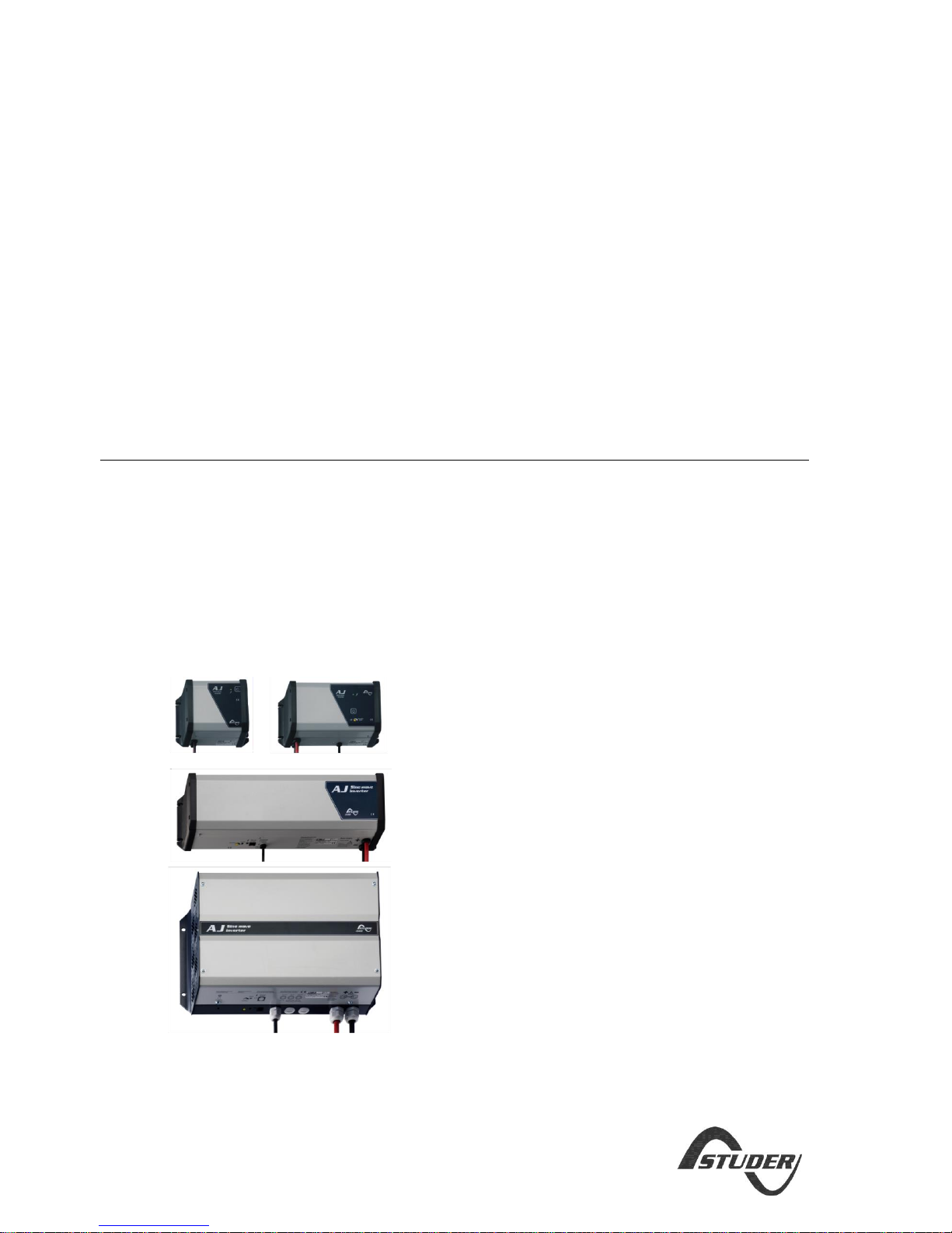
AJ 275-12
AJ 350-24
AJ 400-48
AJ 500-12
AJ 600-24
AJ 700-48
AJ 1000-12
AJ 1300-24
AJ 2100-12
AJ 2400-24

STUDER Innotec SA AJ
V3.04 2
ENGLISH DESCRIPTION ................................................................................................................................................ 5
INTRODUCTION ....................................................................................................................................................................... 5
WARNING .............................................................................................................................................................................. 5
INSTALLATION ......................................................................................................................................................................... 5
Mounting the inverter ............................................................................................................................................... 5
CONNECTION .......................................................................................................................................................................... 6
CONNECTING THE CONSUMER DEVICES ........................................................................................................................................ 6
Note ........................................................................................................................................................................... 6
EQUIVALENT DIAGRAM ............................................................................................................................................................. 6
CONNECTING THE BATTERY ........................................................................................................................................................ 6
USE ...................................................................................................................................................................................... 7
CONTROL AND INDICATORS ....................................................................................................................................................... 7
ACOUSTIC INDICATOR ............................................................................................................................................................... 7
ALARM BY VOLTAGE FLICKERING ................................................................................................................................................. 7
MODEL WITH STAND-BY SYSTEM ................................................................................................................................................ 8
ACTIVATION / DEACTIVATION OF FUNCTIONS: ............................................................................................................................... 9
SAFETY .................................................................................................................................................................................. 9
BATTERY LIFETIME OPTIMIZER – BLO ....................................................................................................................................... 10
WARRANTY LIMIT .................................................................................................................................................................. 12
LIMITS OF MANUFACTURER LIABILITY ......................................................................................................................................... 12
JT8 REMOTE CONTROL FOR AJ 1000-12 TO 2400-24 ................................................................................................................ 12
MODELS WITH BUILT-IN SOLAR CHARGER (OPTION – S) ................................................................................................................. 13
CONNECTION OF THE MODULES AJ 2100/2400-S ...................................................................................................................... 13
TECHNICAL DATA ................................................................................................................................................................... 14
DEUTSCHE BESCHREIBUNG ....................................................................................................................................... 16
EINFÜHRUNG........................................................................................................................................................................ 16
VORSICHT ............................................................................................................................................................................ 16
INSTALLATION ....................................................................................................................................................................... 16
Montageort des AJ ................................................................................................................................................... 16
Befestigung des AJ ................................................................................................................................................... 16
ANSCHLUSS .......................................................................................................................................................................... 17
ANSCHLUSS DER VERBRAUCHER ............................................................................................................................................... 17
Bemerkung............................................................................................................................................................... 17
PRINZIPSCHEMA .................................................................................................................................................................... 17
ANSCHLUSS DER BATTERIE ...................................................................................................................................................... 17
ANWENDUNGEN ................................................................................................................................................................... 18
BEDIENUNG UND ANZEIGEN .................................................................................................................................................... 18
AKUSTISCHER SIGNALGEBER .................................................................................................................................................... 18
ALARM DURCH SPANNUNGSSCHWANKUNG ................................................................................................................................... 19
LASTERKENNUNGSSCHALTUNG „STAND-BY“ .................................................................................................................................. 19
AKTIVIERUNG / DEAKTIVIERUNG VON FUNKTIONEN ...................................................................................................................... 20
SICHERHEITEN ....................................................................................................................................................................... 20
SCHUTZ DER BATTERIE DURCH ABSCHALTEN BEI UNTERSPANNUNG: ................................................................................................ 20
BATTERIELEBENSDAUER-OPTIMIERER (BATTERY LIFETIME OPTIMIZER –BLO): ................................................................................... 21
UNTERHALT.......................................................................................................................................................................... 22
GARANTIEAUSSCHLUSS ........................................................................................................................................................... 23
HAFTUNGSAUSSCHLUSS .......................................................................................................................................................... 23

STUDER Innotec SA AJ
V3.04 3
JT8 FERNSTEUERUNG FÜR AJ 1000-2400 ................................................................................................................................ 23
MODELLE MIT SOLARLADEREGLER (OPTION – S) ......................................................................................................................... 24
ANSCHLUSS DES SOLARMODULE AN AJ 2100/2400-S : ............................................................................................................... 24
BEISPIEL .............................................................................................................................................................................. 24
TECHNISCHE DATEN ............................................................................................................................................................... 25
INSTRUCTIONS EN FRANÇAIS .................................................................................................................................... 27
INTRODUCTION ..................................................................................................................................................................... 27
MISE EN GARDE .................................................................................................................................................................... 27
INSTALLATION ....................................................................................................................................................................... 27
Lieu de montage de l’onduleur ................................................................................................................................ 27
Fixation de l’onduleur .............................................................................................................................................. 27
RACCORDEMENT ................................................................................................................................................................... 28
RACCORDEMENT DES CONSOMMATEURS .................................................................................................................................... 28
SCHEMA EQUIVALENT ............................................................................................................................................................. 28
RACCORDEMENT DE LA BATTERIE .............................................................................................................................................. 28
UTILISATION ......................................................................................................................................................................... 29
COMMANDE ET INDICATEURS ................................................................................................................................................... 29
INDICATEUR SONORE .............................................................................................................................................................. 29
ALARME PAR FLUCTUATION DE TENSION ..................................................................................................................................... 29
MODELES AVEC STAND-BY ....................................................................................................................................................... 30
ACTIVATION / DESACTIVATION DE FONCTIONS: ............................................................................................................................ 31
SECURITES ........................................................................................................................................................................... 31
PROTECTION DE LA BATTERIE PAR DECONNEXION EN TENSION BASSE : .............................................................................................. 31
OPTIMISEUR DE DUREE DE VIE DE BATTERIE (BATTERY LIFETIME OPTIMIZER – B.L.O.) :....................................................................... 32
MAINTENANCE ..................................................................................................................................................................... 33
EXCLUSION DE LA GARANTIE .................................................................................................................................................... 34
EXCLUSION DE LA RESPONSABILITE ............................................................................................................................................ 34
JT8 - COMMANDE A DISTANCE POUR AJ 1000 A 2400 ................................................................................................................ 34
MODELES AVEC CHARGEUR SOLAIRE (OPTION – S) ....................................................................................................................... 35
RACCORDEMENT DES MODULES SUR AJ 2100/2400-S : .............................................................................................................. 35
EXEMPLES DE MONTAGE ......................................................................................................................................................... 35
DONNEES TECHNIQUES ........................................................................................................................................................... 36
INSTRUCCIONES EN ESPAÑOL ................................................................................................................................... 38
INTRODUCCIÓN ..................................................................................................................................................................... 38
ATENCIÓN............................................................................................................................................................................ 38
INSTALACIÓN ........................................................................................................................................................................ 38
Lugar de montaje del inversor ................................................................................................................................. 38
Fijación del inversor ................................................................................................................................................. 38
CONEXIÓN ........................................................................................................................................................................... 39
CONEXIÓN DE LOS CONSUMIDORES ........................................................................................................................................... 39
ESQUEMA DE PRINCIPIO .......................................................................................................................................................... 39
CONEXIÓN DE LA BATERÍA ....................................................................................................................................................... 39
UTILIZACIÓN ......................................................................................................................................................................... 40
FUNCIONES E INDICADORES ..................................................................................................................................................... 40
INDICADOR ACÚSTICO ............................................................................................................................................................. 40
ALARMA POR FLUCTUACIÓN DE TENSIÓN .................................................................................................................................... 41
MODELOS CON STANDBY ........................................................................................................................................................ 41

STUDER Innotec SA AJ
V3.04 4
ACTIVACIÓN / DESACTIVACIÓN DE FUNCIONES ............................................................................................................................. 42
SEGURIDAD .......................................................................................................................................................................... 42
OPTIMIZADOR DE VIDA ÚTIL DE BATERÍA (BATTERY LIFETIME OPTIMIZER – B.L.O.): ........................................................................... 43
MANTENIMIENTO .................................................................................................................................................................. 44
LÍMITES DE GARANTÍA............................................................................................................................................................. 45
EXCLUSIÓN DE RESPONSABILIDAD ............................................................................................................................................. 45
JT8 – CONTROL REMOTO PARA AJ 1000 A 2400 ....................................................................................................................... 45
MODELOS CON CARGADOR SOLAR (OPCIÓN – S) .......................................................................................................................... 46
CONEXIÓN DE LOS MÓDULOS SOBRE AJ 2100/2400-S: ............................................................................................................... 46
EJEMPLOS DE MONTAJE .......................................................................................................................................................... 46
DATOS TECNICOS ................................................................................................................................................................... 47
DECLARATION OF EC CONFORMITY ........................................................................................................................................... 49
STUDER Innotec SA AJ
V3.04 5
ENGLISH DESCRIPTION
INTRODUCTION
The AJ series sine wave inverters have been
designed to meet industrial and domestic
needs. They meet the highest requirements in
terms of comfort, safety and reliability.
Any device designed for the public electrical
grid of 230 V 50 Hz can be connected to them
(up to the nominal power of the inverter).
The AJ series is the perfect source of voltage in
any place where the public grid is not
available.
This document is an essential part of the inverter
and must always be carried with it and be
available for anyone working on the
installation.
Should you have any doubt or question, do not
hesitate to contact your specialist salesperson
who will give you the best advice.
WARNING
A deficient assembly could result in damage to
the device, cause function failures or potential
damage to the users.
The working device generates a high voltage
which might be lethal in case of contact. So,
any manipulation of the inverter must be
carried out with utmost care and meet the
local rules.
THE OWNER MUST NOT MANIPULATE ANY PIECE
INSIDE THE INVERTER.
Opening the inverter or using it incorrectly will
result in the immediate loss of the warranty.
The inverter AJ is to be used only with a lead
battery. As for the use of batteries, follow the
manufacturer’s instructions.
No current or voltage generating device
(public grid, generator, ...) may be connected
to the output of the inverter because this could
result into its destruction.
INSTALLATION
The AJ sine wave inverter is an electronic
device, for which some caution must be taken
when installing it:
Place where the inverter is to be installed:
Out of reach for unauthorized persons,
especially children.
In a dry place (max. 95% humidity), and in any
case with no condensation.
Not directly on top of the batteries.
No easily inflammable material should be
placed directly underneath or close to the AJ.
Ventilation must be free, and a space of 10 cm.
on each side is needed for good evacuation of
the internal heat.
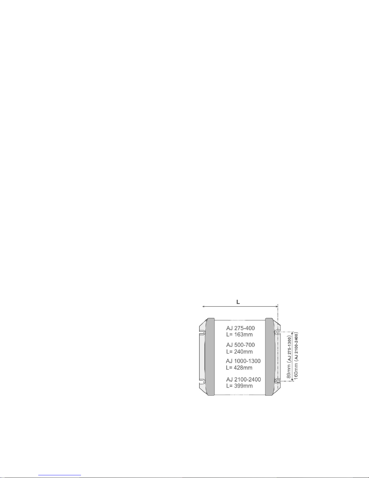
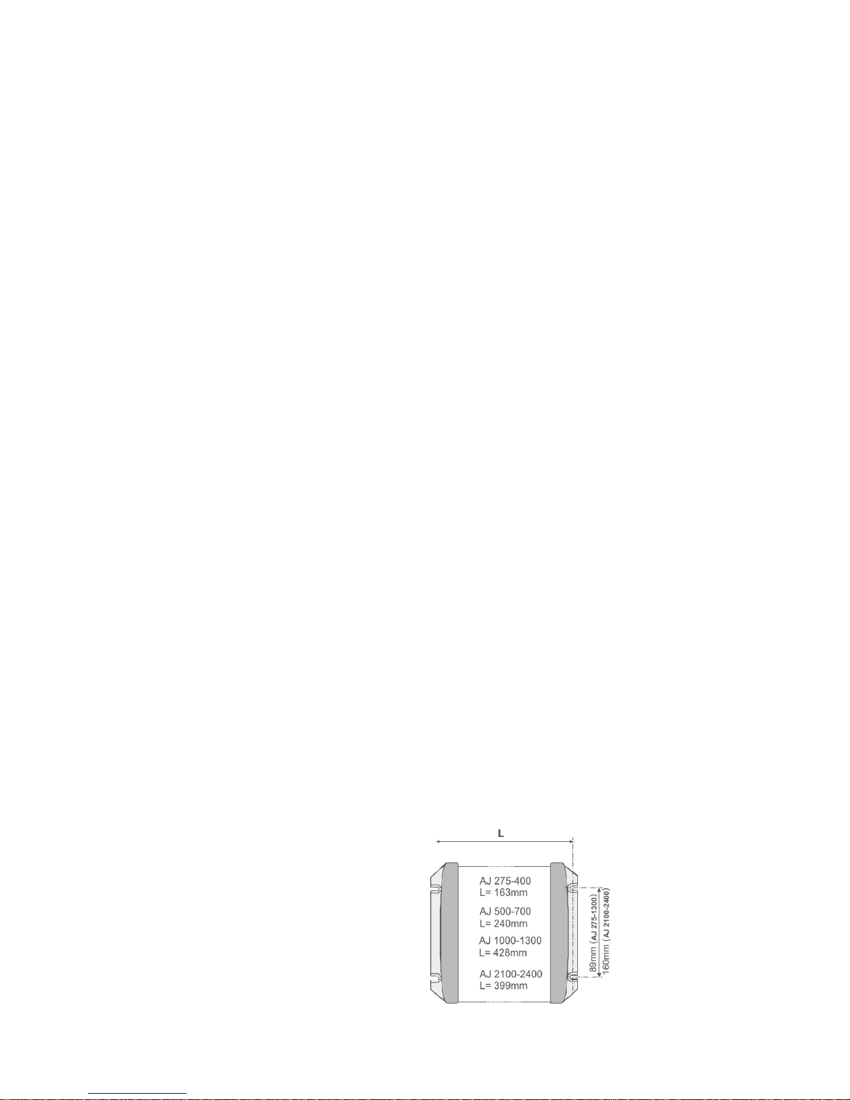
Mounting the inverter
The inverter shall be mounted on a
nonflammable surface by screws (diameter
max. 4 mm for AJ 275-AJ 1300 or max. 8 mm for
AJ 2100 and 2400) using the four holes
provided. The fixing screws are not supplied
with the inverter. It may be fixed in any position.
STUDER Innotec SA AJ
V3.04 6
CONNECTION
The connection of the inverter should be done
with utmost care for a good operation of the
system. The technical data and connection’s
description are either under one side of the
inverter or onto the cable connection side. First
connect the consumer devices and install a
plug so as to prevent any further contact once
the 230 V voltage is present.
Installation is to be made only by authorized
persons.
CONNECTING THE CONSUMER DEVICES
The AJ is supplied with a 230 V cable to be
connected to the consumer devices. This
connection must be done observing the
following colours:
Yellow-green: earth
Brown: phase
Blue: neutral
Once the consumer devices are connected,
make sure that they are turned off before
connecting the battery.
Note
An Inverter constitutes a voltage source
independent from the grid and could be
considered in the same way as a generator set.
The voltage in between the phase and the
neutral is 230V. An appropriate divisor
establishes a 115V voltage in between neutral
and earth, and between the phase and earth.
According to the local prescriptions or
particular requirement, (example: use of a
ground fault detector) a true neutral may be
established by connecting the neutral and the
earth wire together (yellow - green and blue).
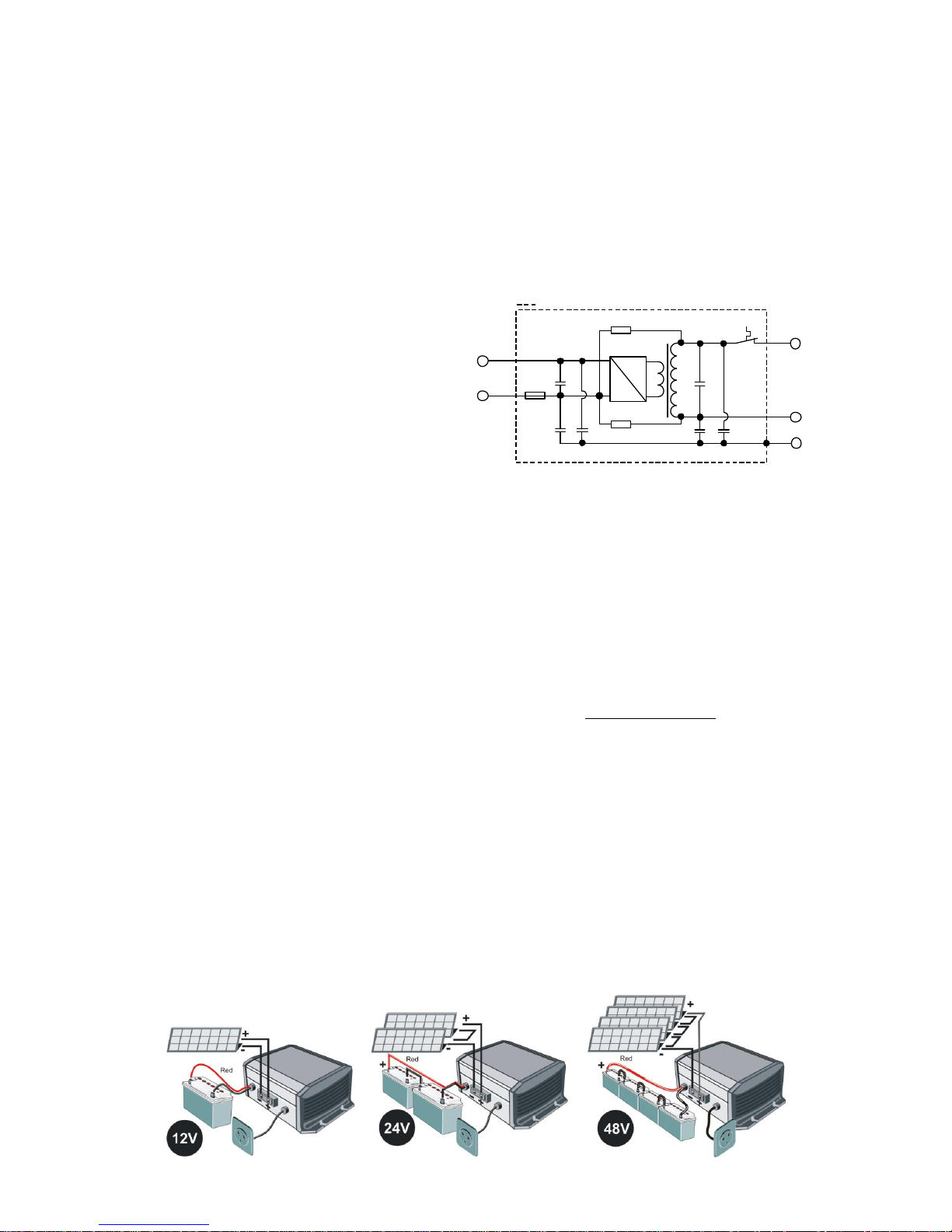
EQUIVALENT DIAGRAM
CONNECTING THE BATTERY
Once the consumer devices are connected,
make sure that the installations instructions of
the 230V has been followed with utmost care
before connecting the battery.
The battery cables are supplied with the
inverter and already connected in it.
Connect the battery observing carefully the
polarity.
The AJ inverter, except AJ 2100-12, is protected
against reverse polarity by a fuse, but should
the polarity be reversed, the inverter must be
sent to the manufacturer for control.
Connect the battery using the following
colours:
BLACK cable: negative pole (-)
RED cable: positive pole (+)
For AJ 275-12 (-S) to 700-48 (-S), a bicoloured
cable is used. Go for the dominant colour.
When connecting the battery, there is a spark
(Danger of explosion!), because of the
charging of the internal filtering capacitors.
A fire security fuse must be installed on the
battery.
DC/AC
R1
R2
1uF/63V 10nF/275V
3x
Inom
+
-
R1=R2 >2,7M ohm (not existing in AJ 275 -AJ 350 et AJ 400
Metallic part of the enclosure
Blue
Green/
Yelow
Brown
Fuse
Red
Black

STUDER Innotec SA AJ
V3.04 7
Check that the cables are well adjusted and
well tightened.
As long as it is possible, do not extend the
cables supplied with the batteries. Extending
them may increase the losses and lead to a
malfunction of the inverter.
Once the inverter is connected to the batteries,
a 230 V voltage is present at the output of the
inverter.
USE
CONTROL AND INDICATORS
Control switch on/off
There is a switch on the inverter to activate or
deactivate it. Use this function to save the
energy of the batteries when you are not using
the inverter.
Note:
The solar charge controller remains in operation
even when the inverter is off.
“Functioning” indicator
(green LED 1)
A green light on the inverter indicates its
functioning mode:
Illuminated: A 230 V voltage is present at
the output, the inverter is on.
Blinking:
_ _ _ _ _ No load (stand-by).
__ __ __ __ __ The 230 V voltage has been
cut due to an alarm; the
inverter will automatically
resume function when the
failure has disappeared (see
the failure table p. 10).
Off : The 230 V voltage is NOT
present at the output, the
inverter is off.
B.L.O. indicator (green LED 2)
Led only on AJ 275-12 to 700-48
This indicator is illuminated only if the enhanced
Battery Lifetime Optimizer function (description
p. 10) is activated.
Activation/Deactivation described in p. 9.
ACOUSTIC INDICATOR
The AJ inverter has an acoustic indicator for the
following cases:
Intermittent beeps:
There is a failure in the inverter and the output
voltage will be interrupted.
Overheat:
The acoustic indicator beeps 3ºC before
cutting the voltage. Reduce the consumption
in order to lower the inverter temperature and
to avoid the output voltage is cut off.
Low battery voltage:
The indicator beeps during a minute before
the interruption. Reduce the consumption in
order to get the battery voltage rise and to
avoid that the output voltage is cut off.
Continuous beep for two seconds:
You have pushed the ON/OFF switch to restart
the inverter. The output voltage will be
immediately present after the acoustic signal.
The acoustic warnings can be deactivated as
per the procedure described p. 9.
ALARM BY VOLTAGE FLICKERING
When the acoustic indicator is deactivated or
when the inverter is out of hearing, it can be
useful to be warned of an imminent inverter
stop due to an “overheat” or a “battery under
voltage”. If this function is activated (see p. 9
for Activation/Deactivation of functions), the
output voltage will flicker slightly (max. 20%),
leading to a variation of the lights intensity and
therefore indicating the imminent stop of
energy supply.
The user can then choose to reduce his
consumption in order to secure the supply to
priority loads (for instance lighting).

STUDER Innotec SA AJ
V3.04 8
MODEL WITH STAND-BY SYSTEM
The inverters from the AJ 500-12 are equipped
with a stand-by system (also available in the
models AJ 275-12/350-24/400-48 with the
option -S).
The stand-by is an energy saving system which
turns off the inverter intermittently when no
consumer is detected. In this mode the
functioning indicator (green LED 1) blinks,
showing the intermittent presence of the
voltage.
The detection threshold is set by default at 2 W.
On models from AJ 500-12 onwards it is possible
to deactivate this function or to modify the
threshold by adjusting the yellow Turning Knob
marked Stand-by.
Adjusting the switching-on level is as follows:
Switch off all consuming devices; turn the
Turning Knob to the right (clockwise) until the
LED is blinking, switch ON the smallest
consuming device (i.e. mobile phone charger);
turn the Turning Knob slowly to the left until LED
is lit continuously. Check that the inverter goes
back in stand-by mode when you remove the
load. If not, this means that the load is too small
to be detected.
If the stand-by is not required, turn the Knob fully
to the right.
The minimal load detected can be adjusted
between 1 and 20 W. In most cases this
adjustment is not necessary. This adjustment is
made with a small screw driver in the hole
marked stand-by. In the full counter clockwise
position, the sensibility is minimal (20 W). Do not
push on the screw driver.
NOTE: In this mode the output voltage is
intermittently present at the output!

STUDER Innotec SA AJ
V3.04 9
ACTIVATION / DEACTIVATION OF FUNCTIONS:
The following functions of the AJ range can be freely enabled or disabled by the user:
1. Acoustic warning of imminent stop of the inverter according to p. 7.
2. Battery lifetime optimizer function as described p. 10.
3. Imminent stop alarm by voltage flickering as described p. 7.
The state « activated » or « deactivated » of the functions is indicated by the buzzer with a continuous
push on the on/off key after a duration given for each function as per the table below:
Single « beep » short = function activated
Double « beep » short = function deactivated
Function
Duration of impulse
(onto on/off)
Default setting
1.
Acoustic alarm
5 seconds
Activated
2.
Battery Lifetime Optimization
(B.L.O.)
10 seconds
Deactivated
3.
Alarm by voltage flickering
15 seconds
Deactivated
The state is reversed if the on/off key is released within 2 seconds following the buzzer sound.
To consult the state of functions without having any effect on them or changing their programming
it is possible to maintain the on/off key pushed on. Beyond 20 seconds the buzzer will sound
continuously to indicate the end of the sequence and will stop by the release of the key.
SAFETY
The inverter is electronically protected. It is protected against reverse polarity by an internal fuse,
except for AJ 2100-12 inverter, which must be protected by an external fuse. The next table displays
the various possible default cases and their consequences.
Caution: the inverter is not protected against the connection of an AC source (generator or grid) at
its output. Such connection will cause a major failure and should be avoided.
Battery protection by LVD - Low voltage disconnection battery protection:
The battery is protected from deep discharge by stopping the inverter if the battery reaches a
voltage lower than 0.87*Unom (10.5, 21 or 42 V) during more than 1 minute. An acoustic signal or a
voltage flickering (if authorized) is activated during 1 minute before the inverters stops. The inverter
must then be restarted manually. It will restart automatically if the battery voltage is back to a value
higher than 1.04*Unom (12.5, 25 or 50 V).The inverter will stop immediately (with no delay) if the
battery voltage is lower than 0.75*Unom (9, 18 or 36 V).
STUDER Innotec SA AJ
V3.04 10
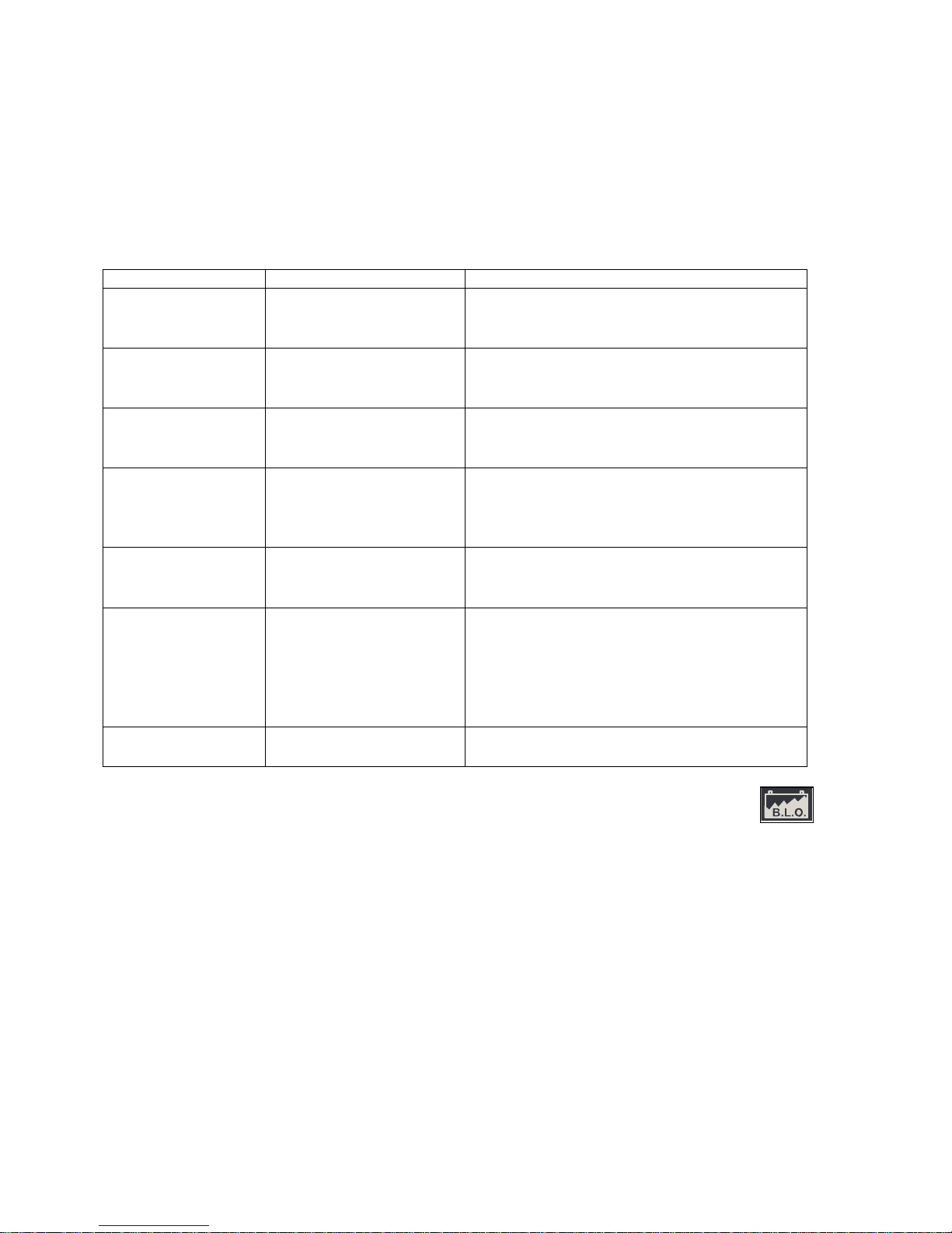
The table below will show you the different causes of inverter stopping.
BATTERY LIFETIME OPTIMIZER – BLO
Cycling a battery in permanent charging
mode from 0 to 30% is often a cause of early
aging of batteries, particularly in solar home
systems.
In order to enhance the battery lifetime, the AJ
inverters are equipped with a unique function
that will readjust the low voltage disconnection
(LVD) threshold according to the behavior of
the user consumption. This allows a full
recharge of the battery.
This function can be activated at any time as
per the procedure described p. 9.
An indicator (green LED 2) only available on
from AJ 275-12 to 700-48 is lit or blinks when this
function is activated. The number of blinks
indicates the LVD currently applied.
If this indicator is lit continuously, this means that
the use of the battery is correct and that it was
well charged. The LVD is then set at 0.87*unom
(10.5, 21or 42V) as per the model. This also
means that you have the widest availability of
the energy stored and that your battery is likely
to last longer.
If the indicator is blinking one or several times,
this means that the use of the battery is
restricted and that the disconnection voltage
was set according to the table below (+/- 2%).
CAUSE
CONSEQUENCE
SOLUTION
Low battery
voltage, Voltage <
0.87*Unom
Inverter temporary
stopped, the green
indicator blinks.
Automatic restart when the battery
voltage rises at 1.04*Unom.
Deep discharged
battery 0.75*Unom
Inverter stopped
Inverter should be manually restarted
when the battery has reached
=0.87*Unom
Overheating
Inverter temporary
stopped, the green
indicator blinks.
Automatic restart when the temperature
reaches the normal range.
Battery
overvoltage
1.33*Unom
Inverter stopped.
Wait until the battery voltage reaches the
correct level.
Push the ON/OFF button to reactivate the
inverter. 1.25*Unom
Short circuit at the
output
Inverter stopped.
Eliminate the short circuit.
Push the ON/OFF button to reactivate the
inverter.
Overload
Inverter stopped.
Use the inverter only in the range of its
nominal power. Regular use in overload
power diminishes the lifetime of the
inverter.
Push the ON/OFF button to reactivate the
inverter.
Battery reverse
polarity
Internal fuse broken
down.
Back to manufacturer for testing.

STUDER Innotec SA AJ
V3.04 11
This strategy will of course restrict the use of the
battery and drive the user to reduce his
consumption or to increase the production (by
an additional charger connected to a backup
generator for instance).
When the battery voltage is higher than
1.08*Unom (13 V, 16 V, 52 V) during 2 hours, the
LVD is progressively stepped down by a
decrement of 33 mV/cell (0.4 V @ 12 V). This
process insures that the average charge of the
battery is sufficient (over 50 %) to assure its
optimized lifetime.
This function is particularly useful in solar home
systems where the battery is sized in 3-5 times
the daily average production. For instance a
200 W solar system producing 800 Wh/day
connected to a 200-300 Ah / 12 V battery.
If the battery is sized so as to be fully discharged
and charged every day, it may be possible that
the restriction of use implied by the permanent
increase of LVD is not wished. We recommend
then to deactivate the Battery Lifetime
Optimizer.
Maintenance
The inverters of the AJ series do not need any
special maintenance. The casing may be
cleaned with a damp cloth (not wet).
In the case of malfunction or mechanical
deformation, the inverter should be sent back
to the manufacturer for control carefully
packed in its original packing.
Before deciding to send back the inverter,
check the following points:
The battery is loaded and is in
accordance to the nominal input
voltage of the inverter.
The consumer devices do not have any
defect or overload for the inverter (to
make sure, disconnect them).
Should you contact your salesperson, note the
following points before calling:
(You will find this information on the label
underneath the inverter or at the cable side)
Exact model
Serial number
Power of the inverter
Nominal input voltage of the inverter
In case the inverter should not be sent back in
its original packaging, it should be packed in a
stiff carton box and be well protected on all
sides by means of an anti-shock and isolating
layer of min. 5 cm thickness. A weak protection
may cause damages to the inverter during
transport and are not covered by the warranty.
12V
24V
48V
LED
Comments
10.5
21
42
0 x
(ON
)
This is also the
LVD level when
BLO is
deactivated
11V
22V
44
1 x
off
-
11.4
22.8
45.6
2 x
off
Level at BLO
activation
11.6
23.2
46.4
3 x
off
-
11.8
23.6
47.2
4 x
off
-
12
24
48
5 x
off
-
12.2
24.4
48.8
6 x
off
-

STUDER Innotec SA AJ
V3.04 12
WARRANTY LIMIT
The warranty period is 5 years.
It does not cover damages arising from a use
not conforming to the user manual, not
described in it or resulting from any other
inappropriate use like:
Battery reverse polarity
Inadequate input voltage
(overvoltage)
Back-feeding at the inverter output by
public grid, generator or any other
source.
Mechanical shock or deformation
especially by transport due to an
inadequate package.
Contact with liquid or oxidation by
condensation.
Use in inappropriate environment (dust,
corrosive vapour, humidity, high temperature
...).
LIMITS OF MANUFACTURER LIABILITY
Studer Innotec SA cannot control the
installation, use and maintenance of the
inverter. Thus, we are not responsible for
damages, costs or losses resulting from an
installation which is not in accordance with the
regulations or from inappropriate use or
maintenance.
The customer is always responsible for the use
of the Studer inverters.
This device has not been designed and is not
warranted for use in life support equipment or
any other critical device with potential risks of
important harm to people or to the
environment. We do not accept any
responsibility for any violation of patent rights or
other third person rights resulting from the use of
the inverter.
Studer Innotec SA keeps the right to modify its
products without previous notice.
JT8 REMOTE CONTROL FOR AJ 1000-12 TO 2400-24
Functions on remote control are the same as control and indicator on
the inverter (see chapter Use p. 7).
Remote control must be connected to the inverter with the original
Studer 10 m cable or any RJ11/6p 1:1 cable up to 50 m.
STUDER Innotec SA AJ
V3.04 13
MODELS WITH BUILT-IN SOLAR CHARGER
(OPTION – S)
The solar charge controller built in option in the
inverter AJ is meant for charging a battery
exclusively from a solar generator.
Any other source of current needs an external
and suitable charge controller.
The maximum (open) voltage of the solar
generator is 23 V for 12 V systems, 46 V for 24 V
systems and 90 V for 48 V systems.
Connect firstly the inverter to the battery before
connecting the solar generator. The
adjustment mode is an I/Uuo (“floating”) shunt
and it guarantees optimal charge conditions
along the battery lifetime.
The yellow indicator displays the functioning
mode:
Illuminated: The solar charge is at its
maximum.
Not illuminated: the solar generator is not
connected or the battery is
fully charged, or the solar
generator does not get solar
irradiation.
Blinking: The battery is more than 95%
charged and the charger is in
“floating” mode to complete
the charge. The blinking
frequency varies as per the
capacity of the battery and
the power of the solar
generator.
NOTE: Since the solar charge controller
integrated in the AJ is of PWM type, it is
necessary to use 36 or 72 cell PV modules
(12V or 24V respectively). All other types of
PV modules require an MPPT charge
controller (i.e VarioTrack or VarioString).
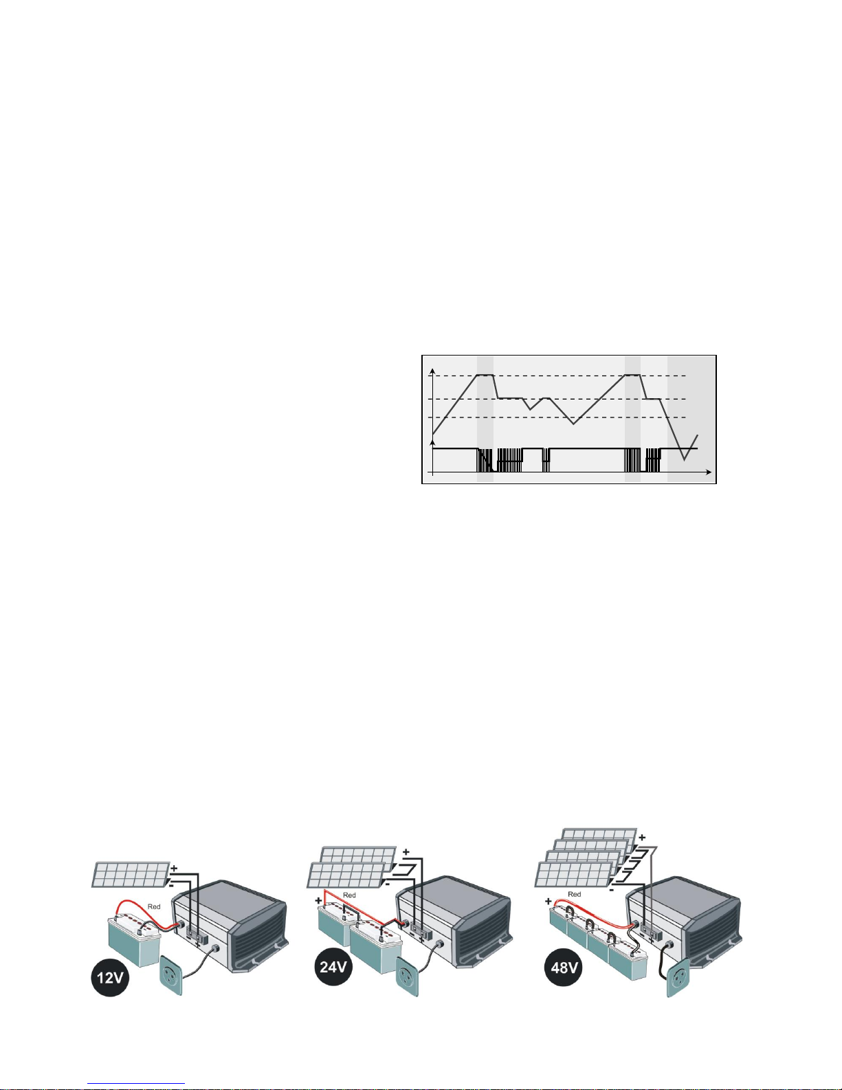
CONNECTION OF THE MODULES AJ 2100/2400-S
On AJ 2100-S/2400-S inverters, a preinstalled cable (2 x 6mm2) replaces the terminals.
Wiring should be done through a connecting box.
Positive (+) pole to the brown or red cable
Negative (-) pole to the blue or black cable
Examples
14,4V/28,8V/57,6V
13V/26V/52V
13,5V/27V/44V
Ubatt
I pv
I
U
2h 2h
STUDER Innotec SA AJ
V3.04 14
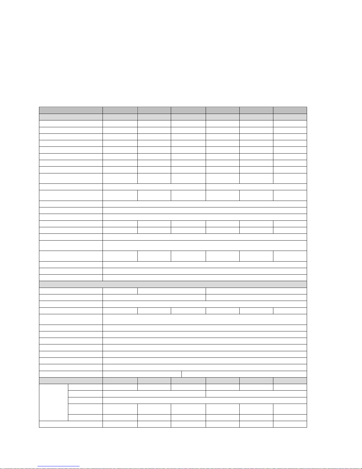
TECHNICAL DATA
Model
AJ 275-12
AJ 350-24
AJ400-48
AJ 500-12
AJ 600-24
AJ 700-48
Inverter
Nominal battery voltage
12Vdc
24Vdc
48Vdc
12Vdc
24Vdc
48Vdc
Input voltage range
10.5 – 16Vdc
21 – 32Vdc
42 – 64Vdc
10.5 – 16Vdc
21 – 32Vdc
42 – 64Vdc
Continous power at 25ºC
200VA
300VA
300VA
400VA
500VA
500VA
Power 30 min. at 25ºC
275VA
350VA
400VA
500VA
600VA
700VA
Power 5 min. at 25ºC
350VA
500VA
600VA
575VA
675VA
900VA
Power 5 sec.at 25ºC
450VA
650VA
1000VA
1000VA
1200VA
1400VA
Maximum asymmetric load
150VA
150VA
200VA
250VA
300VA
300VA
Max. efficiency (%)
93%
94%
94%
93%
94%
94%
Cos φ max.
0.1 – 1 up to
200VA
0.1 – 1 up to
300VA
0.1 – 1 up to
300VA
0.1 – 1 up to
400VA
0.1 – 1 up to
500VA
0.1 – 1 up to
500VA
Detection of the load
2W (only with the solar option –S)
Adjustable: 1 20W
Current of chort-circuit 2 sec. (exit)
2.3Aac (4.6Aac*)
3.2Aac
(6.4Aac*)
4.6Aac (9.2Aac*)
5.2Aac (10Aac*)
5.7Aac
(11.4Aac*)
7Aac (14Aac*)
Output voltage
Sine wave 230Vac (120Vac*) ±5%
Frequency
50Hz (60Hz*) ±0.05% (crystal controlled)
Distortion THD (resistive load)
< 5% (at Pnom. & Uin nom.)
Consumption Stand-by
0.3W**
0.5W**
1.1W**
0.4W
0.6W
1.5W
Consumption „ON“ no load
2.4W
3.5W
5.2W
4.6W
7.2W
12W
Overheat protection (±5ºC)
Shut down at 75ºC, Auto-restart at 70ºC
Overload and short circuit
protection
Automatic disconnection with 2 restart attempts
Reverse polarity protection by
internal fuse
60A
40A
25A
120A
90A
60A
Deep discharge battery protection
Shut off at 0.87 x Unom, Automatic restart at Unom.
Max. battery voltage
Shut off at >1.33 x Unom, Automatic restart at < Umax
Acoustic alarm
Before low battery or overheating disconnection
General data
Weight
2.4 kg
2.6 kg
4.5 kg
Dimensions hxwxl (mm)
142x163x84
142x240x84
Protection index IP
IP 30 conforms to DIN 40050
Certification ECE-R 10 (E24)
●
●
Not available
●
●
Not available
EC confirmity
Low Voltage Directive (LVD) 2014/35/EU - EN 50178:1997 - EN 62109-1:2010
Electromagnetic Compliance (EMC) Directive 2014/30/EU - EN 61000-6-2:2005- EN 61000-6-4:2007/A1:2011
Operating temperature
-20ºC up to +50ºC
Relative humidity in operation
95% without condensation
Ventilation forced
From 45ºC ±5ºC
Acoustic level
< 45 dB (with ventilation)
Warranty
5 years
Approximate correction of Pnom
-1.5%/ºC as from +25ºC
Recommended battery capacity
> 5 x Pnom/Unom (recommended value in Ah)
Length cables (Battery/left AC)
1.2m /1m
1.5m / 1m
Options
AJ 275-12
AJ 350-24
AJ400-48
AJ 500-12
AJ 600-24
AJ 700-48
Solar
regulator
(PWM)
Voltage max
25Vdc
45Vdc
90Vdc
25 Vdc
45Vdc
90Vdc
Current max.
10Adc
15Adc
Principle
3 floating stages (I/U/UO)
Absorption
voltage
14.4Vdc
28.8Vdc
57.6Vdc
14.4Vdc
28.8Vdc
57.6Vdc
Floating voltage
13.6Vdc
27.2Vdc
54.4Vdc
13.6Vdc
27.2Vdc
54.4Vdc
Plug for remote control (RCM)
● ● ● ● ●
●
STUDER Innotec SA AJ
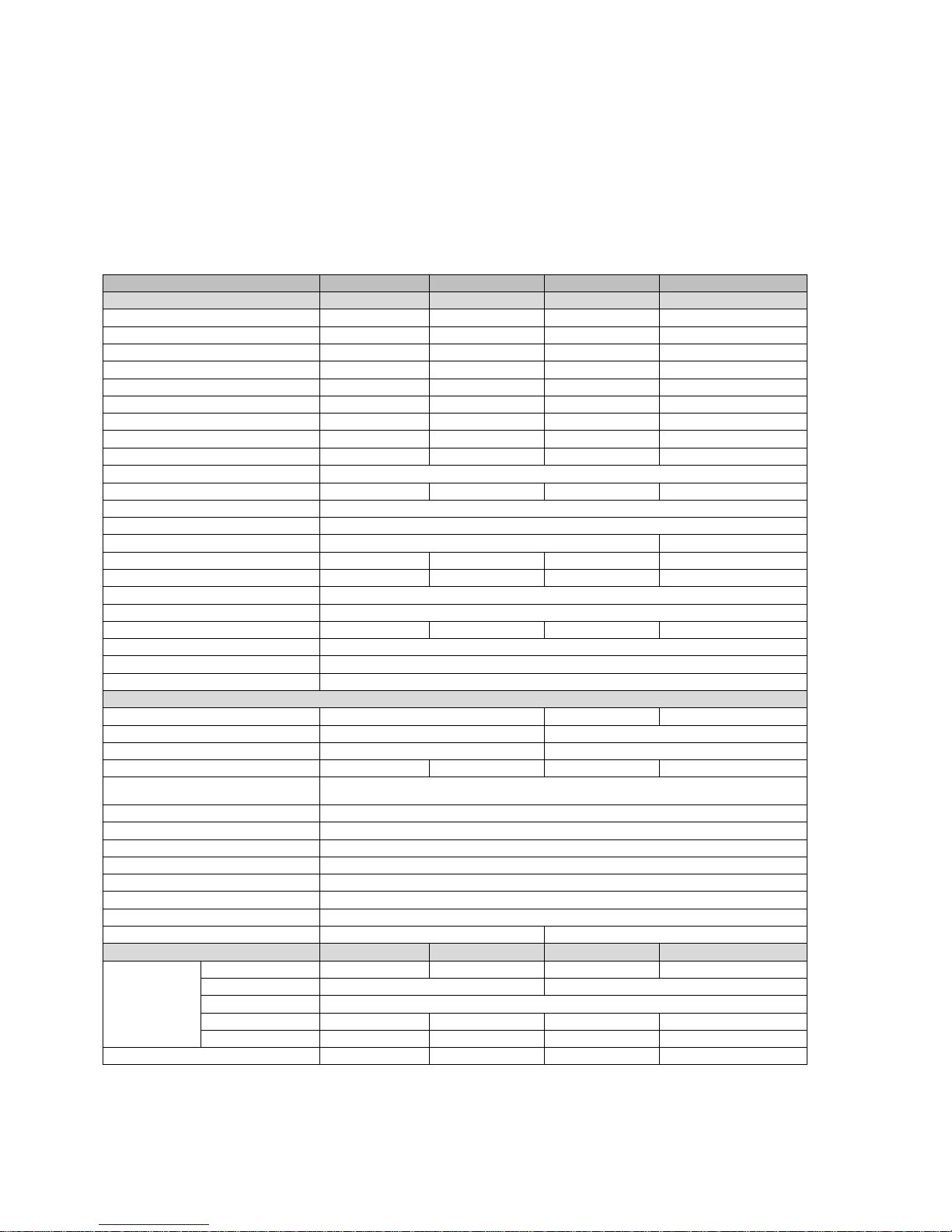
V3.04 15
Model
AJ 1000-12
AJ 1300-24
AJ2100-12
AJ 2400-24
Inverter
Nominal battery voltage
12Vdc
24Vdc
12Vdc
24Vdc
Input voltage range
10.5 – 16Vdc
21 – 32Vdc
10.5 – 16Vdc
21 – 32Vdc
Continous power at 25ºC
800VA
1000VA
2000VA
2000VA
Power 30 min. at 25ºC
1000VA
1300VA
2100VA
2400VA
Power 5 min.at 25ºC
1200VA
2000VA
2450VA
2800VA
Power 5 sec. at 25ºC
2200VA
2800VA
5000VA
5200VA
Maximum asymmetric load
500VA
600VA
1000VA
1200VA
Max. efficiency (%)
93%
94%
92%
94%
Cos φ max.
0.1 – 1 up to 800VA
0.1 – 1 up to 1000VA
0.1 – 1 up to 2000VA
0.1 – 1 up to 2000VA
Detection of the load
Adjustable: 1 20W
Current of chort-circuit 2 sec. (exit)
10Aac (20Aac*)
13Aac (26Aac*)
26Aac (52Aac*)
30Aac (60Aac*)
Output voltage
Sine wave 230Vac (120Vac*) ±5%
Frequency
50Hz (60Hz*) ±0.05% (crystal controlled)
Distortion THD (resistive load)
< 5% (at Pnom. & Uin nom.)
< 3% (at Pnom. & Uin nom.)
Consumption Stand-by
0.7W
1.2W
0.7W
1.2W
Consumption „ON“ no load
10W
13W
16W
16W
Overheat protection (±5ºC)
Shut down at 75ºC, Auto-restart at 70ºC
Short circuit protection
Automatic disconnection with 2 restart attempts
Reverse polarity protection by internal fuse
125A
100A
Not protected
150A
Deep discharge battery protection
Shut off at 0.87 x Unom, Automatic restart at Unom.
Max. battery voltage
Shut off at >1.33 x Unom, Automatic restart at < Umax
Acoustic alarm
Before low battery or overheating disconnection
General data
Weight
8.5 kg
19 kg
18 kg
Dimensions hxwxl (mm)
142x428x84
273x399x117
Protection index IP
IP 30 conforms to DIN 40050
IP 20 conforms to DIN 40050
Certification ECE-R 10 (E24)
● ● ●
●
EC confirmity
Low Voltage Directive (LVD) 2014/35/EU - EN 50178:1997 - EN 62109-1:2010
Electromagnetic Compliance (EMC) Directive 2014/30/EU - EN 61000-6-2:2005- EN 61000-6-4:2007/A1:2011
Operating temperature
-20ºC up to +50ºC
Relative humidity in operation
95% without condensation
Ventilation forced
From 45ºC ±5ºC
Acoustic level
< 45 dB (with ventilation)
Warranty
5 years
Approximate correction of Pnom
-1.5%/ºC as from +25ºC
Recommended battery capacity
> 5 x Pnom/Unom (recommended value in Ah)
Length cables (Battery/left AC)
1.5m /1m
1.7m / 1m
Options
AJ 1000-12
AJ 1300-24
AJ2100-12
AJ 2400-24
Solar regulator
(PWM)
Voltage max
25Vdc
45Vdc
25Vdc
45 Vdc
Current max.
25Adc
30Adc
Principle
3 floating stages (I/U/UO)
Absorption voltage
14.4Vdc
28.8Vdc
14.4Vdc
28.8Vdc
Floating voltage
13.6Vdc
27.2Vdc
13.6Vdc
27.2Vdc
Remote control JT8 supplied with 5 m cable
● ● ●
●
STUDER Innotec SA AJ
V3.04 16
DEUTSCHE BESCHREIBUNG
EINFÜHRUNG
Die Wechselrichter der Serie AJ sind für den
Betrieb von allen handelsüblichen 230V
Geräten konzipiert worden. Die AJ genügen
den höchsten Anforderungen an
Zuverlässigkeit, Sicherheit und Komfort.
Jedes für das 230V-Wechselstromnetz
geeignete Gerät kann auch mit einem AJ
betrieben werden.
Ein AJ ist die ideale Spannungsquelle überall da
wo das öffentliche Netz nicht hinführt.
Diese Beschreibung ist in jedem Fall Teil der
Lieferung eines AJ. Sie muss allen Personen
welche mit einem AJ arbeiten zur Verfügung
stehen!
Bei eventuellen Fragen oder Unklarheiten kann
Ihnen der Händler Auskunft geben.
VORSICHT
Eine falsche Behandlung oder Montage des
Wechselrichters kann schwerwiegende Folgen
haben wie; Beschädigung des Gerätes,
hervorrufen einer Fehlfunktion oder den
Benutzer gefährden!
Der AJ erzeugt eine 230V-Sinusspannung wie im
öffentlichen Stromnetz. Jegliche Berührung
kann fatale Folgen haben! Die
Installationsarbeiten mit dem Wechselrichter AJ
verlangen besondere Aufmerksamkeit und
dürfen nur von geschultem Personal ausgeführt
werden und müssen in jedem Fall den jeweils
gültigen Installationsvorschriften entsprechen.
Der AJ darf in keinem Fall geöffnet werden.
Das Öffnen oder die nicht konforme Anwendung des AJ bedeuten den Verlust
jeglicher Garantieansprüche.
Der AJ darf mit keiner anderen Spannungsoder Stromquelle als mit Bleibatterien betrieben
werden.
Am Ausgang des AJ dürfen keine Spannungsoder Stromquellen wie Notstromgeneratoren,
das öffentliche Netz usw. angeschlossen
werden, da der Wechselrichter zerstört werden
könnte.
Der Einsatz von Batterien verlangt besondere
Vorsicht. Befolgen Sie darum unbedingt die
Richtlinien des Batterieherstellers.
INSTALLATION
Der Sinuswechselrichter AJ ist ein elektronisches
Gerät. Für dessen Installation sind darum einige
Vorsichtsmassnahmen zu beachten.
Montageort des AJ
Der Montageort sollte gegen unbefugten
Zugriff gesichert sein (vor allem auch vor Zugriff
von kleinen Kindern).
In einem trockenen Raum mit einer
Luftfeuchtigkeit von max. 95% ohne
Kondensation.
Nicht direkt über der Batterie.
Bei den Lüftungsein- bzw. Auslässen muss für
eine unbehinderte Lüftung 10cm Freiraum
belassen werden.
In der Umgebung des Wechselrichters darf sich
kein leicht brennbares Material befinden oder
darunter gelagert werden.
Befestigung des AJ
Der Wechselrichter kann, auf einer nicht
brennbaren Unterlage, mit Hilfe von 4
Schrauben (Durchm. max. 4mm für AJ 275-AJ
1300 oder Durchm. max. 8mm für AJ 2100 und
2400) in jeder beliebigen Lage montiert
werden. Für die Befestigung dürfen nur die 4
von aussen zugänglichen Löcher verwendet
werden. Die Befestigungs-Schrauben sind nicht
beigelegt.
 Loading...