


1956
Studebaker
Golden Hawk
Authenticity Guide

1956 Studebaker Golden Hawk
Authenticity Guide
Copyright © 1996, 2017
by Frank J. Ambrogio
For the 1956 Studebaker Golden Hawk Owners Register
Last Update - July 2, 2018
2

Introduction
The original 1956 Studebaker Golden Hawk Authenticity Guide from 1996 was compiled with the
cooperation of members of the 1956 Studebaker Golden Hawk Owners Register. Participating
members responded to questionnaires indicating the color, condition, texture, location, etc., of
items related to authenticity. The results were compiled and compared against other sources to
determine what is probably the most correct condition. Since that time, many new items have
come to light and are included in this new Guide.
Authenticity is a rather nebulous term as applied to Studebakers. During my research, I found
accessories which were not listed in any of the Studebaker literature for 1956 Golden Hawks.
Every effort has been made to research the items listed as thoroughly as possible. I placed more
significance on the Studebaker Chassis, Body, Shop Manuals, as well as magazine articles and
drive reports from the period when the cars were new, than on company brochures and
advertisements which often were printed before the cars actually went into production.
Even relying on magazines from the period was no safe bet. The April 1956 issue of Hot Rod
magazine shows a beautiful picture of the dashboard and steering wheel on page 54. However,
the horn button was from a 1955 model. As for company brochures, the one entitled
STUDEBAKER HAWKS, craftsmanship with a flair also shows a 1956 Golden Hawk dashboard
and steering wheel, however the steering wheel is black, instead of white.
Mine's Original. I have learned to be suspicious of any car described in this way. Decades have
passed, several changes of ownership have most likely occurred, and any number of body shop
visits can do wonders for a car's originality. Even cars that sat for many years probably had some
modification made during their early years. In many cases, the owner wasn’t even aware that a
change was done. One owner’s car had been in the family since new, but the owner wasn’t aware
that the car had a later model Hawk hood. The car had been in two accidents and the hood had
been replaced one time.
Another valuable source of information, although not totally accurate, was the original production
orders. I was able to obtain all 4073 production orders for 1956 Golden Hawks. Even those were
not completely accurate. Several cars were listed with Flight-O-Matic transmission, one showed
a radio from a full size sedan, while many others listed a prototype wheelcover which never saw
production.
There are a few items included here which some might perceive as nitpicking. They are only
presented to raise awareness and to show that there will always be questions, as well as
differences of opinion, when it comes to authenticity. Therefore, this Guide should be used to
provide support for those items which may be questioned. It is not intended as proof that
something on a particular car is or isn’t correct.
Hopefully, this Guide is as accurate and complete as possible, However, this effort is not the final
word. That is why I called it a guide rather than a handbook or manual. In many instances, there
won't be a definitive answer, but rather what appears to be the norm. Some deviations will also
be identified and you can be the judge.
Authenticity questions can sometimes get a little too complex. As an example, the AC-2799 Spoke
Type wheelcovers are a legitimate option for 1956 Golden Hawks. However, they were not
introduced until February of 1956. Would a 1956 Golden Hawk be considered authentic, if it
sported the Spoke Type wheelcovers, and was built before February, 1956?
Although there were no plans to publish revisions or updates to the original Guide, the information
we have uncovered over the past few decades caused me to revisit that philosophy, and offer a
new Guide. Virtually everything pertaining to the 1956 Golden Hawk is stored in the Studebaker
National Museum Archive in South Bend. Unfortunately logistics and finances prevented me from
accessing this data. However one South Bend area owner did some extensive research at the
Last Update - July 2, 2018
Page 3

Introduction
SNM Archive and kindly provided me with copies of that research.
I Hope this Guide will be a source of reference for decades to come and for this reason, I did not
include the names of individuals who provided photos, documentation, or other guidance. I can
only offer my heart felt thanks for their generosity.
This Guide does not get into details as to the color(s) of specific wiring,. The parts and shop
manuals have electrical schematics which often provide this information. If an engineering
drawings indicated such information as, “finish gloss enamel”, I included this type of information.
In this Guide, you will find material concerning the questions which our registered owners have
asked most often. References are made to other Studebaker models including the other 1956
Hawk models. Please see the table below for more information on all the Hawk models.
Hopefully, the information in this Guide will be useful to anyone searching for, maintaining, or
restoring a 1956 Studebaker Golden Hawk.
Frank J. Ambrogio
NOTES:
There were 4073 Serial Numbers assigned to the 1956 Golden Hawk Model year, but only 4071
were produced. Two cars from the South Bend factory were scrapped during production, with no
explanation appearing on the production orders. Not counting the two scrapped cars, the final
totals show 3470 cars produced in South Bend, Indiana, and 601 assembled in Vernon, California.
Original 1956 Golden Hawks were simply not available more than half a century after the last car
was produced. Restored cars, even those done by professionals, did not always follow the exact
factory procedure to the letter. They were restored based on the owner’s and/or the restorer’s
interpretation.
I tried to use photos that best described the condition being discussed. Some photos in this Guide
may contain views which contradict conditions identified by other photos. Original photos were not
always available. Please be careful to refer to the photo(s) identified in the text. If something
appears in a photo that has not been discussed in this Guide, don’t assume that it is correct. An
example might be a discussion on tail lights or the rear bumper. The photo may or may not include
other items shus as incorrect exhaust extensions or non original back-up lights. Those items are
discussed in detail, and that is where the correct information is located.
Moulding vs Molding - Studebaker used the spelling of the word Moulding instead of Molding in
the parts catalog to indicate many trim pieces. I used the two spellings interchangeably in this
Guide. Although both spellings are correct, Molding is more commonly used here in the US.
Apparently the origins of the world come from Europe where the proper spelling is moulding.
Last Update - July 2, 2018
Page 4

Table Of Contents
Introduction . . . . . . . . . . . . . . . . . . . . . . . . . . . . . . . . . . . . . . . . . . . . . . . . . . . . . . . . . . . . . . . . 3
Table Of Contents . . . . . . . . . . . . . . . . . . . . . . . . . . . . . . . . . . . . . . . . . . . . . . . . . . . . . . Page 5
General Information. . . . . . . . . . . . . . . . . . . . . . . . . . . . . . . . . . . . . . . . . . . . . . . . . . . . . Page 8
Identification Numbers . . . . . . . . . . . . . . . . . . . . . . . . . . . . . . . . . . . . . . . . . . . . . Page 9
Serial Number . . . . . . . . . . . . . . . . . . . . . . . . . . . . . . . . . . . . . . . . . . . . . . Page 9
Body Number. . . . . . . . . . . . . . . . . . . . . . . . . . . . . . . . . . . . . . . . . . . . . . Page 11
Body Number - Streamer Ribbon. . . . . . . . . . . . . . . . . . . . . . . . . . . . . . . Page 12
Engine Number . . . . . . . . . . . . . . . . . . . . . . . . . . . . . . . . . . . . . . . . . . . . Page 14
1955 - 1956 Packard and AMC Models and Engine Numbers. . . . . . . . . Page 14
Packard V8 Engines for 1955 - 1956 . . . . . . . . . . . . . . . . . . . . . . . . . . . Page 15
The Jet Streak Engine . . . . . . . . . . . . . . . . . . . . . . . . . . . . . . . . . . . . . . . Page 16
Studebaker and Packard Hawk Models . . . . . . . . . . . . . . . . . . . . . . . . . . Page 22
SECTION 1 . . . . . . . . . . . . . . . . . . . . . . . . . . . . . . . . . . . . . . . . . . . . . . . . . . . . . . . . . . Page 23
Engine Compartment . . . . . . . . . . . . . . . . . . . . . . . . . . . . . . . . . . . . . . . . . . . . . Page 23
Decals - Engine Compartment. . . . . . . . . . . . . . . . . . . . . . . . . . . . . . . . . Page 23
Accelerator Return Spring . . . . . . . . . . . . . . . . . . . . . . . . . . . . . . . . . . . . Page 25
Battery Box. . . . . . . . . . . . . . . . . . . . . . . . . . . . . . . . . . . . . . . . . . . . . . . . Page 25
Battery Ground Connection . . . . . . . . . . . . . . . . . . . . . . . . . . . . . . . . . . . Page 26
Engine Oil Pan. . . . . . . . . . . . . . . . . . . . . . . . . . . . . . . . . . . . . . . . . . . . . Page 27
Fan Blade Assembly . . . . . . . . . . . . . . . . . . . . . . . . . . . . . . . . . . . . . . . . Page 27
Fender Aprons and Firewall. . . . . . . . . . . . . . . . . . . . . . . . . . . . . . . . . . . Page 28
Firewall - Factory Order Number . . . . . . . . . . . . . . . . . . . . . . . . . . . . . . . Page 29
Generator. . . . . . . . . . . . . . . . . . . . . . . . . . . . . . . . . . . . . . . . . . . . . . . . . Page 30
Generator Adjustment Arm . . . . . . . . . . . . . . . . . . . . . . . . . . . . . . . . . . . Page 30
Heater Hose Clamp . . . . . . . . . . . . . . . . . . . . . . . . . . . . . . . . . . . . . . . . . Page 31
Horns . . . . . . . . . . . . . . . . . . . . . . . . . . . . . . . . . . . . . . . . . . . . . . . . . . . . Page 32
Junction Block, starter cables . . . . . . . . . . . . . . . . . . . . . . . . . . . . . . . . . Page 33
Oil Bath - Air Cleaner . . . . . . . . . . . . . . . . . . . . . . . . . . . . . . . . . . . . . . . . Page 33
Oil Dip Stick . . . . . . . . . . . . . . . . . . . . . . . . . . . . . . . . . . . . . . . . . . . . . . . Page 34
Oil Filler Cap . . . . . . . . . . . . . . . . . . . . . . . . . . . . . . . . . . . . . . . . . . . . . . Page 34
Oil Filter . . . . . . . . . . . . . . . . . . . . . . . . . . . . . . . . . . . . . . . . . . . . . . . . . . Page 34
Power Steering Gear . . . . . . . . . . . . . . . . . . . . . . . . . . . . . . . . . . . . . . . . Page 35
Power Steering Pump . . . . . . . . . . . . . . . . . . . . . . . . . . . . . . . . . . . . . . . Page 35
Radiator, Baffle, and Seal . . . . . . . . . . . . . . . . . . . . . . . . . . . . . . . . . . . . Page 36
Safety Brake Reservoir . . . . . . . . . . . . . . . . . . . . . . . . . . . . . . . . . . . . . . Page 37
Spark Plug Cable Bracket . . . . . . . . . . . . . . . . . . . . . . . . . . . . . . . . . . . . Page 38
Starter Solenoid . . . . . . . . . . . . . . . . . . . . . . . . . . . . . . . . . . . . . . . . . . . . Page 39
Tachometer Sending Unit . . . . . . . . . . . . . . . . . . . . . . . . . . . . . . . . . . . . Page 40
Transmission - Standard . . . . . . . . . . . . . . . . . . . . . . . . . . . . . . . . . . . . . Page 41
Transmission - Ultramatic . . . . . . . . . . . . . . . . . . . . . . . . . . . . . . . . . . . . Page 41
Valve Covers . . . . . . . . . . . . . . . . . . . . . . . . . . . . . . . . . . . . . . . . . . . . . . Page 42
Windshield Washer Bag. . . . . . . . . . . . . . . . . . . . . . . . . . . . . . . . . . . . . . Page 46
Windshield Wiper Motor. . . . . . . . . . . . . . . . . . . . . . . . . . . . . . . . . . . . . . Page 47
SECTION 2 . . . . . . . . . . . . . . . . . . . . . . . . . . . . . . . . . . . . . . . . . . . . . . . . . . . . . . . . . . Page 48
Exterior . . . . . . . . . . . . . . . . . . . . . . . . . . . . . . . . . . . . . . . . . . . . . . . . . . . . . . . . Page 48
Back-Up Lamps . . . . . . . . . . . . . . . . . . . . . . . . . . . . . . . . . . . . . . . . . . . . Page 48
Door Jambs . . . . . . . . . . . . . . . . . . . . . . . . . . . . . . . . . . . . . . . . . . . . . . . Page 48
Door, Outside Panel. . . . . . . . . . . . . . . . . . . . . . . . . . . . . . . . . . . . . . . . . Page 49
Exhaust Deflector. . . . . . . . . . . . . . . . . . . . . . . . . . . . . . . . . . . . . . . . . . . Page 50
Exhaust “S” Extension . . . . . . . . . . . . . . . . . . . . . . . . . . . . . . . . . . . . . . . Page 50
Front Fender Script and V-8 Emblem . . . . . . . . . . . . . . . . . . . . . . . . . . . Page 51
Grille - Right and Left Side. . . . . . . . . . . . . . . . . . . . . . . . . . . . . . . . . . . . Page 53
Center Grille - Emblem Location . . . . . . . . . . . . . . . . . . . . . . . . . . . . . . . Page 53
Last Update - July 2, 2018
Page 5

TABLE OF CONTENTS
Gravel Shields - Rear. . . . . . . . . . . . . . . . . . . . . . . . . . . . . . . . . . . . . . . . Page 54
Hubcaps - Wheelcovers - Whitewall Tires . . . . . . . . . . . . . . . . . . . . . . . . Page 55
Hood Assembly . . . . . . . . . . . . . . . . . . . . . . . . . . . . . . . . . . . . . . . . . . . . Page 56
Hood Hinges, Springs, Tie Rod Link . . . . . . . . . . . . . . . . . . . . . . . . . . . . Page 57
Hood Insulator And Underside. . . . . . . . . . . . . . . . . . . . . . . . . . . . . . . . . Page 57
Hood Prop Hole . . . . . . . . . . . . . . . . . . . . . . . . . . . . . . . . . . . . . . . . . . . . Page 58
Lower Air Intake Panel. . . . . . . . . . . . . . . . . . . . . . . . . . . . . . . . . . . . . . . Page 58
Mirrors, Outside Rear View . . . . . . . . . . . . . . . . . . . . . . . . . . . . . . . . . . . Page 59
Mouldings, Curb and Wheel Well. . . . . . . . . . . . . . . . . . . . . . . . . . . . . . . Page 59
Moulding, Front Fender and Door . . . . . . . . . . . . . . . . . . . . . . . . . . . . . . Page 60
Moulding, Outer Rear Fender. . . . . . . . . . . . . . . . . . . . . . . . . . . . . . . . . . Page 60
Moulding, Rear Fender Check Mark "V" . . . . . . . . . . . . . . . . . . . . . . . . . Page 60
Moulding, Upper Reveal, Back Window . . . . . . . . . . . . . . . . . . . . . . . . . Page 61
Paint - Early and Late Schemes. . . . . . . . . . . . . . . . . . . . . . . . . . . . . . . . Page 62
Paint Colors . . . . . . . . . . . . . . . . . . . . . . . . . . . . . . . . . . . . . . . . . . . . . . . Page 64
Parking Light Assembly . . . . . . . . . . . . . . . . . . . . . . . . . . . . . . . . . . . . . . Page 67
Rear Fender Fin. . . . . . . . . . . . . . . . . . . . . . . . . . . . . . . . . . . . . . . . . . . . Page 67
Tail Light Housings. . . . . . . . . . . . . . . . . . . . . . . . . . . . . . . . . . . . . . . . . . Page 68
Trunk or Deck Lid and Trunk Script . . . . . . . . . . . . . . . . . . . . . . . . . . . . . Page 68
Wheels and Tires. . . . . . . . . . . . . . . . . . . . . . . . . . . . . . . . . . . . . . . . . . . Page 69
SECTION 3 . . . . . . . . . . . . . . . . . . . . . . . . . . . . . . . . . . . . . . . . . . . . . . . . . . . . . . . . . . Page 70
Interior. . . . . . . . . . . . . . . . . . . . . . . . . . . . . . . . . . . . . . . . . . . . . . . . . . . . . . . . . Page 70
Ash Trays. . . . . . . . . . . . . . . . . . . . . . . . . . . . . . . . . . . . . . . . . . . . . . . . . Page 70
Carpet . . . . . . . . . . . . . . . . . . . . . . . . . . . . . . . . . . . . . . . . . . . . . . . . . . . Page 70
Dash Liner and Kick Pad . . . . . . . . . . . . . . . . . . . . . . . . . . . . . . . . . . . . . Page 71
Door Handles. . . . . . . . . . . . . . . . . . . . . . . . . . . . . . . . . . . . . . . . . . . . . . Page 71
Door - Interior Top Moulding . . . . . . . . . . . . . . . . . . . . . . . . . . . . . . . . . . Page 71
Gearshift Lever and Knob . . . . . . . . . . . . . . . . . . . . . . . . . . . . . . . . . . . . Page 72
Headliner, Dome Light, and Sun Shield or Visor. . . . . . . . . . . . . . . . . . . Page 73
Instrument Board, Toggle Switches and Gauges. . . . . . . . . . . . . . . . . . . Page 74
Gauges . . . . . . . . . . . . . . . . . . . . . . . . . . . . . . . . . . . . . . . . . . . . . Page 74
Clock . . . . . . . . . . . . . . . . . . . . . . . . . . . . . . . . . . . . . . . . . . . . . . . Page 75
Speedometer. . . . . . . . . . . . . . . . . . . . . . . . . . . . . . . . . . . . . . . . . Page 75
Electrical-Lamp Bulbs . . . . . . . . . . . . . . . . . . . . . . . . . . . . . . . . . . Page 76
Electrical-Fuse & Circuit Breaker Data . . . . . . . . . . . . . . . . . . . . . Page 77
Switches . . . . . . . . . . . . . . . . . . . . . . . . . . . . . . . . . . . . . . . . . . . . Page 78
Switches - Heat Valve Control. . . . . . . . . . . . . . . . . . . . . . . . . . . . Page 79
Ignition switch . . . . . . . . . . . . . . . . . . . . . . . . . . . . . . . . . . . . . . . . Page 80
Ignition Switch Bezel . . . . . . . . . . . . . . . . . . . . . . . . . . . . . . . . . . . Page 80
Parking Brake Warning Lamp . . . . . . . . . . . . . . . . . . . . . . . . . . . . . . . . . Page 81
Radio . . . . . . . . . . . . . . . . . . . . . . . . . . . . . . . . . . . . . . . . . . . . . . . . . . . . Page 82
Rear Package Shelf Cover. . . . . . . . . . . . . . . . . . . . . . . . . . . . . . . . . . . . Page 82
Seat Belts (Karbelts*). . . . . . . . . . . . . . . . . . . . . . . . . . . . . . . . . . . . . . . . Page 83
Seat - Lower Panel and Adjustment Lever. . . . . . . . . . . . . . . . . . . . . . . . Page 84
Seat . . . . . . . . . . . . . . . . . . . . . . . . . . . . . . . . . . . . . . . . . . . . . . . . . . . . . Page 84
Seat Upholstery . . . . . . . . . . . . . . . . . . . . . . . . . . . . . . . . . . . . . . . . . . . . Page 85
Seat Upholstery - Color/Fabric Combinations . . . . . . . . . . . . . . . . . . . . . Page 87
Side Panels, Interior. . . . . . . . . . . . . . . . . . . . . . . . . . . . . . . . . . . . . . . . . Page 90
Steering Wheel and Horn Button . . . . . . . . . . . . . . . . . . . . . . . . . . . . . . . Page 91
Ultramatic Transmission Selector Indicator Dial. . . . . . . . . . . . . . . . . . . . Page 92
Window Crank Handles . . . . . . . . . . . . . . . . . . . . . . . . . . . . . . . . . . . . . . Page 92
Windows - Power (Electric Lifts) . . . . . . . . . . . . . . . . . . . . . . . . . . . . . . . Page 93
Windshield and Back Window Opening Garnish Mouldings . . . . . . . . . . Page 93
SECTION 4 . . . . . . . . . . . . . . . . . . . . . . . . . . . . . . . . . . . . . . . . . . . . . . . . . . . . . . . . . . Page 94
Trunk Compartment . . . . . . . . . . . . . . . . . . . . . . . . . . . . . . . . . . . . . . . . . . . . . . Page 94
Last Update - July 2, 2018
Page 6

TABLE OF CONTENTS
Jack and Jack Base . . . . . . . . . . . . . . . . . . . . . . . . . . . . . . . . . . . . . . . . . Page 94
Spare Tire Hold Down Clamp. . . . . . . . . . . . . . . . . . . . . . . . . . . . . . . . . . Page 94
Trunk Interior Color . . . . . . . . . . . . . . . . . . . . . . . . . . . . . . . . . . . . . . . . . Page 94
Trunk Mat. . . . . . . . . . . . . . . . . . . . . . . . . . . . . . . . . . . . . . . . . . . . . . . . . Page 95
SECTION 5 . . . . . . . . . . . . . . . . . . . . . . . . . . . . . . . . . . . . . . . . . . . . . . . . . . . . . . . . . . Page 96
Paint, Upholstery and Accessory Charts. . . . . . . . . . . . . . . . . . . . . . . . . . . . . . . Page 96
PAINT COLORS . . . . . . . . . . . . . . . . . . . . . . . . . . . . . . . . . . . . . . . . . . . Page 96
Colors and Upholsteries. . . . . . . . . . . . . . . . . . . . . . . . . . . . . . . . . . . . . . Page 97
1956 Studebaker Golden Hawk Equipment List. . . . . . . . . . . . . . . . . . . . Page 98
1956 Studebaker Golden Hawk Paint Code Statistics . . . . . . . . . . . . . . Page 100
SECTION 6 . . . . . . . . . . . . . . . . . . . . . . . . . . . . . . . . . . . . . . . . . . . . . . . . . . . . . . . . . Page 102
Supporting Documentation . . . . . . . . . . . . . . . . . . . . . . . . . . . . . . . . . . . . . . . . Page 102
Radiator Fan Shroud Assembly . . . . . . . . . . . . . . . . . . . . . . . . . . . . . . . Page 104
Auto Trans - Remote Control - 10505 . . . . . . . . . . . . . . . . . . . . . . . . . . Page 106
Wheel Conversion - Spoke Type - 10573 . . . . . . . . . . . . . . . . . . . . . . . Page 107
Studebaker Hawk Name Usage. . . . . . . . . . . . . . . . . . . . . . . . . . . . . . . Page 108
Hawk Specifications. . . . . . . . . . . . . . . . . . . . . . . . . . . . . . . . . . . . . . . . Page 109
Speed Gear and Pinion Chart - 10630. . . . . . . . . . . . . . . . . . . . . . . . . . Page 110
Letter Regarding the Hood Flying Open. . . . . . . . . . . . . . . . . . . . . . . . . Page 112
Dealer Delivery Order Deadline Letter . . . . . . . . . . . . . . . . . . . . . . . . . . Page 113
Rocker Arm Control Assembly - 10583 Supp #1 . . . . . . . . . . . . . . . . . . Page 114
Motor Valve Cover - Part No. 440501 (Change No. 10583 Supp.#1) . . Page 115
Cover Assembly - Engine Valve Chrome - Part No. 6484481 . . . . . . . . Page 116
Fender Nameplate - Studebaker - 22161. . . . . . . . . . . . . . . . . . . . . . . . Page 117
Sales Letter - New Spoke Wheel Discs . . . . . . . . . . . . . . . . . . . . . . . . . Page 119
Wheel Cover - Spoke Type - 10681. . . . . . . . . . . . . . . . . . . . . . . . . . . . Page 120
Tachometer Assembly - 10509 . . . . . . . . . . . . . . . . . . . . . . . . . . . . . . . Page 124
Golden Hawk Script - Trunk - 22257 . . . . . . . . . . . . . . . . . . . . . . . . . . . Page 125
Release of V8 Emblem - 22312. . . . . . . . . . . . . . . . . . . . . . . . . . . . . . . Page 127
Distributor Cam & Stop Plate Conversion Kit - 10795 . . . . . . . . . . . . . . Page 128
SECTION 7 . . . . . . . . . . . . . . . . . . . . . . . . . . . . . . . . . . . . . . . . . . . . . . . . . . . . . . . . . Page 131
Miscellaneous Items . . . . . . . . . . . . . . . . . . . . . . . . . . . . . . . . . . . . . . . . . . . . . Page 131
1956 Golden Hawks Sent to Canada. . . . . . . . . . . . . . . . . . . . . . . . . . . Page 132
1956 Golden Hawks Exported . . . . . . . . . . . . . . . . . . . . . . . . . . . . . . . . Page 133
Modified Production Order Form - South Bend . . . . . . . . . . . . . . . . . . . Page 138
Modified Production Order Form - Vernon (Los Angeles) . . . . . . . . . . . Page 139
Last Update - July 2, 2018
Page 7

General Information
All 1956 Studebaker Golden Hawks were produced in either South Bend Indiana or Vernon
California. The City of Vernon is an industrial city of 5.2 square miles located several miles to the
southeast of Downtown Los Angeles in Southern California. Most Studebaker documents refer
to the Vernon plant as the Los Angeles plant. In keeping with that , the Vernon plant will be
usually be referred to as the Los Angeles plant or simply LA. The Indiana plant will be referenced
as South Bend or SB.
No 1956 Golden Hawks were produced in Canada at the factory in Hamilton, Ontario. Although
there were certainly controls at both the SB and LA plants, some items on cars assembled at the
Los Angeles plant seem to vary at times with their South Bend counterparts.
Often there is no indication as to which serial number was affected when a midyear change was
made to the production run. An effort was made to check the production orders to determine the
approximate serial number, with a final assembly date, on or after the date of the change. That
does not, however, guarantee that the change actually was made at Los Angeles.
A good deal of the information shown throughout this Guide was obtained from the original
production orders, the 1955 - 1958 Studebaker Chassis Parts Catalog, the 1953 - 1958
Studebaker Body Parts Catalog, the 1956 Studebaker Passenger Car Shop Manual, and the 1956
Studebaker Accessories Manual. Additional material was garnered from the Studebaker National
Museum Archive.
While researching this material, I came across a few errors in the parts catalogs, as well as
several among the production orders. In most cases, I was able to identify the correct information.
Last Update - July 2, 2018
Page 8

General Information
Identification Numbers
Serial Number
The Serial Number plate is located on the left front
door hinge pillar. The Serial Number itself consists
of 7 numeric digits.
The serial numbers of cars produced at South Bend
are 6030001 through 6033472. The serial numbers
of cars assembled at Los Angeles are 6800001
through 6800601.
Although this indicates a total of 4073 serial
numbers, only 4071 cars were produced. Two cars,
serial numbers 6030726 and 6031367, were
scrapped and were not included in the production
total.
There was no reason indicated on the production order for either car, as to why the car was
scrapped. See the production orders on the following page.
For some reason, Studebaker-Packard used
what would be best described as a Roman
Numeral “I” in place of the number "1". Any
Serial Number containing a 1 will have that
Roman Numeral character in its place.
This has caused some confusion whenever a
car changes hands, especially when trying to
obtain, or transfer, a title for a car that was
purchased in another State. The title or
registration will show a numeral “1" while the
character on the Serial Number plate will look
like the letter “I”.
The first two cars were designated as show cars and had final assembly dates of May 23, 1955
and September 23, 1955. The remainder of the South Bend production ran from November 22,
1955 through August 15, 1956.
In between, came the 601 Los Angeles assembled
1956 Golden Hawks.
The first, LA serial number 6800001, was (probably)
built on or before October 27, 1955. There was no
date on the production order, however serial numbers
6800002 through 6800013 were built on October 27,
1955.
Last Update - July 2, 2018
The last Los Angeles car, 6800601 was assembled on
June 3, 1956 and shipped on July 11, 1956.
Page 9

General Information
Notice the Final Assembly Date is 12-10-55, but the Date Written is 7-12-56 (?)
Final Assembly Date is 1-18-56, but the Date Written is 3-13-56 (?)
Last Update - July 2, 2018
Page 10

General Information
Body Number
Body numbers were not assigned sequentially to the Serial Number, and ranged, according to the
original production orders, from 1 to 4063. The number appears under the hood on a plate on the
passenger side of the firewall.
The model symbol 56J, and the body
symbol K7 appear on the top line. The
numeric Body Number is on the next line
and consists of from 1 to 4 characters.
The breakdown for this system is as follows:
• 56 = Model year
• “J” = Engine, in this case, the Packard 352 cubic inch V8 engine
• “K” = Hard Top body style (5 Passenger)
• “7" = A further breakdown of the Hard Top style, used for the 1955 President Speedster,
the 1956 Flight Hawk Hardtop (export only), the 1956 Sky Hawk, and the 1956 -1958
Golden Hawk.
Last Update - July 2, 2018
Page 11

General Information
Body Number - Streamer Ribbon
On some cars with possibly special handling or on some of those equipped with a power front
seat, a streamer ribbon was attached to the right of the body number plate.
This one shows “P SEAT”. I don’t believe every car with the power seat option had the streamer
ribbon.
The streamer ribbon in this photo has the name of Studebaker Engineer, W. G. KNECHT
stamped on it. Mr. Knecht worked at Studebaker for 42 years. This ribbon with Body Number 2591
was on one of my cars, Serial Number 6032195.
The body plate was painted the same color as the cowl. I am unsure of the original color of the
streamer. In all the cases I’ve seen, the streamer ribbon is attached at one end only.
(NOTE: Some production orders did not show a body number and/or an engine number.)
Last Update - July 2, 2018
Here is another example
with the same name. This
body number 2576 was
on Serial Number
6032221.
Page 12

General Information
The production orders for the following Serial Numbers did not show a Body Number.
6030003 - 6030026 Destination - Brussels, Belgium (24 cars)
6030063 - 6030086 Destination - Mexico City, Mexico (24 cars)
6030130 - 6030153 Destination - Mexico City, Mexico (24 cars)
6030193 Destination - not shown
6800369 Destination - Highland Park Motors in Los Angeles
6800370* Destination - Springfield, Oregon (Body # verified as 1416)
6800371 Destination - C&H Motors-Las Vegas, Nevada
6800372 Destination - Auburn, Calif.
6800373 Destination - Standard Motor-Richmond, Calif
6800374 Destination - Van Nuys-Calif
6800375* Destination - Schloss-San Francisco (Body # verified as 1421)
6800376 Destination - Oroville, Calif.
6800377 Destination - Wondries, Alhambra
6800378 Destination - Medford, Oregon
6800379* Destination - Mc Peak, Compton (Body # verified as 1425)
6800380 Destination - West Seattle Auto Center, Seat
6800381 Destination - Morris-Bakersfield, Calif.
6800383 Destination - Bon Sera-San Jose
6800384 Destination - Hodge-Fresno, Calif.
Total = 88 (73 cars for SB, 15 cars for LA)
Notes:
*The following owners of the cars with the indicated Serial #s, sent the Body #s as shown on the
Body plate of the car.
Serial # 6800370 Body # 1416
Serial # 6800375 Body # 1421
Serial # 6800379 Body # 1425
Looking at the information shown above, it is likely that the Body #s were assigned in order from
1415 through 1429 for Serial #s 6800369 through 6800384. Those cars were all produced at the
LA plant. Those Body #’s were not assigned to any other vehicle.
Duplicate Body #
106 - Serial #s 6030058 & 6030059 both listed Body # 107. One is probably Body # 106.
Missing Body #s, not shown on any production order.
300
949-958 (10 cars)
1415-1429 (15 cars -includes 3 Serial #s for Body #s 1416, 1421, and 1425 identified above).
3522-3566 (45 cars)
3643
3586
3588
3804
3882
4024
4031
4064-4073 (10 cars)
Total - 88
Last Update - July 2, 2018
Page 13

General Information
Engine Number
Engine numbers were also not assigned in order by Serial Number.
S-1001 through S-4362 were assigned to 1956 Golden Hawks with the Packard Ultramatic
Transmission.
Engine numbers K-1001 to K-1912 were assigned to cars with the Borg Warner three speed
manual transmission with overdrive. There were some gaps in the sequence of both series.
The engine number is stamped on the boss at the top side, front end of the cylinder block, next
to the oil filler tube.
Overdrive and the Hill-Holder feature were standard on all manual transmission equipped 1956
Golden Hawks. Anti-Creep and Twin-Traction were not available on 1956 Golden Hawks although
11 production orders listed the Anti-Creep option.
1955 - 1956 Packard and AMC Models and Engine Numbers
For 1955:
Body Engine Models:
5522-01001 Clipper Deluxe
5542-01001 Clipper Super
5547-01001 Clipper Super Panama
5562-01001 Clipper Custom
5567-01001 Clipper custom Constellation
5582-01001 Packard Patrician
5587-01001 Packard Four Hundred
5588-01001 Packard Caribbean
For 1956:
Body Engine Models
5622-01001 Clipper Deluxe
5642-01001 Clipper Super
5647-01001 Clipper Super Hardtop
5662-01001 Clipper Custom
5667-01001 Clipper Custom Hardtop
5672A-01001 Packard Executive
5677A-01001 Packard Executive Hardtop
5682-01001 Packard Patrician
5687-01001 Packard Four Hundred Hardtop
5697-01001 Packard Caribbean Hardtop
5699-01001 Packard Caribbean Convertible
AMC - Nash - Hudson Engines:
1955 Ambassador 8 Starting with
1955 Hornet 8 Starting with
1956 Ambassador 8 Starting with
1956 Hornet 8 Starting with
------------------------------------------
P-1001 320 C.I.D.
P-1001 320 C.I.D.
P-21001 352 C.I.D.
P-21001 352 C.I.D.
Last Update - July 2, 2018
Page 14

General Information
Packard V8 Engines for 1955 - 1956
Packard - Clipper Engine Information
YEAR BODY
1955 5522 5540 CLIPPER DELUXE SEDAN 5522-01001 474046 1955 5542 5540 CLIPPER SUPER SEDAN 5542-01001 7979
1955 5547 5540 CLIPPER SUPER PANAMA 5547-01001 7016
1955 5562 5560 CLIPPER CUSTOM SEDAN 5562-01001 440823 ROCHESTER 4GC 7007230 4 BBL 352 245 8708
1955 5567 5560 CLIPPER CUSTOM
1955 5582 5580 PACKARD PATRICIAN 5582-01001 4 BBL 352 260 9127
1955 5587 5580 PACKARD FOUR HUNDRED 5587-01001 7206
1955 5588 5580 PACKARD CARIBBEAN 5588-01001 476010
1956 5622 5640 CLIPPER DELUXE SEDAN 5622-01001 6480530 CARTER WGD MODEL
1956 5642 5640 CLIPPER SUPER SEDAN 5642-01001 5173
1956 5647 5640 CLIPPER SUPER HARD TOP 5647-01001 3999
1956 5662 5660 CLIPPER CUSTOM SEDAN 5662-01001 6480506 CARTER MODEL WCFB1956 5667 5660 CLIPPER CUSTOM HARD TOP 5667-01001 1466
1956 5672A 5670 PACKARD EXECUTIVE SEDAN 5672A-01001 CARTER MODEL WCFB-
1956 5677A 5670 PACKARD EXECUTIVE HARD
1956 5682 5680 PACKARD PATRICIAN SEDAN 5682-01001 6480253 ROCHESTER 4GC MODEL
1956 5687 5680 PACKARD FOUR HUNDRED
1956 5697 5688 PACKARD CARIBBEAN HARD
1956 5699 5688 PACKARD CARIBBEAN
YEAR BODY
1956 56J K7 1956 STUDEBAKER GOLDEN
YEAR BODY
1955 35585-1
1956 35685-2
NO.
NO.
NO.
35585-2
35587-2
5585-1
5585-2
5587-2
35687-2
5685-1
5685-2
5687-2
CHASSIS
NO.
CHASSIS
NO.
CHASSIS
NO.
DESCRIPTION OF BODY
(6 PASSENGER)
CONSTELLATION
TOP
HARD TOP
TOP
CONVERTIBLE
Studebaker Golden Hawk Engine Information
DESCRIPTION OF BODY
5 PASSENGER, 2 DOOR
HARDTOP
HAWK
Hudson - Nash Engine Information
DESCRIPTION OF BODY
6 PASSENGER
HUDSON HORNET 4 DOOR
SUPER SEDAN
HUDSON HORNET 4 DOOR
CUSTOM SEDAN
HUDSON HORNET 2 DOOR
HOLLYWOOD
NASH AMBASSADOR 4 DOOR
SUPER SEDAN
NASH AMBASSADOR 4 DOOR
CUSTOM SEDAN
NASH AMBASSADOR 2 DOOR
CUSTOM SEDAN
HUDSON HORNET 4 DOOR
CUSTOM SEDAN
HUDSON HORNET 2 DOOR
COUNTRY CLUB
NASH AMBASSADOR 4 DOOR
SUPER SEDAN
NASH AMBASSADOR 4 DOOR
CUSTOM SEDAN
NASH AMBASSADOR 2 DOOR
COUNTRY CLUB
ENGINE
NUMBER
SERIES
5567-01001 6672
5677A-01001 1031
5687-01001 6480253 3224
5697-01001 6489090
5699-01001 276
ENGINE
NUMBER
SERIES
MANUAL
K1001-K1912
AUTOMATIC
S1001-S4362
ENGINE
NUMBER
SERIES
P-1001 CARTER MODEL WGD-
P-2101 CARTER MODEL WGD-
PART
NUMBER
REPLACES
440790
FRONT
476011
REAR
FRONT
6489091
REAR
PART
NUMBER
6480506 CARTER MODEL WCFB-
PART
NUMBER
CARBURETOR MODEL SIZE CID HP PRO
CARTER WCFB 2232S,
2394S USED W/CYL HEAD
440689
WCFB 2284S USED W/CYL
HEAD 440854
DUAL ROCHESTER MODEL
4GC
7008230 FRONT, AND
7008231 REAR
2393S
2394S
2394S (SOME SOURCES
INDICATE ROCHESTER
MODEL 7008610)
7008610
DUAL ROCHESTER 4GC
MODEL 7009600 FRONT,
7009601 REAR
CARBURETOR MODEL SIZE CID HP PRO
2394S
CARBURETOR MODEL SIZE CID HP PRODU
2231S, SA
2231S, SA
4 BBL 320 225 8309
4 BBL
(2)
2 BBL 352 240 5715
4 BBL 352 275 2129
4 BBL 374 290 3775
4 BBL
(2)
4 BBL 352 275 4071
2 BBL 320 208 6219
2 BBL 352 220 3015
352 275 500
374 310 263
CTION
10580
4681
DUC
TION
1748
DUC
TION
On March 6, 1956, AMERICAN MOTORS CORPORATION produced its own 190 horsepower, 250 CID V-8 engine. This engine was used
for the remainder of the model year. It used a Carter WGD 2 BBL carburetor model 2352S.
Last Update - July 2, 2018
Page 15

General Information
The Jet Streak Engine
At one point, Studebaker Packard
considered an option called the
Jet Streak Engine. This was
essentially the same engine that
powered the 1955 Packard
Caribbean, a 275 horsepower V8
with dual Rochester four barrel
carburetors.
The Jet Streak option was
contemplated by StudebakerPackard, but was never offered
from the factory for the 1956
Golden Hawk. There was even a
part number, 1541805 assigned
to the option.
Besides the dual four barrel
setup, the kit included an
Iskenderian solid lifter cam, dual
point Mallory ignition with the Mallory Mag Spark transformer, and chrome valve covers.
In the photo above, the transformer is mounted on the cowl to the left of the windshield wiper
motor. The transformer replaced the coil.
Last Update - July 2, 2018
Page 16

General Information
Many dealers installed a dual 4 barrel setup, at the customer's request, or the customer had it
done elsewhere since all the parts were available directly from the Packard parts bin. Of course,
not all of these conversions received the cam and distributor.
Here is the option as described in the July 1956 issue of Motor Trend:
"Studebaker's Golden Hawk is a pretty hot potato as it sits in the dealer's showroom
but has so far escaped the active interest of race drivers. A recently announced kit
for factory or dealer installation converting it into a "Jet Streak" may change all this."
"Boosting horsepower to 330, it consists of an Iskenderian cam, 1955 Packard
Caribbean dual 4 barrel carburetors and manifold, chrome valve covers, dual
breaker distributor, and a special coil. Displacement and compression ratio remain
unchanged neither requiring a lift."
I have examined all 4073 production orders and there is no indication that any 1956 Golden
Hawks came from the factory with either a 374 cubic inch engine or the Jet Streak option.”
Many of the original production orders for exports, including Canada, show an item identified as
LC HEAD and/or 8.25 to 1 RATIO. The parts catalog supports the standard 9.5 to 1 ratio as well
as this lower compression engine.
Three of the production orders had a note indicating HC HEAD but I believe this simply meant the
normal engine as opposed to the LC Head lower ratio engine. As stated earlier, production orders
contained many variations and even some obvious errors.
Last Update - July 2, 2018
Page 17

General Information
The Jet Streak concept apparently started with a letter from Harold Churchill, dated December
20, 1955.
(provided by the Studebaker National Museum Archive)
Last Update - July 2, 2018
Page 18

General Information
This letter from Carl B. Thompson, probably provides the best information regarding the 374 cubic
inch V8 and the Jet Streak engine option regarding the 1956 Golden Hawk.
Mr. Thompson has been referred to as the, “unofficial historian of the Studebaker Corporation”,
and passed away on December 12, 2007 at the age of 98. Thompson served as one of the
company’s in-house photographers and took literally thousands of photographs. He was also
involved with parts catalogs.
After Studebaker closed its South Bend operation in December 1963, he stayed on with the
company while it went through its close-down period till 1972.
Last Update - July 2, 2018
Page 19

General Information
Last Update - July 2, 2018
Page 20

General Information
The Camshaft, Item #1 Part # 1541800 from the list on the previous page.
Last Update - July 2, 2018
Page 21

General Information
Studebaker and Packard Hawk Models
STUDEBAKER/PACKARD HAWK MODELS
MODEL YEAR BODY STYLE
FLIGHT HAWK 1956 C BODY (PILLARED COUPE)
K BODY (HARDTOP EXPORT ONLY)
POWER HAWK 1956 C BODY (PILLARED COUPE)
SKY HAWK 1956 K BODY (HARDTOP)
GOLDEN HAWK 1956-1958 K BODY (HARDTOP)
SILVER HAWK 1957-1959
1957-1958
PACKARD HAWK 1958 K BODY (HARDTOP)
HAWK 1960-1961 C BODY (PILLARED COUPE)
GRAN TURISMO HAWK 1962 - 1964 K BODY (HARDTOP)
C BODY (PILLARED COUPE)
K BODY (HARDTOP EXPORT ONLY)
Last Update - July 2, 2018
Page 22

SECTION 1 - Engine Compartment
Decals - Engine Compartment
Generator
Tachometer Sender tag
Oil Filter
Oil Bath Oil Cleaner
Valve Cpver
Last Update - July 2, 2018
Windshield Wiper
motor
Oil Filler Cap
Page 23

SECTION 1 - Engine Compartment
ITEM COLOR REMARKS
------------------ --------- -----------------------ENGINE BLOCK RED RED/ORANGE
FAN BLADE BLACK
GENERATOR BLACK Auto-Lite
OIL BATH BLACK
OIL FILLER CAP BLACK
OIL FILTER BLACK FRAM
OIL PAN RED RED/ORANGE
VALVE COVERS ALUMINUM OPTIONAL CHROME VALVE COVERS
WERE AVAILABLE AS ACCESSORY
NUMBER AC-2796.
Under the hood, the 1956 Golden Hawk featured a 352 cubic inch version of the Packard
overhead valve V-8 engine which was rated at 275 horsepower.
A Carter WCFB 4 barrel Carburetor and a dual exhaust system
were standard equipment.
The 1956 Golden Hawk was the only model, carrying a
Studebaker badge, to be outfitted with a Packard engine.
The same Packard V-8 engine was used in the 1956 Clipper
Custom and Packard Executive. All other Studebakers produced
in 1956, including the other Hawk models, came equipped with
one of the Studebaker engines. Studebaker Packard also sold
engines to American Motors Corporation for use in its Hudson
Hornet and Nash Ambassador cars for 1955 and 1956.
The 1957 and 1958 Golden Hawks came from the factory with
a supercharged Studebaker 289 cubic inch engine. An
aftermarket McCulloch supercharger from Paxton was also available for the 1956 Packard 352
cubic inch engine.
The 1956 Packard Caribbean came equipped with a 374 cubic inch version of this same engine
and dual 4 barrel carburetors. Horsepower for the Caribbean was rated at 310. No 1956 Golden
Hawks came from the factory with dual 4 barrel carburetors and/or the 374 cubic inch engine.
Last Update - July 2, 2018
Page 24

SECTION 1 - Engine Compartment
Accelerator Return Spring
The accelerator return spring should
be attached to a small clip which is
mounted to the center valve cover
bolt. The 1956 Shop Manual shows
this clip mounted to the center valve
cover bolt on the driver's side.
Accelerator Return Spring
A similar clip attaches to the bell-crank-to-carburetor rod. This second clip can be moved up or
down the rod to increase or decrease the spring tension as desired.
Reference Source:
1955 - 1958 Chassis Parts Catalog, page 72.
1956 Passenger Car Shop Manual, Electrical section, page 41 Fig 90.
Motor Trend dated February 1956, page 21.
Hot Rod Magazine dated April 1956, page 21.
Battery Box
The battery box is mounted on a flat spot of the inner fender
apron on the driver side. The box is secured by two bolts
that run through the box and apron and a nut attached from
underneath, inside the wheel well..
There is a bracket that mounts on the firewall and attaches
to the vertical edge of the box, at the corner to give extra
support.
Reference Source:
1955 - 1958 Chassis Parts Catalog, page 206-207.
Engineering drawing for Part # 1312972
Last Update - July 2, 2018
Page 25

SECTION 1 - Engine Compartment
Battery Ground Connection
The battery ground cable runs from the negative side of the battery to the rear bolt of the intake
manifold on the driver's side of the engine block. At least, this seems to be the most common
setup. Shown in the photo above right, I added an additional ground cable which runs from the
intake manifold bolt down to the starter which supposedly helped the car to start better.
In our survey, the battery ground was connected to various locations including the rear bolt of the
oil filter, and various other bolts on the intake manifold. I guess anywhere is fine as long as it
makes a good connection. I don’t know if Studebaker had a particular location identified.
The parts book lists this cable as 22". The original battery positive and negative cables specified
by Studebaker Engineering beginning with the then new 12V. Negative ground system used on
all 1956 models required the letter "N" to appear on the battery post end of the negative cable.
Likewise a letter "P" appeared on the positive battery cable.
Reference Source:
1955 - 1958 Chassis Parts Catalog, page 227.
Motor Trend dated February 1956, page 21.
Engineering Drawing for Part # 1312972
Engineering Drawing for Part # 1540074
Survey of owners.
Battery Hold Down Bolts
The Battery Hold Down Bolt, also known as the J-Hook, is 5/16" in Diameter and 9-21/32" long.
The threaded portion is 5/16-18 NC thread and is 1-1/2" in length. There is a 1/1x45 degree
chamfer at the top edge of the threaded area.
Reference Source:
Engineering Drawing for Part # 1314745
Last Update - July 2, 2018
Page 26

SECTION 1 - Engine Compartment
Engine Oil Pan
The oil pan should be painted the same color
red as the engine. This photo show the flywheel
lower housing inspection hole cover as
unpainted, but I believe it should also be red.
Reference Source:
Survey of owners.
Fan Blade Assembly
The 4 blade fan is painted black. A new fan constructed of heavier metal (14 gauge instead of 15)
and with blades held together by 8 rivets instead of 4, entered production with serial number
6033140 with a final assembly date of 6-21-56. The last Los Angeles car was assembled on 6-356, so probably none of these cars came equipped with the new fan. The new part number was
1542138-P and substituted for part number 1540160-P.
4 Rivet Fan Blade Part # 1540160-P
The production order for one car listed a 5 blade fan and another one listed a 6 blade fan. Both
5 and 6 blade fans were available for other 1956 Studebakers, including the other Hawk models,
but none are listed for the 1956 Golden Hawk in the parts catalog. The 1956 Packard Parts and
Accessories List does show a special part number for the fan on cars equipped with air
conditioning. Only one production order for Serial # 6032938 with a Final Assembly Date of
05/07/1956 listed Air Conditioning, but there was nothing to indicate a different fan blade
assembly. I once saw an air conditioned Packard and it sported a 5 blade fan.
Reference Source:
Service Bulletin No. 316, Page 2.
1955 - 1958 Chassis Parts Catalog, page 155.
Original production order review.
Last Update - July 2, 2018
8 Rivet Fan Blade Part # 1542138-P
Page 27

SECTION 1 - Engine Compartment
Fender Aprons and Firewall
The fender aprons should be painted the same color as the upper portion of the fenders. This
would be the accent color on two tone models.
The firewall should be painted the same color as the lower portion of the lower body (body color)
on cars produced in South Bend. Cars assembled in Los Angeles seem to have the firewall
painted to match the inner fender aprons, or accent color on two tone models.
Firewall Matches Body Color - South Bend Cars
Firewall on a South Bend built car
matches the body color
Firewall Matches Accent Color - Los Angeles Cars
Firewall on a Los Angeles built car matches the inner
fender aprons (Accent Color)
No one has offered a satisfactory explanation for the variation in firewall colors between the two
production facilities. The anomaly seems to be consistent through the entire model run.
Reference Source:
Survey results.
Science and Mechanics dated April 1956, page 74.
Last Update - July 2, 2018
Page 28

SECTION 1 - Engine Compartment
Firewall - Factory Order Number
The Factory Order Number was written
on the passenger side firewall with
some type of indelible ink marker on
top of the paint.
White was used on Firewalls that were
painted the darker colors, and Black
was used on Firewalls that were
painted with lighter colors.
This number was also applied with
orange marker to the under side of the
instrument panel above the glove
compartment (can be seen under
Instrument Panel using a flashlight and
flex-head type inspection mirror.
Those markings were assembly line
aids.
Factory Order Number X5905 on Serial Number 6800352
Reference Source:
Survey results.
Last Update - July 2, 2018
Page 29

SECTION 1 - Engine Compartment
Generator
The generator should be painted black. The green & silver
AUTO-LITE name plate actually appears upside down when
viewed from the passenger fender side of the car.
There should be a small red tag on the field
terminal, the one which does not connect to
the radio condenser. The tag is about 1-1/4" x
1" and has black lettering on it which reads:
DO NOT INSTALL RADIO CONDENSERS OR
RESISTORS AT FIELD TERMINAL ON GENERATOR OR REGULATOR TO
GROUND
The round field terminal tag shown at the right was not used on the 1956 Golden
Hawk's generator field terminal. I don't know when this tag came along but all
indications are that it would not be correct for this car.
Reference Source:
1955 - 1958 Chassis Parts Catalog, page 3, Plate 01-4.
Hot Rod Magazine dated April 1956, page 21.
Survey results.
Two New Old Stock generators
Two used generators
Generator Adjustment Arm
The generator adjustment arm bracket should be painted the same color red as the engine block.
There seems to be conflicting evidence as to whether the slotted end should be mounted on the
generator or on the engine block.
On many South Bend cars (about 55% in our
survey), the generator adjustment arm is mounted
with the long slotted end attached to the engine block and the small hole end to the generator.
Other South Bend produced cars have the slotted end mounted on the generator. In our survey,
all but 1 Los Angeles assembled cars had the slotted end mounted on the generator.
Mounting the slotted end on the engine block appears contrary to normal application. I am told
this was done because mounting it in the "normal fashion" on Packard models caused the arm
to hit the fender apron. However, on Packards, there is a small depression, about 2 inches in
diameter and ½ inch deep, in an air duct along the inner fender which appears to allow for the
bracket's intrusion into this area.
Last Update - July 2, 2018
Page 30

SECTION 1 - Engine Compartment
A Packards International Motor Car Club
official stated that the slotted end should
be mounted on the engine. Several
Packard owners, however, indicated that
the bracket was mounted with the
slotted end on the generator. One
Packard owner suggested that sagging
or deteriorating motor mounts may have
caused the engine to rock excessively
causing the bracket to hit the air duct if
the slotted end was on the generator.
Both the Packard and Studebaker parts
catalogs show the slotted end on the
generator. The Studebaker and the
Packard Shop Manuals show a front
engine view which clearly shows that the
slotted end is mounted on the generator.
A noted Packard historian and author noted that "the 1955-56 Packard parts catalog was done
in 1955, and would not show any 1956 configurations unless it was something like push button
shifters, an item that came out for 1956." That being the case, if a switch was made to reverse the
position of the adjustment arm, it would not appear in the parts or shop manuals. The most likely
place for this item to be documented would be the Service Bulletins, but I have never seen
anything on this subject.
Both of my 1956 Golden Hawks have the slotted end of the generator adjustment arm on the
engine block. Since so many generator adjustment arms were mounted with the slotted end on
the engine block, one would have to conclude that either way would be appropriate.
Reference Source:
Survey results.
Packards International Motor Car Club
Packard Service Manual, Section IX, page 2, figure 6.
Hot Rod Magazine dated April 1956, page 21.
Heater Hose Clamp
The heater hose coming from the water manifold
should pass through a small clamp mounted to the
water pump manifold bolt just in front of the valve
cover on the passenger side. The clamp is attached in
a vertical position so that the hole is on the bottom and
the curved portion of the clamp is at the top.
A photo in Hot Rod Magazine dated April 1956, page
21, shows the heater hose running behind the oil filler
tube across the top of the valve cover with no clamp
evident at all.
Reference Source:
1955 - 1958 Chassis Parts Catalog, page 3, Plate 01-4.
Motor Trend dated February 1956, page 21.
Hot Rod Magazine dated April 1956, page 21.
Last Update - July 2, 2018
Page 31

SECTION 1 - Engine Compartment
Horns
All 1956 Golden Hawks came equipped with twin vibrator type air-horns which were mounted on
either side of the car just behind the grille. The horns have a painted black enamel finish. The
Shop Manual indicates that “the assembly marked "Lo" or "L" goes on the left side and the
assembly marked " Hi" or "H" goes on the right side, but I believe it is the opposite. They only
mount one way and all the ones I’ve see have the Hi tone horn on the left side.
The top on the Delco horn has a full rounded dome which is easily seen in the above photos.
Studebakers were fitted with both Sparton and Delco horns for 1956.
• 1540085 HORN (Sparton low tone)
• 1540087 HORN (Sparton high tone)
• 1540157 HORN (Delco high tone) - Delco part # was 1999758
• 1540158 HORN (Delco low tone) - Delco part # was 1999757
The Sparton horn has a flat surface on the top
of the dome and has the name Sparton
stamped on that flat surface and 12V stamped
below the name.
Reference Source:
1956 Passenger Car Shop Manual, Electrical System, page 45
1955 - 1958 Chassis Parts Catalog, page 71, Plate 06-3.
Engineering Drawings for 1540157 and 1540158 Delco Horns.
Engineering Drawings for 1540085 and 1540087 Sparton Horns.
1956 Automobile Manufacturers Association Consolidated Specification Questionnaire.
Last Update - July 2, 2018
Page 32

SECTION 1 - Engine Compartment
Junction Block, starter cables
There is a junction block, with three terminals,
located on the firewall behind the battery on cars
beginning with serial number 6031808 (except
6031834 and 6031840).
The Los Angeles equivalent would be
approximately 6800352. The wiring harness has
separate cables to the starter solenoid switch.
Prior to serial number 6031808 (but including
serial numbers 6031834 and 6031840) the wiring
harness had integral wires to the starter solenoid
switch and no junction block was present.
Reference Source:
1955 - 1958 Chassis Parts Catalog, pages 161, 225.
Oil Bath - Air Cleaner
The color is yellow with black letters and the size
is approximately 3" x 1-1/2". Among the several
variations of the decal, the one shown here
seems to be the correct one.
The parts catalog lists a special part number,
1540431, for the air cleaner used on the 1956
Golden Hawk. The air cleaner (oil bath) should
be painted black.
The decal is located on the top of the circular
area. Most are at the front edge but a Hot Rod
Magazine dated April 1956, page 21, showed
one mounted toward the fender.
Reference Source:
1955 - 1958 Chassis Parts Catalog, page 3, Plate 01-4.
Motor Trend dated February 1956, page 21.
Mechanix Illustrated dated April 1956, page 96.
Hot Rod Magazine dated April 1956, page 21.
Science and Mechanics dated April 1956, page 74.
Last Update - July 2, 2018
Page 33

SECTION 1 - Engine Compartment
Oil Dip Stick
The exposed portion of the oil dip stick should be painted the same color red as
the engine block.
Reference Source:
Survey results.
Oil Filler Cap
The oil filler cap is painted black. The decal is located on the vertical
face.
The color was probably black with
buff letters, or possibly blue with
yellow letters. All the reproduction
decals appear to be black.
Reference Source:
1955 - 1958 Chassis Parts Catalog, page 3, Plate 01-4.
Packard's International 1994-95 catalog, page 6.
Mechanix Illustrated dated April 1956, page 96.
Hot Rod Magazine dated April 1956, page 21.
Science and Mechanics dated April 1956, page 74.
Oil Filter
Reference Source:
1955 - 1958 Chassis Parts Catalog, page 40.
Motor Trend dated February 1956, page 21.
Mechanix Illustrated dated April 1956, page 96.
Hot Rod Magazine dated April 1956, page 21.
Science and Mechanics dated April 1956, page 74.
The oil filter canister and the bracket should both be
painted black.
The decal should
be located on the
front of the filter
case, at the top
just below the lip
of the cover. The
decal colors are
red with black and
gold letters.
Last Update - July 2, 2018
Page 34

SECTION 1 - Engine Compartment
Power Steering Gear
The Saginaw power steering Gear is painted black.
Reference Source:
Survey results.
Power Steering Pump
There were two power steering pumps use on the 1956 Golden Hawk.
The early Type A power steering pump is painted black.
It can be identified by two pressure hoses coming off the
back of the pump assembly.
The cover on the Type A pump, part
# 534704, had white painted
lettering
FILL TO LEVEL WITH AUTOMATIC
TRANSMISSION FLUID TYPE “A”
around the top of its surface.
Through the years, this lettering was
probably worn off and/or painted
over on many cars.
The pump was changed with serial number 6031693 with a final assembly date of 1-31-
56.(although a few cars were built after this serial number with the early Type A pump). The Los
Angeles equivalent would be approximately 6800334 with a final assembly date of 1-31-56.
The new Type B pump’s hydraulic return hose is attached
to a tube in the reservoir, rather than to the pump body
assembly. The return hose does not have high pressure
fittings, but has a wraparound hose clamp.
The cover, Part # 1541313 of the newer Type B pump
has raised lettering on the surface which are painted
black to match the rest of the cover.
NOTE: Some Type B pump
covers sported white painted
lettering. Only replacement
covers sold by Studebaker
(service parts dept.)
specified the White painted
lettering.”
Reference Source:
Service Bulletin number 315, page 7.
Motor Trend dated February 1956, page 21.
Mechanix Illustrated dated April 1956, page 96.
Engineering Drawings for 534704P, 535716P, and 1441313
Last Update - July 2, 2018
Page 35

SECTION 1 - Engine Compartment
Radiator, Baffle, and Seal
It appears that two different radiators were used for cars produced in South Bend and Los
Angeles. The South Bend cars sported a McCord radiator while the Los Angeles built cars used
radiators manufactured by Modine. The radiator and the fan shroud are painted black.
McCord Radiator
Modine Radiator
The seal on the radiator baffle is mounted on the front of the baffle. The baffle, as well as the
radiator, should be painted black.
The heavy duty staples go in from the front side, through the seal, and then through the baffle.
There is also a rubber seal along the bottom
edge of the baffle, but doesn’t seem to be on all
models.
RADIATOR BAFFLE and SEAL
Reference Source:
1955 - 1958 Chassis Parts Catalog, page 142.
Hot Rod Magazine dated April 1956, page 21.
Science and Mechanics dated April 1956, page 74.
Survey results.
Last Update - July 2, 2018
Page 36

SECTION 1 - Engine Compartment
Safety Brake Reservoir
A little known accessory
that was available in 1956
was the Safety Break
Reservoir. This unit
provided a convenient
method of checking the
master cylinder brake fluid
level. The normal method
of checking the master
cylinder was to remove the
screws holding the edge of the carpet to the floor, fold back the
carpet to expose the access hole cover, and get to the master
cylinder through that access point.
The Safety Brake Reservoir mounted under the
hood, with a glass jar offering easy visibility of
the fluid level. The part # for this unit was
SP50049 which would indicate it was also
available for Packard models.
The instructions did not indicate any particular
mounting location, but the few I have seen were
mounted on the driver side firewall near the
battery. The photo at the left shows a typical
mounting location.
Adding fluid was a simple matter of unscrewing
the bottle refilling it to the proper level. An easy
to remove and reinstall retainer clip attached to
the rear bracket, wrapped under the glass jar and
up the front where it slipped into a slot on the upper bracket.
On cars equipped with the manual transmission,
the overdrive kickdown made this location
unsuitable. One manual transmission equipped
car had the unit mounted on the passenger side
of the firewall.
Only twelve Golden Hawks for 1956 came
equipped with the Safety Brake Reservoir, and
all of them were exported. Four cars were
shipped to Paris France, and the remaining
eight went to Lugano Switzerland.
Reference Source
SP50049 Installation Instructions.
1956 Golden Hawk Production orders.
Studebaker Revised and Expanded Specifications Page 13.
Last Update - July 2, 2018
Page 37

SECTION 1 - Engine Compartment
Spark Plug Cable Bracket
There were two types of spark plug cable brackets used on 1956 Golden Hawks.
The older style mounts to the center valve cover bolt and has four slots for the spark plug cables
to rest in. This bracket is painted black. There is a left (part number 439830) and a right (part
number 439831) bracket. There is also a rear bracket (part number 440821) mounted behind the
carburetor, under the coil. The lower part of the rear bracket is painted red.
The newer style bracket mounts to
both the rear and center valve cover
bolts and is painted black.
It is much larger and contains 4 rubber grommets, one for each wire to pass through. The change
was effective with serial number 6032307, final assembly date of 3-14-56, for South Bend
produced cars, and approximate serial number 6800452, final assembly date of 3-14-56, for cars
assembled in Los Angeles. There is a right (part number 6489377) and left (part number
6489917) bracket.
Reference Source:
1955 - 1958 Chassis Parts Catalog, page 193.
Motor Trend dated February 1956, page 21.
Mechanix Illustrated dated April 1956, page 96.
Hot Rod Magazine dated April 1956, page 21.
Science and Mechanics dated April 1956, page 74.
Service Bulletin No. 315 dated June 1956, page 1.
Last Update - July 2, 2018
Page 38

SECTION 1 - Engine Compartment
Starter Solenoid
The starter solenoid on the 1056 Golden Hawk was mounted on the starter. It contained four
connector studs.
Last Update - July 2, 2018
Page 39

SECTION 1 - Engine Compartment
Tachometer Sending Unit
The tachometer sending
unit is orange in color
and is mounted below
the distributor cap, on
top of the distributor.
With the sending unit in
place, an extension
spring clamp is needed
on each side of the
distributor to hold the
cap in position.
The cable that
conne c t s the
tachometer gauge to
the sending unit has
two large plugs, one
on each end. One
connects to the
cable on the gauge,
and the other end
connects to the
cable on the
sending unit.
There is a red tag about 43/4" x 2-3/8" is attached to
the wire from the sending unit
and contains instructions for
mounting and removing the
tachometer sending unit.
There is a warning on each
side of the tag which reads "WARNING: DO NOT
REMOVE TAG".
Apparently no one heeded this warning as only two members in our survey acknowledged the
existence of this tag. The tag is included in the box of new units, but I don’t know if Studebaker
attached the tag at the factory. A tag was present on one of my cars, but the distributor and
sending unit had been changed before I purchased the car. The tag was made of a card stock
type material, so it is possible that it didn’t survive by the time our survey was conducted, if it was
installed at the factory..
Reference Source:
Stewart Warner Catalog No. 4185, Installation Instructions.
New Old Stock tachometer sending units.
1956 Passenger Car Shop Manual, figure 81, section 6, page 39.
Last Update - July 2, 2018
Page 40
SECTION 1 - Engine Compartment
Transmission - Standard
The standard manual 3 speed transmission was a model T-85 supplied by Borg Warner and all
were coupled to the Overdrive unit, first introduced to the public by Warner in 1934. The overdrive
featured a manual lockout and downshift accelerator control. The minimum cut-in speed was
approximately 22 MPH.
Number of forward speeds 3
In first 2.49-1
In second 1.587-1
Transmission Ratios
Transmission - Ultramatic
In third 1.00-1
Overdrive .722-1
In reverse 3.154-1
The optional automatic transmission called Ultramatic, was built by Packard. The first version was
introduced in 1949, with upgrades occurring in 1955 and 1956. The selector indicator dial was
used on the 1956 Golden Hawk only. There is a triangle on either side of the "D" location to
indicate the two Drive positions.
D - High (Triangle to Left of the D)
D - Drive (Triangle to Right of the D)
Gear Ratios:
High -Torque Converter, High, Automatically Up-shifting to Direct Drive
Drive - Torque Converter plus 1.82 Gear Ratio, Automatically Up-shifting to High
Direct Drive
Low - Torque Converter plus 1.82 Gear Ratio
Reverse - Torque Converter plus 1.82 Gear Ratio
Reference Source:
1953 - 1958 Body Parts Catalog, pages 245-268.
1953 - 1958 Body Parts Catalog, page 297-314.
1956 Passenger Car Shop Manual, figure 260, section 16, page 112.
1956 Automobile Manufacturers Association Consolidated Specification Questionnaire.
Last Update - July 2, 2018
Page 41

SECTION 1 - Engine Compartment
Valve Covers
The valve cover part # 471064 is painted aluminum color. The decal is red and black with yellow
letters. It is located in the center of the cover.
1956 Golden Hawk Valve Cover Part # 471064
1956 Golden Hawk Valve Cover Part # 471064
It appears that this valve cover is the same one that was used on the 1955 Clipper, yet the Clipper
valve cover part # is 440887. Apparently, the only difference between the two valve covers is the
decal.
1955 Clipper Valve Cover Decal
1955 Clipper Valve Cover Decal
Last Update - July 2, 2018
Page 42

SECTION 1 - Engine Compartment
Chrome valve covers were available as a kit listed as accessory number AC-2796. The kit
included two chrome valve covers and two gaskets. They were introduced with Studebaker
Engineering Master Change Notice No. 10583 (1-12-56). This document indicates the Part #s are
6484881 and 6484880. I don’t know why there are two part #s.
Most likely, they were chrome plated versions of the aluminum color covers. A Parts Warehouse
Work Order from March 26, 1956 also shows a “Name Plate” Part # 6480792. No production
orders listed the chrome valve cover option.
The chrome valve covers are not the
same chrome valve covers that were
used on the 1955 and 1956 Packard
Caribbean. Those models had the Raised
Packard lettering.
Documents from the Studebaker National
Museum indicates the AC-2796 number
crosses to Studebaker part number
1541492, which in turn references
Packard valve cover number 648nnnn.
I would guess the 648nnnn number would
be 6484481 and/or 6484480 as shown on
the Engineering Master Change Notice
from January 12, 1956, the Parts
1956 Golden Hawk Optional chrome Valve cover Kit AC-2796
Warehouse Work Order from March 23,
1956, and the Engineering Detail Change Notice # 440501. This Notice references Drawing for
471064-6489004-6484480-6484481.
I believe the chrome valve cover change affected not only the 1956 Golden Hawk, but also the
1956 Executive, Patrician, and Four Hundred Packard models.
Last Update - July 2, 2018
Page 43

SECTION 1 - Engine Compartment
The Packard parts book lists four different part numbers for the valve covers.
Part # Used on
440887 1955 Clipper
440501 1955 Patrician and 400, 1956 Executive, Patrician, and 400
440865 1955 Caribbean, 1956 Caribbean
6480851 1956 Clipper
1955-1956 Caribbean Valve Cover Part # 440865
1955-1956 Caribbean Valve Cover Part # 440865
It is quite possible that some dealers installed the chrome valve covers with Packard lettering on
1956 Golden Hawks. This cover could also be optional on other Packard models.
1955 Clipper Valve Cover Decal
1955 Clipper Valve Cover Decal
1955 Packard Clipper valve cover Part # 440887
Last Update - July 2, 2018
1956 Clipper Valve Cover Part # 6480851
Page 44

SECTION 1 - Engine Compartment
1955 Packard 400 & Patrician valve cover Part # 440501
1956 Packard Executive, Patrician, and 400
valve cover Part # 440501
Reference Source:
1955 - 1958 Chassis Parts Catalog, page 23.
1956 Check and Price List for Studebaker Salesmen.
Packard Accessories Complete Price List, September 1956, page 132.
Studebaker Engineering Master Change Notice No. 10583 (1-12-56).
Motor Trend dated February 1956, page 21.
Mechanix Illustrated dated April 1956, page 96.
Hot Rod Magazine dated April 1956, page 21.
Science and Mechanics dated April 1956, page 74.
1955 Packard 400 & Patrician valve cover Part # 440501
Last Update - July 2, 2018
Page 45

SECTION 1 - Engine Compartment
Windshield Washer Bag
The rubber hose runs out from the
firewall and across the top of the
battery to the washer bag. The bag
is red with white lettering and
contains a large S in the center.
The windshield washer bag is mounted on the engine side of
the battery case.
The bag's bracket is mounted under the top battery hold down bracket.
The washer is activated by pressing on an air
pump located below the dash board on the
driver side.
Last Update - July 2, 2018
Page 46

SECTION 1 - Engine Compartment
Windshield Wiper Motor
The (AMERICAN BOSCH) decal should be
located on the front.
The windshield wiper motor is mounted on the
center of the cowl. There were two types uses
and are aluminum or silver color.
The decal color is silver with blue letters.
The Autolite unit does not have the cover toward
the left of the unit and there is no decal present.
Both are correct for the 1956 Golden Hawk.
Reference Source:
1953 - 1958 Body Parts Catalog, page 24.
Motor Trend dated February 1956, page 21.
Mechanix Illustrated dated April 1956, page 96.
Hot Rod Magazine dated April 1956, page 21.
Science and Mechanics dated April 1956, page 74.
American Bosch Windshield Wiper Motor
Autolite Windshield Wiper Motor
Last Update - July 2, 2018
Page 47

SECTION 2 - Exterior
Back-Up Lamps
The back-up lamps are located on the upper rear gravel
deflector.
Except for the spacers to raise the light above the bumper,
the same unit was used on the station wagon models for
1956.
Reference Source:
Installation Instructions for Back-up Lamp, AC-2762.
1955 - 1958 Chassis Parts Catalog, page 184.
1956 Studebaker Accessories, page 11.
Survey results.
Studebaker Revised and Expanded Specifications Page 13.
Door Jambs
On two-tone models, the door jambs
should be painted the same color as the
Body Color, the lower portion of the
lower body.
Reference Source:
Survey results.
Last Update - July 2, 2018
Page 48

SECTION 2 - Exterior
Door, Outside Panel
The outside door skin on all 1956 Hawks
has a sculptured indentation, commonly
called a scallop, toward the rear of the
door. This was a carryover from the
original 1953 design. For 1956, the scallop
ended a few inches higher to facilitate the
lower door molding. This molding runs
along the bottom of the door, not on the
rocker panel.
In prior years, the scallop came almost to the bottom of the door.
1957 and later Hawks eliminated the scallop and featured a flat panel on the door skin.
Reference Source:
1953 - 1958 Body Parts Catalog, page 302.
Various factory photos.
Engineering Drawings for 308812, 311172, 1314668, 1312364
Last Update - July 2, 2018
Page 49

SECTION 2 - Exterior
Exhaust Deflector
Accessory AC-2754, described as "Deflector, outlet pipe" in the
Chassis Parts Catalog was only used during the 1956 model
year. It appears to be the correct deflector for 1956 Golden
Hawks. It is also the only one shown in the 1956 accessory
catalog.
Some early 1956 Golden
Hawk literature shows cars
fitted with the 1955 deflector.
One brochure is entitled
Studebaker Hawks, craftsmanship with a flair. It was most likely
printed before the cars went into production.
The 1955 deflector, AC-2701, is not, however, listed for 1956
Golden Hawks in the Chassis Parts Catalog. None of the
original production orders showed a car with this accessory
code (AC-2701) and it is also not shown in the 1956 accessory
catalog.
The more common AC-2840, was used on C-K models from
1957 - 1964. Although many owners have put this deflector on
their car, it is not correct for the 1956 model and it was not
shown on any of the original production orders for 1956 Golden
Hawks.
Even though AC-2701 and AC-2840 were not shown as 1956
deflectors, any dealer or owner could easily have added them
to a 1956 Golden Hawk.
Reference Source:
1956 Golden Hawk Production orders.
1955 - 1958 Chassis Parts Catalog, page 136.
Various magazine drive reports, ads, factory photos.
April 1985 Turning Wheels, page 10.
Check and Price List for Studebaker Salesmen.
1956 Studebaker Accessories, page 8.
Motor Trend dated February 1956, page 20.
Speed Age dated March 1956, page 25.
Science and Mechanics dated April 1956, page 76.
The Wheelbarrow Johnny, First Quarter 1972, Vol. V, No. 1 page 8.
Exhaust “S” Extension
All 1956 Golden Hawks used what is commonly referred to as an “S”
extension which mounted between the exhaust manifold and the heat
riser. The heat riser sat between the bottom of the “S” extension and
the exhaust pipe.
No other Studebaker model or Packard model used this part.
Last Update - July 2, 2018
Page 50

SECTION 2 - Exterior
Front Fender Script and V-8 Emblem
The "STUDEBAKER" fender script was not put on the
early cars. It was added to the front fenders on South
Bend produced cars somewhere after serial number
6031900 and Los Angeles (Vernon) assembled cars
after serial number 6800355.
The script was introduced with Studebaker Engineering
Master Change Notice No. 22161 (2-3-56). The script
should be about 11-1/8" forward of the door opening,
and about 1-1/2" below the fender stainless molding).
The V-8 fender emblem Part # 1314806W was placed on cars very late in the model run. A
different part number is listed for sedans and wagons. The emblem is located between the door
and the "Studebaker" fender script. The emblem was introduced with Studebaker Engineering
Master Change Notice No. 22312 (4-12-56). This emblem is different from those used on the full
size sedans, Part # 1314805W, in that the back side follows the contour of the fender scallop.
Driver side
Last Update - July 2, 2018
Passenger Side
Page 51

SECTION 2 - Exterior
Two different V-8 emblems were used in 1957, Part #s 299175W
and 1320133WP.
The Hawk bird emblem Part # 1320941V was not used on 1956 Golden Hawks. It
was introduced with the 1957 model.
Reference Source:
1955 - 1958 Chassis Parts Catalog, page 481.
Studebaker Engineering Master Change Notice No. 22161 (2-3-56)
Studebaker Engineering Master Change Notice No. 22312 (4-12-56)
Studebaker Adaption Drawing # 1312153
Survey results.
Last Update - July 2, 2018
Page 52

SECTION 2 - Exterior
Grille - Right and Left Side
The painted panel on the side grilles should be painted
the same color as the hood and the lower air intake panel.
The panel is plain with no louvers, holes, or rear mesh
(photo 5). The hood release lever is located inside the
grille opening on the driver's side.
Center Grille - Emblem Location
The grille emblem usually is located in the third column from the right
and the fifth row from the top of that column (standing in front of, and
facing, the car). The mounting pin for the grille emblem should be
placed in the hole at this intersection.
Start at the widest part of the grille
and count over 3 columns. Count
down 5 holes from the top of this
column. That should put you in the
correct location to place the pin for the
grille emblem. When looking at the emblem straight on, there
should be three rectangular holes above the emblem, and 1-1/2
holes to the right.
An article in Auto Age dated June 1956 page 26 shows a car with
the grille emblem mounted at the intersection of the 4th hole from the right and the 8th hole from
the top. The very next page shows a car with the grille emblem mounted at position 4 from the
right and 5 from the top.
Reference Source:
Various magazine ads and factory photos.
Motor Trend dated February 1956, page 10.
Mechanix Illustrated dated April 1956, pages 94, 97.
Hot Rod Magazine dated April 1956, page 20.
Auto Age dated June 1956 page 26.
Last Update - July 2, 2018
Page 53

SECTION 2 - Exterior
Gravel Shields - Rear
The lower one below the bumper should have two
areas cut out for the tail pipes to pass through.
The rear bumper gravel deflectors should be
painted the same color as the trunk.
The upper one runs between the bumper and the
trunk. It is also the panel on which the optional
back-up lamps are mounted.
All 1956 Golden Hawks came standard with a
dual exhaust system.
Last Update - July 2, 2018
Page 54

SECTION 2 - Exterior
Hubcaps - Wheelcovers - Whitewall Tires
There were three styles of wheelcovers offered for 1956 Golden Hawks.
The standard wheelcover was the full disc AC-2738. This disc
was only available during the 1956 model run. A slightly
different version was used in 1957.
Note: The production order for serial number 6032513 listed
AC-1401 Ring, Wheel Trim - Stainless Steel in place of any
wheelcover. This accessory was re-introduced when the AC2799 Spoke Type wheel was introduced (see below). Three
other production orders listed AC-2481 Stainless Steel Wheel
Trim Ring. This item last appeared in the 1951 - 1954
Chassis Parts Catalog for 1954 cars.
Optional was the wire wheel type AC-2425 which, according to the
original production orders, was only fitted on 46 South Bend cars
and 57 Los Angeles cars.
This wheelcover had been available since 1953 and was standard
equipment for the 1955 Speedster. Production of this wheelcover
ceased around December 1955.
The spoke type wheelcover AC-2799 was offered later in the
model year. The original production orders listed 208 South Bend
cars and only 22 Los Angeles cars with this wheelcover.
The spoke type wheelcover was introduced around February,
1956 as a replacement for the wire wheelcover AC-2425 which
was no longer available.
The width of the whitewall tire appears to be 2.5 inches. I
measured the whitewall on a spare tire the owner claimed was
the original spare an it was 2.5 inches.
Reference Source:
Review of the original production orders.
1955 - 1958 Chassis Parts Catalog, pages 440, 445.
Studebaker Engineering Master Change Notice No. 10573 (12-6-55).
Studebaker Sales Letter No 63, Feb. 7, 1956.
Studebaker Engineering Master Change Notice No. 10681 (2-9-56).
Letter to Studebaker Export Passenger Car Dealers No. 1919-S (2-10-56)
Studebaker Factory Dealer Announcement S84, (2-21-56).
Original spare tire on a 1956 Golden Hawk
Last Update - July 2, 2018
Page 55

SECTION 2 - Exterior
Hood Assembly
A new hood was introduced for the 1957 and
later Hawk models. The raised area goes all
the way to the rear edge of the hood. This
same basic hood was used through the end of
Hawk production in 1964.
The hood on all 1956 Hawk models has a small
raised pod under the ornament. The raised area is
about 11-1/2" wide at the front edge and goes back
about 16".
Because of the supercharger, the 1957 and 1958 Golden Hawks had a modified Silver Hawk
hood.
There was a hole in the center in order to accommodate the supercharger. This area was covered
with a louvered overlay which went all the way to the rear edge of the hood.
Reference Source:
1955 - 1958 Chassis Parts Catalog, pages 462, 464, & 476.
The Wheelbarrow Johnny, First Quarter 1972, Vol. V, No. 1 page 7.
Various factory photos.
Last Update - July 2, 2018
Page 56

SECTION 2 - Exterior
Hood Hinges, Springs, Tie Rod Link
The following items should be painted black low bake enamel :
Hood Prop
Hood Hinge Assy.
Hood link lever spring
Hood hinge link tie rod
Hood hinge to apron spring Hood link dovetail spring
Hood hinge spring Hood lock operation
Hood lock operating handle and Bracket assy.
Hood Prop Holder & Anchor Bracket C & K
Symbol Number Name of materiel Supplier
MAA 5000 Black Low Bake Enamel Pontiac Varnish Co.
Reference Source:
P-5600 Painting (“P”) or Trim (“T”) Information Sheets 7 & 16.
Hood Insulator And Underside
The Insulator, Part # 2033-2 mounted on the
underside of th hood, off center to the
passenger side.
These usually got loaded down with grease
and the air coming through the grill tended to
eventually dislodge then. I don’t know if there
was a set location to offset the pad.
This photo is from a February 1956 issue of
Motor Trend. A portion of the insulator is
clearly visible. It is offset much farther to the
passenger than I would expect
As near as we can determine, the underside
of the hood was painted to match the outside
of the hood and the fender aprons. The hood
in this photo appears to be a dark color, but
might be just a lot of dirt, grease, and grime.
One original owner of a Ceramic Green/Snowcap White reported that the underside of the hood
on his car was Snowcap White when he bought the car.
Reference Source:
Engineering drawing fo 2033-2.
1955-1958 Chassis Parts manual Group 1620-2, part # 2033x2, INSULATOR, hood top,
Last Update - July 2, 2018
Page 57

SECTION 2 - Exterior
Hood Prop Hole
The hood prop hole was moved toward the center-line of the hood in order to provide a better
balanced support. The new hole is eight inches to the left of the hood center-line (facing the car
from the front). This change occurred around April, 1956 and was done by drilling a ½ inch
diameter hole at the indicated location. The first cars affected were probably after serial number
6032539 for South Bend cars and 6800506 for cars assembled in Los Angeles. The prop hole
was relocated on many earlier models. Either location is correct. The earlier models would simply
have two holes.
Original Location
Reference Source:
Service Bulletin number 313, page 1.
Lower Air Intake Panel
The lower air intake panel, is located below
the bumper area, holds the hood catch
plate, and should be painted the same
color as the hood and side grille panels.
When viewed from the front, the hood and
intake panel should both be the same
(accent) color.
Reference Source:
Various factory photos.
Motor Trend dated February 1956, page 10.
Mechanix Illustrated dated April 1956, page 94.
P-5600 (P = Paint and 5600 = 1956 All passenger cars lines)
Last Update - July 2, 2018
Page 58
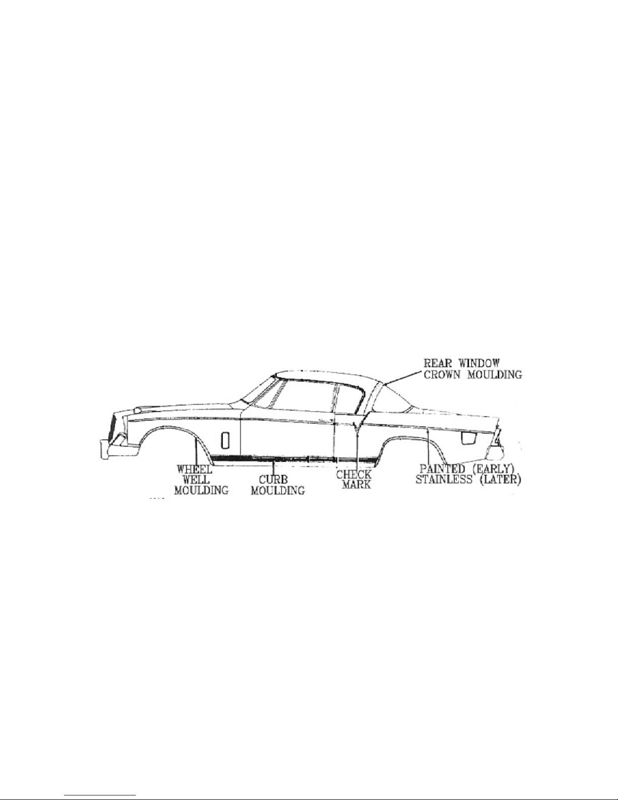
SECTION 2 - Exterior
Mirrors, Outside Rear View
The parts book lists three mirrors, AC-2728, AC-2836, and AC2861 for 1953 through 1957. AC-2728 appeared on the original
production orders for 44 cars (photo 7).
Neither AC-2836 nor AC-2861 appeared on any original
production orders. There was an emblem on the back of mirror
AC-2861 which contained the Studebaker crest similar to that
used on the hubcap and horn button. All the mirrors numbered
AC-28nn were not for 1956 models.
This item was usually sent with the car, but not installed. Probably many dealers sold a customer
a mirror from their existing stock which may or may not have been one of the mirrors shown here.
Reference Source:
1953 - 1958 Body Parts Catalog, page 23.
Various factory photos.
Mouldings, Curb and Wheel Well
AC-2728 Side View Mirror
There are three wide curb mouldings which
run from the rear of the front wheel well,
across the bottom of the door, to the front of
the rear wheel well. There is a right and left
side for the front and rear piece, but the door
moulding is the same for either side. The moulding does not mount on the rocker panel, but
rather, is even with the bottom edge of the door.
All 1956 Golden Hawks came equipped with stainless steel wheel well
mouldings.
Reference Source:
1955 - 1958 Chassis Parts Catalog, pages 480, 485.
1953 - 1958 Body Parts Catalog, page 276.
The Wheelbarrow Johnny, First Quarter 1972, Vol. V, No. 1 page 10.
Last Update - July 2, 2018
Page 59

SECTION 2 - Exterior
Moulding, Front Fender and Door
There is a left and right side stainless moulding on the
front fender. There is a slight bow upward from the ends
to the center of each piece. This is true of the rear
quarter moulding that runs from the Check Mark to the
tail light.
1957 and later Hawks used a straighter front fender moulding which allowed the pieces to be
interchangeable from one side to the other. The 1957 and later front fender and rear quarter
mouldings, with a different fin, will not fit correctly on 1956 Hawks.
The door side mouldings will fit on either side and are the same as the ones used on the 1957 1958 Silver Hawks.
Reference Source:
1955 - 1958 Chassis Parts Catalog, pages 480, 486.
1953 - 1958 Body Parts Catalog, page 273.
Moulding, Outer Rear Fender
The outer rear fender moulding used on the rear quarter panel
at the base of the fin and behind the "V" or "Check Mark" was
painted, not stainless steel, for cars prior to body number 469.
The moulding was
changed to stainless
steel, and was also
larger, beginning with body number 469 when the new
paint scheme was introduced.
Reference Source:
1955 - 1958 Chassis Parts Catalog, page 486.
Hot Rod Magazine dated April 1956, page 17.
Motor Life dated October 1956, page 54.
Moulding, Rear Fender Check Mark "V"
The rear fender "Check Mark"
moulding was changed, also
beginning with body number
469.
When the larger, stainless
moulding was added to the
rear quarter panel, the cutout
at the rear of the "Check Mark"
moulding was enlarged to fit around the new moulding.
This change also coincided with the new paint scheme.
Reference Source:
1955 - 1958 Chassis Parts Catalog, page 486.
Hot Rod Magazine dated April 1956, page 17.
Last Update - July 2, 2018
Page 60

SECTION 2 - Exterior
Moulding, Upper Reveal, Back Window
The back window has a large moulding about 3
inches wide and runs from the belt line on one
side, across the top, to the belt line on the other
side. This is called the Back Window Upper
Reveal Moulding. Many people call this the
crown moulding. It was not used on the other
Hawk models for 1956.
Some confusion has resulted with this so called
crown moulding due to a name change in 1956.
A similar moulding was introduced on the 1955
Speedster (part number 310613), however, the
parts catalogs refer to this item as the Rear
Roof Moulding.
The moulding on the Speedster is mounted
further forward on the roof. A thinner moulding,
part number 303570, went behind the rear roof
moulding and right against the top of the back
window. Unfortunately, this thinner moulding
was also called the Back Window Upper Reveal
Moulding.
For 1956, the crown moulding, with its new
name, was moved to the rear slightly to butt up
to the rear window. This eliminated the need for
the thinner upper reveal moulding used in 1955. Actually, the crown moulding for 1956 was
renamed and in fact replaced the Back Window Upper Reveal Moulding used in 1955. The part
number for 1956 (and 1957-58) Golden Hawks is 1512531. Hopefully, the graphics at the top of
this page will more clearly demonstrate this confusing condition.
The belt mouldings which mount on the body below windshield and side windows were eliminated
for 1956, but returned in 1957.
Reference Source:
Various factory photographs.
1953 - 1958 Body Parts Catalog, pages 265-266, 276, 335.
The Wheelbarrow Johnny, First Quarter 1972, Vol. V, No. 1 page 8.
Last Update - July 2, 2018
Page 61
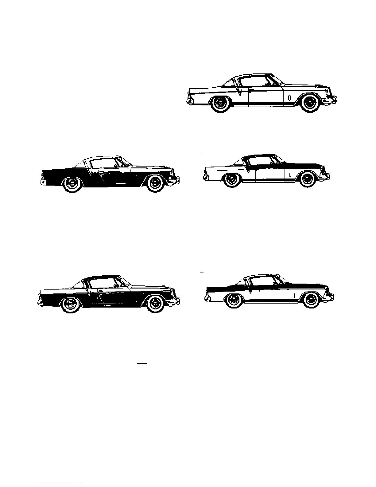
SECTION 2 - Exterior
Paint - Early and Late Schemes
There were three paint schemes used on the
1956 Golden Hawk. The solid color was
available throughout the model run (photo 3).
On cars with body number 1 - 468, the
moulding between the tail light and the
"Check Mark" would be painted the same as
the body color instead of stainless steel.
TYPE 2 - EARLY TWO TONE
TYPE 1 - SOLID COLOR
The second type was used on body numbers 1 - 468. The last one to have this paint scheme,
serial number 6030274, had a final assembly date of November 18, 1955. In this scheme, the
"accent" color was painted on the roof, hood and the area above the side body trim and forward
of the "Check Mark" moulding. The "body" color was painted on the trunk, fins, and lower body
below the side trim.
TYPE 3 - TWO TONE
The third scheme was used for the remainder of the model run. The "body" color was painted on
the roof and the lower portion of the lower body below the side trim. The "accent" color was
painted on the hood, trunk, and area above the side body trim (photo 2).
The body numbers were not assigned in order.
Serial # Body # Serial # Body #
6030274 468 Last of the old style. 6800238 406
6030289 470 6800239 407
6030291 467 6800240 403
6030296 469 First of the new style. 6800242 408
Reference Source:
Review of the original production orders.
1955 - 1958 Chassis Parts Catalog, page 486.
Painting Or Trimming Information Document P-5600
Last Update - July 2, 2018
Page 62

SECTION 2 - Exterior
Last Update - July 2, 2018
Page 63

Paint Colors
SECTION 2 - Exterior
Last Update - July 2, 2018
Page 64

SECTION 2 - Exterior
Last Update - July 2, 2018
Page 65

SECTION 2 - Exterior
April 1956
NOTE: Combination No_ 5642 -Tangerine and Snowcap White has been discontinued.
Effective immediately, all two-tone combinations except No. 5637, 5638 and No. 5641 may be
ordered for Champion and Commander Sedanets.
Last Update - July 2, 2018
Page 66

Parking Light Assembly
front edge of the fender.
SECTION 2 - Exterior
The parking lights on all 1956 Golden Hawks are the same as
those used on all 1956 and1957 Hawks. For 1956, they are
located about 2-1/2" from the front edge of the fender,
excluding the headlight rim.
Although the 1957 Hawk
models have the same parking
light assembly, they are not at
the same location as on 1956
Hawks. On 1957 Hawks, they
are located about 1" from the
For the 1958 Hawk models, a
slightly different parking light assembly was used. The new design
featured wings attached to the side of the tear drop shaped body.
The body has a slotted area for the wing. The parking light location
on the fender was the same as in 1957. The wings were gold on
the 1958 Packard Hawk.
Reference Source:
1955 - 1958 Chassis Parts Catalog, page 176.
Various photos.
Rear Fender Fin
The fin positioned atop the rear fender was made of
fiberglass. The fin was only used on the 1956 Golden
Hawk. It was not used on the other Hawk models for
1956. There is a left and a right side and each runs
between the "Check Mark" moulding and the tail light.
1957 through
1961 Hawk
models used a
completely restyled fin which was made of steel. It was
larger and slanted outward from the body.
Reference Source:
1955 - 1958 Chassis Parts Catalog, page 484.
The Wheelbarrow Johnny, First Quarter 1972, Vol. V, No. 1 page 10.
Various photos.
Last Update - July 2, 2018
Page 67

SECTION 2 - Exterior
Tail Light Housings
The tail light housing on the 1956 Golden Hawk differs from other 1956
Hawks in that a small cutout is present on the outside edge. This cutout
mates up to the outer side of the fiberglass fin. Consequently, there is a
right and a left tail light housing.
The tail light housing used on other Hawk models for 1956 did not have the
cutout because these models did not have a fin. Therefore, the same tail
light housing can be used on either side.
Reference Source:
1955 - 1958 Chassis Parts Catalog, page 213.
Hot Rod Magazine dated April 1956, page 17.
Trunk or Deck Lid and Trunk Script
The trunk lid was the same for all 1956 Hawks and was used for the
1956 model year only. The rear portion of the trunk lid contains
horizontal grooves. On two tone models, this rear portion was
painted to match the contrasting color of the rest of the trunk lid.
The emblem and escutcheon combination was also used for just the
one model year. There is a flattened area around this entire portion
of the deck lid.
The escutcheon was discarded on 1957 and later Hawks.
The key hole was moved up higher on the deck lid and the
flattened area around the keyhole is much smaller.
The "GOLDEN HAWK" trunk script is chrome on most
models. Gold "GOLDEN HAWK" script was introduced with
Studebaker Engineering Master Change Notice No. 22257 (4-4-56). The gold script was used on
some of the South Bend cars produced later in the model year, somewhere around serial number
6032710. All Los Angeles assembled cars appear to have been fitted with the chrome trunk script.
If any Los Angeles cars were fitted with the gold trunk script, it would probably have occurred on
or after serial number 6800519.
The interior of the trunk was painted gray.
Reference Source:
1956 Studebaker Accessories, pages 5, 8.
1953 - 1958 Body Parts Catalog, page 344.
1955 - 1958 Chassis Parts Catalog, page 437.
Studebaker Engineering Master Change Notice No. 22257 (4-4-56).
Studebaker Division letter to R. Biddle from L.H. Lein (4-12-56).
Motor Trend dated February 1956, page 20.
Survey results.
Last Update - July 2, 2018
Page 68

SECTION 2 - Exterior
Wheels and Tires
The wheels on all 1956 Golden Hawks were painted to match the
"body" color, the lower portion of the body.
Four of the two tone color
combinations featured Snowcap White
as the "body" color and therefore had
the wheels painted white. See the
paint color chart Section 5.
The tire size is 7.10 x 15 and if so equipped, the white wall width is approximately 2-1/2 inches.
Many cars were fitted with 6 ply tires.
Reference Source:
1956 Passenger Car Shop Manual, section 17, page 2.
Ditzler Color Paint chip set, Studebaker 1956, Form 5613.
Various factory photos and magazine features.
Last Update - July 2, 2018
Page 69

SECTION 3 - Interior
Ash Trays
There are three ash trays, two in front and one in the rear seat area and are all chrome.
The front ash trays are mounted in the upper portion of the front
door toward the windshield and have a knob in the top center for
opening.
The rear ash tray is located on the
front of the center arm rest at the
upper edge. It has an indented area
at the top for opening.
Reference Source:
1953 - 1958 Body Parts Catalog, page 300.
Motor Trend dated February 1956, page 21.
Hot Rod Magazine dated April 1956, page 54.
Carpet
The Daytona Weave carpet has a sewn border around the edges
and a colored vinyl heel pad. The carpet is mounted on top of the
door sill (scuff) plates, not under them. It is in two sections, one for
the front and one for the rear.
On cars equipped with the Ultramatic
transmission, there is an access hole
on top of the transmission hump,
toward the driver's side. There is an
access cover over the hole. The color
of this hole cover is either Black, Dark
Blue, Dark Green, or Rose Mist.
A rubber floor mat was available in "White, Brown, Gray". Carpet
colors were Charcoal Black, Light Blue, Dark Green, and Dark Rose
Mist.
Reference Source:
1956 Passenger Car Shop Manual, figure 82, section 1, page 31-32.
1953 - 1958 Body Parts Catalog, pages 349, 351-353.
Last Update - July 2, 2018
Page 70

SECTION 3 - INTERIOR
Dash Liner and Kick Pad
The color of the dash liner (the area above the carpet
behind the instrument board) is Charcoal Black, Dark Blue,
Dark Green, or Dark Rose Mist. The 7 fasteners are the
same color as the dash liner.
The right and left kick pads
are held in place by the
vent door and a channel
attached to the front door
opening at the windlace.
The colors are Charcoal
Black, Dark Blue, Dark
Green, Dark Rose Mist, Olive Green Dark, Romany Red, Gold,
and Tangerine.
Reference Source:
1953 - 1958 Body Parts Catalog, pages 278 & 280.
Door Handles
The door handles are chrome.
Reference Source:
1953 - 1958 Body Parts Catalog, page 320.
Motor Trend dated February 1956, page 22 (Power Hawk).
Door - Interior Top Moulding
The stainless moulding that runs along the
top of the door is held in place by six screws.
The door lock button is located at the rear of
the moulding and is black.
There is also a stainless moulding that runs along the top of
the rear quarter vinyl padding.
Last Update - July 2, 2018
Page 71

SECTION 3 - INTERIOR
Gearshift Lever and Knob
The gearshift lever is painted black. Some owners have
indicated that their car's gearshift lever was chrome but
no part number is listed in the 1956 Parts Catalog. A
chrome gearshift lever, part number 1540687, is shown
for 1956 Commanders and Presidents.
The gearshift lever knob is painted black. It is a
threaded type and was used on all 1956 and 1957
Studebakers. In 1958, a press type knob was
introduced.
Reference Source:
1955 - 1958 Chassis Parts Catalog, page 264.
Mechanix Illustrated dated April 1956, page 96.
Motor Trend dated February 1956, page 22.
Speed Age dated March 1956, page 25.
Hot Rod Magazine dated April 1956, page 54.
Speed Age dated July 1956, page 20.
Last Update - July 2, 2018
Page 72

SECTION 3 - INTERIOR
Headliner, Dome Light, and Sun Shield or Visor
The headliner is made of a hard board material with small holes
which run in a diagonal direction. There are four sections which
insert into three metal bows and are held up by three plastic bows.
The headliner, bows, and sun shields were white on all cars,
except those with the following color interiors: the headliner, bows,
and sun visors were Light rose mist on cars with Light & Dark Rose
Mist interior, Light green on cars with Light & Dark Green interior,
Light Blue on cars with Light & Dark Blue interior, and Charcoal on
cars with Charcoal & Red interior.
The dome light is located above the driver's side window in the
second panel near the panel’s rear edge. It is chrome with a
black on/off switch.
Sun visors were one of
the following colors: Off
White, Light Rose Mist,
Light Blue, Light Green,
or Charcoal.
Safety padded sun shields were offered as special
equipment in the following colors: Off White, Light Rose
Mist, Light Blue and Light Green. The parts catalog states
that these three colored visors have a vinyl cover, but no
binding.
Light Rose Mist and Charcoal Black were also offered in
the safety padded sun shield.
A silver mylar band runs above the side
windows from front to back at the bottom of
the headliner.
Reference Source:
1953 - 1958 Body Parts Catalog, pages 355-356.
Survey results.
Last Update - July 2, 2018
Page 73

SECTION 3 - INTERIOR
Instrument Board, Toggle Switches and Gauges
The instrument (dash) board is painted black. The vinyl safety pad cover is Charcoal Black.
Gauges
The Stewart Warner gauges are black with white letters and numerals with the exception of the
vacuum gauge. The vacuum gauge was only used on the 1956 Golden Hawk for the one model
year.
A slightly different gauge, which measured both
vacuum and pressure was used on the
supercharged 1957-58 Golden Hawks. This was
necessary because of the added supercharger.
In this photo, the 1956 vacuum gauge is on the
left and the 1957 gauge is on the right.
Last Update - July 2, 2018
Page 74

SECTION 3 - INTERIOR
Clock
The clock was moved to the right of the radio on the
1956 Golden Hawk. This was necessary because the
tachometer took up the space where the clock
appeared on the other Hawk models for 1956.
The Borg Instruments clock was produced by the
George W. Borg Corporation, and looked similar in
design to the Stewart Warner gauges that dotted the
instrument panel. There was a little slotted pin at the
top of the dial by which the speed could be adjusted to
run faster or slower.
The black face contained white numerals and white
hour and minute hands. The hand that indicated the
seconds was painted red. The clock was illuminated by
one #57 light bulb, and serviced by a one AG 3 amp fuse.
The clock was held in place by two zinc plated brackets which
attached to screws on the back of the clock.
Reference Source:
Engineering drawing for 1540120.
Engineering drawing for 1540242.
Speedometer
The 1956 Golden Hawk featured a 160 MPH Stewart
Warner speedometer. The other Hawk models used a
similar model that registered 120 MPH.
Last Update - July 2, 2018
Page 75

SECTION 3 - INTERIOR
Electrical-Lamp Bulbs
Unit Number & Trade Number
Headlamp 2-5400
Headlamp beam indicator 1-53
Parking light 2-1034
Tail light 2-1034
Stop light 2-1034
Direction Indicator Front 2-1034*
Direction Indicator Rear* 2-1034
Direction Indicator Tell-Tale 2-53*
License plate light 1-67
Instrument light 3-57
Ignition lock light -
Map light - -
Dome light 1-1004
Clock light 1-57*
Radio dial light 2-1891*
Glove compartment light 1-57
Courtesy light - -
Trunk compartment light 1-1003*
Auto. Trans. Shift ndicator Light 1-53*
Cigar Lighter Light 1-53*
Back Un Lamp Light 2-1073*
Hand Brake Warning light. 1-57*
* = Not Standard Equipment
Reference Source:
1956 Passenger Car Shop Manual, Electrical section, page 2.
1956 Automobile Manufacturers Association Consolidated Specification Questionnaire.
Last Update - July 2, 2018
Page 76
SECTION 3 - INTERIOR
Electrical-Fuse & Circuit Breaker Data
Ue trade number of fuse e. g., SFE-l0. Indicate. circuit breaker by ampere capacity suffixed by
letter. "C.B", e.g., 30 C.B. Where fuse or circuit breaker protects multiple circuit. indicate first
use by a letter and repeat the lame letter for all units protected by the same fuse or circuit breaker,
e.g., Parking light: SFE·10 (a), Direction indicator: same asl (a).
Unit Fuse or Circuit Breaker
Headlamp 20 C .B. ( a)
Headlamp beam indicator Same as ( a)
Parking light Same as ( a)
Taillight Same as ( a)
Stop light 15 C.B. (b)
Direction indicator SFE 9
license plate light Same as ( a)
Instrument light Same as ( a)
Ignition light -
Map light -
Dome light Same as (b)
Clock 1 AG 3
Clock light Same as ( a)
Radio SFE 9
Glove compartment light Same as (b)
Courtesy light -
Trunk compartment light Same as (a)
Other
Windshield Wiper 5 C .B.
Trans. O.D. 3 AG 20
Climatizer and Defroster SFE 14
Reference Source:
1956 Passenger Car Shop Manual, Electrical section, page 2.
1956 Automobile Manufacturers Association Consolidated Specification Questionnaire.
Last Update - July 2, 2018
Page 77

SECTION 3 - INTERIOR
Switches
The toggle switches for the lights and accessories are chrome
with black knobs on the end and are held in place by a chrome
nut.
There is a recessed white area at the end of the knob.
There is a plate above each switch which identifies its function. The switches for the Lights, Inst
Lights, and Wiper were to the left of the steering column.
The Defrost switch, Heat slider knob, and Air switch were to the right of the steering
column. All the toggle switches are held in place by a round chrome plated nut.
The switches were changed for the 1957 model year. The
toggle switches had a silver tip instead of the white recessed
area.
Typical 1957 Switch
Last Update - July 2, 2018
1957 Hawk Toggle Switches and Heat Control Bezel
Page 78

SECTION 3 - INTERIOR
Switches - Heat Valve Control
The Heat Valve control knob is
the only one that is not a
toggle. The knob attaches to a
metal piece that slides along a
slot in the bezel. The bezel
has the word ON stamped on
the left end and the work OFF
stamped on the right end. The
lettering is painted black.
The Heat Valve control bezel
was changed for the 1957
model year. The long slot was
moved from the top edge of the
bezel to the bottom edge. The
word “HEAT” was added to the
center, between the OFF and
ON wording.
Heat Valve Control Bezel For 1956
Heat Valve Control Bezel For 1957
This bezel will not work on the 1956 Hawk models unless it is mounted upside down.
Last Update - July 2, 2018
Page 79

Ignition switch
SECTION 3 - INTERIOR
The ignition switch is at the far left of the instrument panel.
It has four positions which operate as follows:
• Center - All circuits are off.
• Turn to the right - All circuits are on.
• Turn to the extreme right - All Circuits Off except
Ignition and Starter Solenoid.
• Turn to the left - Gas Gage, Temperature Indicator and
Accessories.
Ignition Switch Bezel
The ignition switch bezel is chrome and has the word “START”
stamped and painted black, on the inside rim.
Reference Source:
1953 - 1958 Body Parts Catalog, pages 207 & 294.
Mechanix Illustrated dated April 1956, page 96.
Motor Trend dated February 1956, page 22.
Speed Age dated March 1956, page 25.
Hot Rod Magazine dated April 1956, page 54.
The Wheelbarrow Johnny, First Quarter 1972, Vol. V, No. 1 page 8.
1956 Automobile Manufacturers Association Consolidated Specification Questionnaire.
Last Update - July 2, 2018
Page 80

SECTION 3 - INTERIOR
Parking Brake Warning Lamp
The Parking Brake Warning Lamp was listed as
accessory code AC-2776 and was installed at the
factory on 40 Golden Hawks for 1956.
The lamp itself was located on the lower part of
the instrument panel between the headlamp and
instrument lamp switches. As the name implies,
the red lamp would shine when the parking brake
was applied and the ignition was on.
Only forty Golden Hawks came equipped from the
factory with this accessory and all except six were
exported.
The wiring included a clip that attached to the parking brake mechanism and was activated when
the handled was pulled out to engage rear brakes.
Reference Source
AC2776 Installation Instructions.
1956 Studebaker Accessories Brochure.
1955 - 1958 Chassis Parts Catalog, page 388-389.
1956 Golden Hawk Production orders.
Last Update - July 2, 2018
Page 81

SECTION 3 - INTERIOR
Radio
Both manual "Starliner" (AC-2748) and automatic tuning "Stratoline" (AC-2747) radios came with
a chrome bezel.
The chrome knob on
the right side is a
dummy knob (part
number 1540369) on
the manual tune
radio, but is the rear
seat speaker switch
control knob (part
number 1540370) on
the automatic tune radio. This control knob was
locked in place, by a pin, for the front speaker if
the rear seat speaker option was not included
with the car.
An RCA plug jack for the rear seat speaker wire was on
the right side of the radio, behind the dash, on automatic
tuning radios.
The volume control and tuning
knobs are black with a chrome
center. The rear seat speaker
option was not available on the
manual tune radio.
Reference Source:
1953 - 1958 Body Parts Catalog, pages 15-17.
Check and Price List for Studebaker Salesmen.
1956 Studebaker Accessories, pages 4-5.
Hot Rod Magazine dated April 1956, page 54.
Rear Package Shelf Cover
The rear shelf cover (the area between the back seat and
the back window) is plain and should be one of the following
colors: Black, Dark Blue, Dark Green, Dark Rose Mist, Dark
Olive Green, Romany Red, Gold, or Tangerine.
The four fasteners should be the same color as the cover.
Reference Source:
1953 - 1958 Body Parts Catalog, page 374.
Last Update - July 2, 2018
Page 82

SECTION 3 - INTERIOR
Seat Belts (Karbelts*)
One part of the optional seat belts was mounted on the door and the other part was attached to
the floor behind the front seat. They should be one of the following colors: Gray, Green, Red,
Blue, Brown, or Black.
The seat belt attached to a cable that was bolted to
the floor behind the front seat.
The decal on the buckle is round, about
1" in diameter, has the StudebakerPackard (SP over a V) emblem in the
center, and is red/white/blue.
* Trade Mark Registered
There was also a set of rear belts available .
Reference Source:
1953 - 1958 Body Parts Catalog, pages 22-23.
Check and Price List for Studebaker Salesmen.
1956 Studebaker Accessories, page 8.
The Wheelbarrow Johnny, First Quarter 1972, Vol. V, No. 1 page 9.
Mechanix Illustrated dated April 1956, page 96.
Motor Trend dated February 1956, page 22.
Last Update - July 2, 2018
Page 83

SECTION 3 - INTERIOR
Seat - Lower Panel and Adjustment Lever
The lower seat side panel was vinyl covered and was
available in Black, Dark Blue, Dark Green, White, and
Dark Rose Mist.
The adjustment handle located on the driver side was
chrome.
Reference Source:
1953 - 1958 Body Parts Catalog, pages 339-340.
Seat - Power (Electric)
A total of 345 Golden Hawks came from the factory
equipped with the Power Seat option, 304 from South
Bend and 41 from Los Angeles.
The mechanism is controlled by a toggle type switch
located on the frame below the lower front edge of the
seat, just left of center.
The seat is mounted on curved tracks so that as it
moves forward, it also rises and tips to a more vertical
position. As the seat moves to the rear, it also tips back
and lowers.
There is also a power seat relay switch located on the engine
side of the firewall behind the battery. This same relay also
supplies power to the electric window lifts if the car is so equipped.
Reference Source:
1956 Golden Hawk Production orders.
1956 Passenger Car Shop Manual, Body section, page 26 Fig 68, page 29 Fig 75.
Last Update - July 2, 2018
Page 84

SECTION 3 - INTERIOR
Seat Upholstery
The standard seat material on 1956 Golden Hawks is Kidd Grain vinyl with Silver Spire cloth
inserts. Optional all vinyl upholstery was available for all colors.
The exception was Ceramic Green/Snowcap White (paint code P5641) which came standard with
White & Olive all vinyl upholstery (see the Colors and Upholsteries chart in Section 5). However,
three production orders listed cloth trim for cars with the P5641 paint code. One of those cars still
exists and does have the cloth and vinyl interior.
On cars with all vinyl interiors, the pleats were on
the insert portion and ran from front to rear and top
to bottom.
All Vinyl Interior
On interiors with cloth inserts, the vinyl area in
front of, and above the inserts was pleated and
ran from front to rear. A silver spire cloth
material was used for the cloth insert. The only
colors available for the insert were Charcoal,
Light Blue, Light Green, Dark Taupe (also listed
as Dark Rose Mist).
Silver welt cords separated the bolster from the
insert on both the cloth/vinyl and the all vinyl
seats.
Reference Source:
Color & Upholstery Specifications dated November 1955, page 23.
Revised Color & Upholstery Specifications, April 1956, page 11.
Review of the original production orders.
Mechanix Illustrated dated April 1956, pages 96-97.
Motor Trend dated February 1956, page 21.
Last Update - July 2, 2018
Page 85

SECTION 3 - INTERIOR
Drawing courtesy Southeast Studebaker
Last Update - July 2, 2018
Page 86

SECTION 3 - INTERIOR
Seat Upholstery - Color/Fabric Combinations
Last Update - July 2, 2018
Page 87

SECTION 3 - INTERIOR
Last Update - July 2, 2018
Page 88

SECTION 3 - INTERIOR
Last Update - July 2, 2018
Page 89
Side Panels, Interior
SECTION 3 - INTERIOR
The vinyl side panels feature built in
armrests and a brick pattern silver mylar
insert between the two upper
mouldings. All indications are that the
mylar was gold on cars painted Ceramic
Green/Snowcap White.
The upper portion of the side panel has
2" dielectric seams which run downward
and forward. The lower portion has 3/4"
horizontal dielectric seams.
Reference Source:
Various factory photos.
Factory brochures.
The Wheelbarrow Johnny, First Quarter 1972, Vol. V, No. 1 page 8-9.
Southeast Studebaker
MYLAR & BUILT IN ARMREST
Last Update - July 2, 2018
Page 90

SECTION 3 - INTERIOR
Steering Wheel and Horn Button
The steering wheel, part number 1540647, is white with a 17"
diameter. The part number is stamped on the back side of the
vertical spoke about 1" below the center hub.
The horn ring is chrome and is a half circle, with a vertical
spoke, on the lower half of the wheel.
There are two chrome
11/32" rings which encircle
the rim on each side above
the horizontal bar. One is
about ½" above the
horizontal bar and the
second is located about 4-
1/2" beyond the first. The
area between the two chrome rings is ribbed. The remainder
of the steering wheel is smooth.
The part number is stamped on a flattened area of the rear of
the vertical spoke.
Steering Wheel Assy. 1540647 (17-¼” overall diameter)
Engineering Release Date: 9/8/55 (Superceded steering wheel
assy. 1539788X41 for 56J). 1539788X41was a black steering
wheel and probably appeared on the first two show cars
before this change was implemented. There is also a
Studebaker advertisement showing a 1956 Golden Hawk with
a black steering wheel.
There was a similar wheel available for
Sedans and Station Wagons with an 18"
diameter. This wheel can be identified by
the part number 1540635, on the reverse
of the vertical spoke. The number "18" is
also stamped on the front side of the
same spoke between the side rails near
the center hub. This wheel looks exactly
the same as the correct Golden Hawk 17"
wheel except that it is 1" larger in diameter.
The horn button is gold with the Studebaker crest, similar to the grille
emblem, in the center.
Reference Source:
1955 - 1958 Chassis Parts Catalog, page 413.
Mechanix Illustrated dated April 1956, page 96.
Motor Trend dated February 1956, page 22.
Hot Rod Magazine dated April 1956, page 54.
Speed Age dated July 1956, page 20.
Engineering Change Proposal Release Date: 9/8/55
Last Update - July 2, 2018
Page 91

SECTION 3 - INTERIOR
Ultramatic Transmission Selector Indicator Dial
The selector indicator dial was used on the 1956 Golden Hawk only.
There is a triangle on either side of the "D" location to indicate the two
Drive positions.
The selector positions from left to right:
P - Park
R - Reverse
N - Neutral
D - High (Triangle to Left of the D)
D - Drive (Triangle to Right of the D)
L - Low
Gear Ratios:
High -Torque Converter, High, Automatically Upshifting to Direct Drive
Drive - Torque Converter plus 1.82 Gear Ratio, Automatically Upshifting to High Direct Drive
Low - Torque Converter plus 1.82 Gear Ratio
Reverse - Torque Converter plus 1.82 Gear Ratio
Reference Source:
1953 - 1958 Body Parts Catalog, page 313.
1956 Passenger Car Shop Manual, figure 260, section 16, page 112.
1956 Automobile Manufacturers Association Consolidated Specification Questionnaire.
Window Crank Handles
The window crank handles are chrome. The knobs are black with
chrome centers.
Reference Source:
1953 - 1958 Body Parts Catalog, page 320.
Motor Trend dated February 1956, page 22 (Power Hawk).
Last Update - July 2, 2018
Page 92
SECTION 3 - INTERIOR
Windows - Power (Electric Lifts)
A total of 488 Golden Hawks came from the factory
equipped with Power Windows, 398 from South Bend
and 90 from Los Angeles.
There was a double switch on the driver side door which
allowed the driver to operate both front door windows.
A single switch was
on the passenger
side door. There
was no po wer
w i n d o w o p t i o n
available for the
rear quarter windows.
There is also an electric window lifts relay switch located
on the driver's side of the firewall behind the battery.
This same relay also supplies power to the power seat.
Reference Source:
1956 Golden Hawk Production orders.
1956 Passenger Car Shop Manual, Body section, page 21-26 Fig 68.
Windshield and Back Window Opening Garnish Mouldings
The windshield interior mouldings (4 pieces including
the mirror bracket) were changed from stainless steel
to black painted mouldings some time late in the
production run. The parts manual states that this
occurred after approximately 4925 cars. This total
must include the 1956 Sky Hawk Hardtop, and the
rare 1956 Flight Hawk Hardtop.
Since there were only 4071 (4073 minus the two that
were scrapped) 1956 Golden Hawks, it isn't possible to pin this change to a particular serial
number. In our survey, the change appears to have occurred around serial number 6032791 (420-56). The Los Angeles counterpart would be approximately serial number 6800527 (5-1-56).
The 4 piece back window garnish moulding
and clip group was stainless steel. The parts
catalog shows no sign that the back window
garnish moulding was changed to the black
painted surface (as were the windshield
opening garnish mouldings described
above). A few survey members indicated the
rear mouldings on their car were painted, but
were not sure if they were original.
WINDSHIELD GARNISH MOULDING
Reference Source:
1953 - 1958 Body Parts Catalog, pages 334-335 & 360-361.
Hot Rod Magazine dated April 1956, page 54.
Survey results.
Last Update - July 2, 2018
Page 93

SECTION 4
Trunk Compartment
Jack and Jack Base
There are two different part numbers listed for the jack, less base, for U.S.A. cars plus a third
number for station wagons. A fourth number is listed for Canada cars. I assume this means
"exported to" Canada.
The 1955, 1956, 1957, and 1958 models all used a different style jack and jack ba se.
Two part numbers are also shown for the jack base for 1956 models. My guess is that one is for
Hawks and one is for the other Studebaker models. The parts book shows a different part number
for Canada cars.
The jack riser mechanism and the jack base should be painted black enamel. The base supplied
by Universal Tool & Stamping Company, Part # 1539037, was 7.5" square with the corners cut
at a45 degree angle, and the height was 1-3/8".
Reference Source:
1955 - 1958 Chassis Parts Catalog, page 531.
Engineering drawing for 1539037
Spare Tire Hold Down Clamp
The spare wheel clamp is a round metal plate with a hole in the
center and should be painted black. It is held down by a large
bolt size ½" - 13 x 6-1/4".
Reference Source:
1955-1958 Chassis Parts Catalog, page 445.
1953-1958 Body Parts Catalog, page 343.
Motor Trend dated February 1956, page 20.
Mechanix Illustrated dated April 1956, page 96.
Trunk Interior Color
The interior of the trunk is gray in color and includes the floor pan, side walls, cross braces behind
the back seat, the under side of the trunk lid, and
the under side of the package shelf.
Reference Source:
Survey results.
Last Update - July 2, 2018
Page 94

Trunk Compartment
Trunk Mat
The trunk mat is a woven fabric which the parts catalog lists as "White, Brown, Gray" (photo 26).
The hounds tooth pattern as used on later model Hawks does not appear to be the correct one
for 1956.
Reference Source:
1953 - 1958 Body Parts Catalog, page 351.
Motor Trend dated February 1956, page 20.
Science and Mechanics dated April 1956, page 76.
Last Update - July 2, 2018
Page 95

SECTION 5
Paint, Upholstery and Accessory Charts
PAINT COLORS
1956 Studebaker Solid Colors
CODE COLOR
----- -----------------------------------------------------------P5610 SUNGLOW GOLD (GOLDEN HAWK AND SKY HAWK ONLY)
P5611 MIDNIGHT BLACK
P5612 SNOWCAP WHITE
P5613 DAYBREAK BLUE
P5614 AIRFORCE BLUE
P5615 SEASIDE GREEN
P5616 GLENBROOK GREEN
P5617 CAMBRIDGE GRAY
P5618 YELLOWSTONE
P5619 ROMANY RED (HAWK MODELS ONLY)
Two Tone Color Combinations
CODE LOWER COLOR: TOP COLOR: WHEELS
(BASIC) (ACCENT)
----- -------------- ------------------ ------------------P5620 AIRFORCE BLUE DAYBREAK BLUE AIRFORCE BLUE
P5621 DAYBREAK BLUE AIRFORCE BLUE DAYBREAK BLUE
P5622 DAYBREAK BLUE SNOWCAP WHITE DAYBREAK BLUE
P5623 AIRFORCE BLUE SNOWCAP WHITE AIRFORCE BLUE
P5624 GLENBROOK GREEN SEASIDE GREEN GLENBROOK GREEN
P5625 SEASIDE GREEN GLENBROOK GREEN SEASIDE GREEN
P5626 SEASIDE GREEN SNOWCAP WHITE SEASIDE GREEN
P5627 GLENBROOK GREEN SNOWCAP WHITE GLENBROOK GREEN
P5628 CAMBRIDGE GRAY SNOWCAP WHITE CAMBRIDGE GRAY
P5629 MIDNIGHT BLACK SNOWCAP WHITE MIDNIGHT BLACK
P5630 SNOWCAP WHITE MIDNIGHT BLACK SNOWCAP WHITE
P5631 ROMANY RED MIDNIGHT BLACK ROMANY RED
P5632 MIDNIGHT BLACK ROMANY RED MIDNIGHT BLACK
P5633 SNOWCAP WHITE ROMANY RED SNOWCAP WHITE
P5634 ROMANY RED SNOWCAP WHITE ROMANY RED
P5635 SNOWCAP WHITE SUNGLOW GOLD SNOWCAP WHITE
P5636 SUNGLOW GOLD SNOWCAP WHITE SUNGLOW GOLD
P5637 MOCHA DOESKIN MOCHA
P5638 MOCHA SNOWCAP WHITE MOCHA
P5639 YELLOWSTONE MIDNIGHT BLACK YELLOWSTONE
P5640 YELLOWSTONE SUNGLOW GOLD YELLOWSTONE
P5641 CERAMIC GREEN SNOWCAP WHITE CERAMIC GREEN
P5642 TANGERINE SNOWCAP WHITE TANGERINE
P5664 ROSEBUD SNOWCAP WHITE ROSEBUD
P5665 REDWOOD SNOWCAP WHITE REDWOOD
P5666 SNOWCAP WHITE REDWOOD SNOWCAP WHITE
P5667 MIDNIGHT BLACK SEASIDE GREEN MIDNIGHT BLACK
P5668 CAMBRIDGE GRAY DAYBREAK BLUE CAMBRIDGE GRAY (ASSUMED)
P5669 YELLOWSTONE SNOWCAP WHITE YELLOWSTONE (ASSUMED)
Last Update - July 2, 2018
Page 96

Colors and Upholsteries - - Standard and Optional 56j-k7 Golden Hawk
COLORS UPHOLSTERIES
PAINT
NO.
P5610 SUNGLOW gold 8414 WC None 8446 WGO 8440 WC
P5611 MIDNIGHT black 8414 WC 8415 BL
P5612 SNOWCAP white 8416 GRN 8414 WC
P5613 DAYBREAK blue 8415 BL 8441 BL
P5614 AIRFORCE blue 8415 BL None 8441 BL
P5615 SEASIDE green 8416 GRN None 8442 GRN
P5616 GLENBROOK green 8416 GRN None 8442 GRN
P5617 CAMBRIDGE gray 8414 WC None 8445 WRD 8440 WC 8447 CR
P5618 YELLOWSTONE 8414 WC None 8446 WGO 8440 WC
P5619 ROMANY red 8414 WC None 8445 WRD 8440 WC 8447 CR
P5620 AIRFORCE blue DAYBREAK blue 8415 BL None 8441 BL
P5621 DAYBREAK blue AIRFORCE blue 8415 BL None 8441 BL
P5622 DAYBREAK blue SNOWCAP white 8415 BL None 8441 BL
P5623 AIRFORCE blue SNOWCAP white 8415 BL None 8441 BL
P5624 GLENBROOK green SEASIDE green 8416 GRN None 8442 GRN
P5625 SEASIDE green GLENBROOK green 8416 GRN None 8442 GRN
P5626 SEASIDE green SNOWCAP white 8416 GRN None 8442 GRN
P5627 GLENBROOK green SNOWCAP white 8416 GRN None 8442 GRN
P5628 CAMBRIDGE gray SNOWCAP white 8414 WC None 8445 WRD 8440 WC 8447 CR
P5629 MIDNIGHT black SNOWCAP white 8414 WC None 8445 WRD 8440 WC
P5630 SNOWCAP white MIDNIGHT black 8414 WC None 8445 WRD 8440 WC
P5631 ROMANY red MIDNIGHT black 8414 WC None 8445 WRD 8440 WC 8447 CR
P5632 MIDNIGHT black ROMANY red 8414 WC None 8445 WRD 8440 WC 8447 CR
P5633 SNOWCAP white ROMANY red 8414 WC None 8445 WRD 8440 WC
P5634 ROMANY red SNOWCAP white 8414 WC None 8445 WRD 8440 WC
P5635 SNOWCAP white SUNGLOW gold 8414 WC None 8446 WGO 8440 WC
P5636 SUNGLOW gold SNOWCAP white 8414 WC None 8446 WGO 8440 WC
P5637 MOCHA DOESKIN 8417 RO None 8448 WRO 8443 RO
P5638 MOCHA SNOWCAP white 8417 RO None 8448 WRO 8443 RO
P5639 YELLOWSTONE MIDNIGHT black 8414 WC None 8446 WGO 8440 WC
P5640 YELLOWSTONE SUNGLOW gold 8414 WC None 8446 WGO 8440 WC
P5641 CERAMIC green SNOWCAP white None None 8444 WO
P5642 TANGERINE SNOWCAP white 8414 WC None 8450 WT 8440 WC
P5664 ROSEBUD SNOWCAP white 8414 WC 8440 WC
P5665 REDWOOD SNOWCAP white 8414 WC 8440 WC
P5666 SNOWCAP white REDWOOD 8414 WC 8440 WC 8443 RO 8448 WRO
P5667 MIDNIGHT black SEASIDE green 8416 GRN 8440 WC 8442 GRN
BL Lt. Blue & Dk. Blue WC White & Charcoal WRD White & Red
CR Charcoal & Red WGO White & Gold WRO White & Rose Mist
GRN Lt. Green & Dk. Green WO White & Olive WT White & Tangerine
RO Lt. & Dk Rose Mist (Taupe)
SOLID OR BASIC ACCENT
KEY TO UPHOLSTERY SYMBOLS:
STANDARD | OPTIONAL
CLOTH & VINYL
OPTIONAL
ALL-VINYL
8445 WRD 8441 BL
8440 WC 8446 WGO 8447 CR
8445 WRD 8440 WC
8447 CR 8442 GRN 8446 WGO
8447 CR 8446 WGO
8447 CR 8446 WGO
Page 97

1956 Studebaker Golden Hawk Equipment List
Taken from the Original Production Orders
. . . . . . . . . . SB LA TOTAL
SAFETY PADDED DASH 'CRASH PAD' (15). . . . . . 0 1 1
AIR CONDITIONING (16). . . . . . . .. 1 0 1
POWER SEAT (18). . . . . . . . .. .304 41 345
POWER WINDOW (20) . . . . . . .. 398 90 488
TINTED GLASS (23) . . . . . . . . 1590 573 2163
ELECTRIC WIPERS (24) . . . . . . .. 1 592 593
OVERDRIVE TRANS (27). . . . . . . .. 709 77 786
AUTO TRANS (28). . . . . . . . .. 2763 524 3287
OIL FILTER (33). . . . . . . . .. 2 1 3
POWER STEERING (35). . . . . . . .. 1936 425 2361
HIGH POWER KIT (37). . . . . . . .. 2 1 3
* UNKNOWN (40) * * . . . . . .. 0 3 3
WET AIR CLEANER 'WAC' (41). . . . . . .. 8 598 606
HEAVY DUTY SPRINGS & SHOCKS (42) . . . . . 166 0 166
HEAVY DUTY SHOCKS FRONT . . . . . .. 1 0 1
HEAVY DUTY ADJUSTABLE SHOCKS . . . . . . 56 0 56
HEAVY DUTY SPRINGS . . . . . . .. 93 0 93
HEAVY DUTY SPRINGS FRONT . . . . . . 1 0 1
BELG TYPE SPRINGS . . . . . . . 5 0 5
HILL HOLDER (48). . . . . . . . .. 1 1 2
POWER BRAKES (51). . . . . . . . . 1558 262 1820
WHITE WALL TIRES (55) . . . . . . .. 3150 576 3726
DIRECTIONAL SIGNALS (61) . . . . . . . 3384 588 3972
DELUXE STEERING WHEEL (72). . . . . . . 27 15 42
* UNKNOWN (82) * * . . . . . .. 0 6 6
5 BLADE FAN . . . . . . . . . 1 0 1
6 BLADE FAN . . . . . . . . . 1 0 1
AXLE 3.54, PINION 537704 . . . . . . .. 19 1 20
AXLE 3.73, PINION 537704 . . . . . . .. 11 0 11
AXLE 4.09, PINION 529060 . . . . . . .. 9 2 11
AXLE 4.27, PINION 534806 . . . . . . .. 5 1 6
AXLE 4.55, PINION 529061 . . . . . . .. 5 4 9
HC HEAD * * . . . . . .. 3 0 3
950 TO 1 CYL HEAD * * . . . . . . 1 0 1
LC HEAD, 825 TO 1 CYL HEAD
LUG LITE (1312907) . . . . . 64 0 64
METRIC SPEEDOMETER . . . . . . .. 143 0 143
SAFETY PADDED SUNVISORS. . . . . . .. 13 0 13
SSF UNDERCOATING . . . . . . . 16 0 16
UNDER HOOD LIGHT (AC-2442?). . . . . . . 0 0 0
AC-235 LOCKING FILLER CAP, GAS TANK . . . . . 25 0 25
* (AC-1708) *ROLON TIRE CHAINS 7:10 X 15 COMMANDER. . . . 1 0 1
AC-1855 MIRROR, VISOR VANITY. . . . .. 21 0 21
AC-2028 FRONT FENDER SPLASHGUARDS, PAIR. . . . 6 0 6
AC-2029 COVER, ACCELERATOR PEDAL. . . . . 8 0 8
AC-2302 SPEAKER KIT, REAR SEAT (USE AC-2777). . . . 560 55 615
AC-2334 SWITCH KIT, BACK-UP LAMP-LHC
AC-2340 MIRROR, STRAT-O-VUE OUTSIDE (RIGHT OR LEFT SIDE). . 41 0 41
AC-2340 MIRROR, STRAT-O-VUE OUTSIDE (LEFT SIDE ONLY). . 7 0 7
AC-2354 INTERIOR GLARE PROOF TILT MIRROR. . . . 10 0 10
AC-2366 KLEENEX DISPENSER. . . . . .. 13 0 13
AC-2367 MAT, LEFT FRONT FLOOR CARPET - C-K - LHC. . . 18 0 18
AC-2368 MAT, RIGHT FRONT FLOOR CARPET - C-K -LHC. . . 15 0 15
AC-2425 CAP AND DISK, HUB (WIRE WHEEL) (63). . . . 46 57 103
AC-2444 SWITCH KIT, BACK-UP LAMP-LHC
* (AC-2481) *STAINLESS STEEL WHEEL TRIM RING. . . . . 3 0 3
* (AC-1401) *RING, WHEEL TRIM - STAINLESS STEEL . . . . 1 0 1
AC-2495 REGAL LICENSE PLATE FRAME (PLASTIC WINDOW). . 0 0 0
* (AC-2497) *SPORTSTER HUB (SPINNER) FOR AC-2492 & AC-2314 COVERS 1 0 1
AC-2688 ANTENNA KIT, INTERNALLY CONTROLLED (68). . . 2134 472 2606
AC-2689 ANTENNA KIT, FRONT EXTERNALLY CONTROLLED (67). . 291 18 309
AC-2699 DOOR HANDLE GUARDS, PAIR. . . . .. 15 0 15
AC-2704 GAS DOOR GUARD. . . . . . . 2 0 2
AC-2728 MIRROR, SUPER-VUE OUTSIDE (RIGHT OR LEFT SIDE). . 44 0 44
(LEFT SIDE ONLY) . . . . . . 16 0 16
* (AC-2736) *ADAPTER KIT FOR AC-2366 TISSUE DISPENSER . . 1 0 1
AC-2738 CAP AND DISK, HUB (FULL DISK) 15" EQUIP (62) . . 2797 481 3278
AC-2743 LICENSE PLATE FRAME. . . . . .. 8 0 8
* (AC-2744) *(BUMPER GUARD KIT, REAR BUMPER-W-Y-F, SEDAN MODELS). 6 0 6
AC-2747 RADIO, "STRATOLINE" AUTOMATIC TUNING - C-K (66). . 2479 500 2979
(ENGINE XH, USED ON EXPORT MODELS) . . 58 0 58
(WITH ST, AND OD LESS POWER STEERING). .. 239 0 239
(WITH ST, AND OD WITH POWER STEERING) .. 83 0 83
Last Update - July 2, 2018
Page 98

1956 Studebaker Golden Hawk Equipment List
Taken from the Original Production Orders
. . . . . . . . . . . . SB LA Total
* (AC-2745) *RADIO, "STRATOLINE" AUTOMATIC TUNING - W-Y-F-D SEDANS. 1 0 1
AC-2748 RADIO, "STARLINE" MANUAL TUNING - C-K (65). . . 210 15 225
* (AC-2746) *RADIO, "STARLINE" MANUAL TUNING - W-Y-F-D SEDANS 1 0 1
AC-2750 CIGAR LIGHTER COMPLETE (75). . . . . 3127 567 3694
AC-2752 LIGHT, COMPARTMENT - C-K. . . . . 3 0 3
AC-2754 DEFLECTOR, OUTLET PIPE (incls. screw) C-K. . . 82 0 82
AC-2756 CLOCK KIT, ELECTRIC (74). . . . . . 3056 554 3610
* (AC-2755) *CLOCK KIT, ELECTRIC W-F-E-P-Y (SEDANS). . . . 4 0 4
AC-2762 BACK-UP LAMP KIT - C-K-D (70). . . . . 2247 538 2785
* (AC-2761) *BACK-UP LAMP KIT - W-F-Y (SEDANS) . . . . 1 0 1
AC-2765 SPOTLIGHT ASSEMBLY, LEFT. . . . . 6 0 6
AC-2766 SPOTLIGHT ASSEMBLY, RIGHT. . . . . 3 0 3
AC-2767 TRUNK AND UTILITY LIGHT EQUIPMENT
* (SP-50056) *(REPLACED BY AC-2767) . . . . . 1 0 1
AC-2769 CLIMATIZER AND DEFROSTER KIT
* (AC-2770) *ANTI-CREEP KIT (NOT USED ON 56J). . . . . 11 0 11
AC-2774 WASHER KIT, WINDSHIELD - LHC (71). . . . 1697 198 1895
* (AC-2499) *WINDSHIELD WASHER . . . . . . 5 0 5
AC-2775 ANTENNA KIT, REAR DUAL, EXTERNALLY CONTR. - C-K (68A). 86 5 91
* (AC-2778) *ANTENNA KIT, REAR DUAL, EXTERNAL CONT. W-F-Y (SEDANS) 10 0 10
AC-2776 KIT, PARKING BRAKE WARNING LIGHT. . . . 40 0 40
AC-2777 SPEAKER KIT, REAR SEAT (69). . . . . 409 40 449
AC-2780 WIRE WHEEL OVERLAY (PROTOTYPE). . . . 84 0 84
AC-2787 AUTO COMPASS. . . . . . . . 2 0 2
AC-2796 COVER KIT, VALVE ROCKER ARM CHROME. . . 0 0 0
AC-2799 CAP AND DISK, HUB (SPOKE TYPE) (81). . . . 208 27 235
AC-2810 GUARD, CHROME DOOR EDGE - SET OF 2 - C-K. . . 0 0 0
AC-2836 MIRROR, STARLINE OUTSIDE (FOR RIGHT OR LEFT SIDE). 0 0 0
AC-2861 MIRROR, REGAL OUTSIDE (FOR RIGHT OR LEFT SIDE). . 0 0 0
SP-50023 CURB ALARM, PAIR. . . . . . . 1 0 1
SP-50048 DELUXE LICENSE PLATE FRAME. . . . . 15 0 15
SP-50049 BRAKE FLUID SAFETY RESERVOIR . . . . 12 0 12
SP-50055 TRAFFIC LIGHT VIEWER . . . . . 2 0 2
SP-5006n___ FRONT SEAT BELT KIT, ALL COLORS (80). . . . 892 92 984
SP-50060 FRONT SEAT BELT KIT, GRAY (80). . . . 869 92 961
SP-50061 FRONT SEAT BELT KIT, GREEN (80). . . . 4 0 4
SP-50062 FRONT SEAT BELT KIT, RED (80). . . . 5 0 5
SP-50063 FRONT SEAT BELT KIT, BLUE (80). . . . 1 0 1
SP-50064 FRONT SEAT BELT KIT, BROWN (80). . . . 6 0 6
SP-50065 FRONT SEAT BELT KIT, BLACK (80). . . . 7 0 7
SP-5007n___ REAR SEAT BELT KIT, ALL COLORS (80A). . . . 22 1 23
SP-50070 REAR SEAT BELT KIT, GRAY (80A). . . . 10 1 11
SP-50071 REAR SEAT BELT KIT, GREEN (80A). . . . 0 0 0
SP-50072 REAR SEAT BELT KIT, RED (80A). . . . 3 0 3
SP-50073 REAR SEAT BELT KIT, BLUE (80A). . . . 2 0 2
SP-50074 REAR SEAT BELT KIT, BROWN (80A). . . . 4 0 4
SP-50075 REAR SEAT BELT KIT, BLACK (80A). . . . 3 0 3
(CORD, REEL, BRACKET, GROMMET, CABLES) . 17 0 17
W/HEATING UNITS-C-K (USA) (60). . . . 3066 422 3488
OVERDRIVE TRANS WITH POWER STEERING . . 160 32 192
OVERDRIVE TRANS WO POWER STEERING . . . 549 45 594
* ITEMS IDENTIFIED WITH AN ASTERISK ARE THOSE WHICH WERE NOT LISTED AS 1956 GOLDEN
HAWK ACCESSORIES.
() NUMERALS IN PARENTHESES FOLLOWING THE DESCRIPTION ARE THE LOS ANGELES EQUIVALENT
TO THE SOUTH BEND AC-NNNN ACCESSORY CODE.
Last Update - July 2, 2018
Page 99

1956 Studebaker Golden Hawk Paint Code Statistics
Taken from the Original Production Orders
PAINT SOUTH LOS
CODE PAINT COLOR BEND ANGELES TOTAL
----- ------------------------------------------------------------- ------------ -------------- ------------
Bad Production Order Bad, Can't Read it 2 0 2
None Probably P5637 or P5638 Based on Trim 1 0 1
Omit No Paint Color Listed . 72 0 72
P5601 Special (See Note 1 Below)
- #1006 Symbol Bag Snowcap White and
#1013 Symbol Ban Yellowstone 1 0 1
- #1000 Symbol Baa Midnight Black and
#1003 Symbol Bad Romany Red 1 0 1
- #1010 Symbol Bak Ceramic Green 6 0 6
P5610 Sunglow Gold . . . . 21 13 34
P5611 Midnight Black . . . . 216 23 239
P5612 Snowcap White . . . . 130 18 148
P5613 Daybreak Blue . . . . 1 0 1
P5614 Airforce Blue . . . . 8 0 8
P5615 Seaside Green . . . . 2 1 3
P5616 Glenbrook Green . . . 2 0 2
P5617 Cambridge Gray . . . . 29 5 34
P5618 Yellowstone . . . 8 2 10
P5619 Romany Red . . . 12 2 14
P5620 Airforce Blue/daybreak Blue . 50* 12 62* (Note 2)
P5621 Daybreak Blue/airforce Blue . 7 11 18
P5622 Daybreak Blue/snowcap White . 27 10 37
P5623 Airforce Blue/snowcap White . 73 11 84
P5624 Glenbrook Green/seaside Green . 48 11 59
P5625 Seaside Green/glenbrook Green . 9 3 12
P5626 Seaside Green/snowcap White . 15 7 22
P5627 Glenbrook Green/snowcap White . 21 4 25
P5628 Cambridge Gray/snowcap White . 96 19 115
P5629 Midnight Black Snowcap/white . 159 21 180
P5630 Snowcap White/midnight Black . 30 14 44
P5631 Romany Red/midnight Black . . 55 7 62
P5632 Midnight Black/romany Red . . 20 6 26
P5633 Snowcap White/romany Red . . 18 13 31
P5634 Romany Red/snowcap White . . 103 24 127
P5635 Snowcap White/sunglow Gold . 51 12 63
P5636 Sunglow Gold/snowcap White . 649 73 722
P5637 Mocha/doeskin . . . . 303 60 363
P5638 Mocha/snowcap White . . 258* 49 307* (Note 2)
P5639 Yellowstone/midnight Black . 36 10 46
P5640 Yellowstone/sunglow Gold . 73 7 80
P5641 Ceramic Green/snowcap White . 676 115 791
P5642 Tangerine/snowcap White . 85 33 118
P5664 Rosebud/snowcap White . . 20 1 21
P5665 Redwood/snowcap White . . 54 2 56
P5666 Snowcap White/redwood . . 8 0 8
P5667 Midnight Black/seaside Green . 5 0 5
P5668 Cambridge Gray/daybreak Blue . 1 0 1
P5669 Yellowstone/snowcap White . 8 1 9
Prime No Paint Color Listed . . 1 1 2
Surf Coat Rubbed Ready for Paint . 1 0 1
TOTAL (SEE NOTE 2) 3472 601 4073
Last Update - July 2, 2018
Page 100
 Loading...