

Page 1

MULTISYSTEM INSTRUCTIONS
For more details visit our website:
www.lightingaustralia.com.au/products/lighting-track/multisystem-48v-track
CONTENTS
1. General Information & Warnings
2-3. MULTISYSTEM Track
• Recessing Track Conductors
• End Caps
4-5. MULTISYSTEM End Feeds & Connections
• End Power Feeds
• Linear Joints
6-7. MULTISYSTEM ADAPTERS
• Adapters
• Adapter Rotation Kit & Nipple
8. MULTISYSTEM Trimless Track
• Trimless Reinforcing Bracket
• Trimless Mounting Bracket
9-11 MULTISYSTEM Track Fixing Accessories
Safety Warnings for products and installation
All the described operations of this instruction page must be done by specialised personnel only,
shutting of the electrical power and respecting all national installation regulations and
guidelines. A.A.G. Stucchi allows the use of only A.A.G. Stucchi parts in applications where the
MULTISYSTEM© system is installed. These parts must be installed according to the installation
instructions.
The company as a manufacturer is not responsible for the safety and functioning of the system if
parts not belonging to it are used or if any deviation from the installation instructions occurs. It is
then the user’s responsibility to ensure the electrical, mechanical and thermal compatibility
between the system and the fixtures used with it. The track, its components and also the
adapters can’t be used with accessories without the Quality/Approval mark of the region. On
A.A.G. Stucchi track one can use only A.A.G. Stucchi connections. A.A.G. Stucchi connections
can only be used with A.A.G. Stucchi tracks. Do not exceed listing loading indicated in the
relevant section and respect fixing distances during the track mounting. This track system is Class
III and is not compatible with Class I track systems or Class III track systems from other
manufacturers. Insert the appropriate power circuit protections in order to prevent short circuits
or overloads.
Page 2
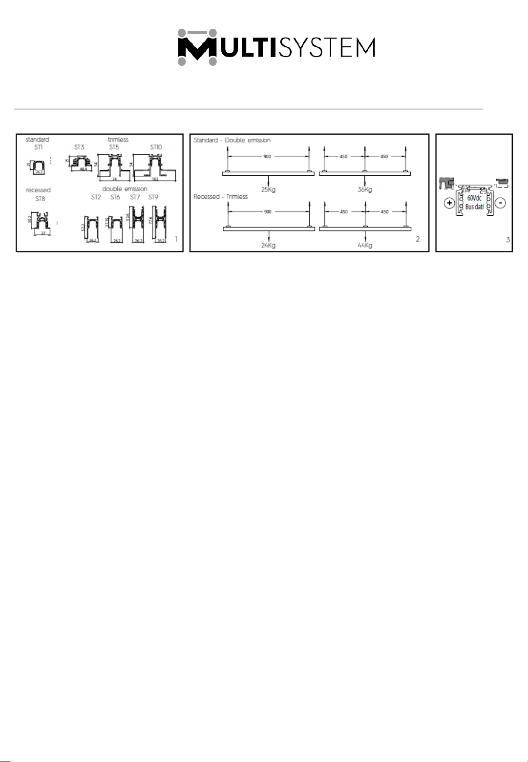
MULTISYSTEM Track:
www.lightingaustralia.com.au/products/lighting-track/multisystem-48v-track/multisystem-48v-track-accessories
Dimensions Max load Polarity
The MULTISYSTEM© track is a Class III – SELV product. The supply voltage must be between 0 and 60
VDC and the supply current must not exceed 15A. The operating temperature must not exceed 70°C.
The 4 track conductors can be used to create two separate power supply circuits, or one circuit for
the power supply and one for the DATA BUS. It is forbidden to use control gear, drivers, DATA BUS
systems and components that are not SELV-approved and/or with U-OUT greater than 60 VDC. If in an
installation the track system is being integrated with a larger lighting control system by electronically
merging the DATA BUS of the low-voltage track with that of other fittings, all components used must be
SELV-approved. Multiple track versions are available in order to create different light applications
(Fig.1.). Do not exceed the maximum loads specified (Fig.2.) When installing the fittings in false ceilings,
comply with the maximum load-bearing capacity of the relevant structure. All tracks come with a
mechanical key (Fig.3.); the electrical accessories are supplied in both polarised and non-polarised
versions. During assembly operations, respect the polarity only for the luminaires that require it.
Safety Warnings for products and installation
- The use of NON SELV or U-OUT > 60V dc power supplies, drivers and components is strictly forbidden.
A.A.G. Stucchi recommends the usage of an opto-insulated repeater dali compatible (eg. RP-DALI-
24-48V)
- You can choose to use the 4 conductors of the track in 2 different modes:
- 2 different power supplies (2 circuits, 0 – 60V dc)
- 1 circuit for 60V dc and 1 circuit for DATA BUS
If you want to create a unique DATA BUS in your lighting project (building, shop etc), e;ectrically
connecting the low voltage track DATA BUS with the DATA BUS of other lighting application, all the
components involved must be SELV approved.
It is strictly forbidden to use any kind of solvent, glue, oil, grease or cleaner in contact with
MUTLISYSTEM components. The company is not responsible for any damage caused by the use of the
materials mentioned above.
2 11/7/2019
Page 3
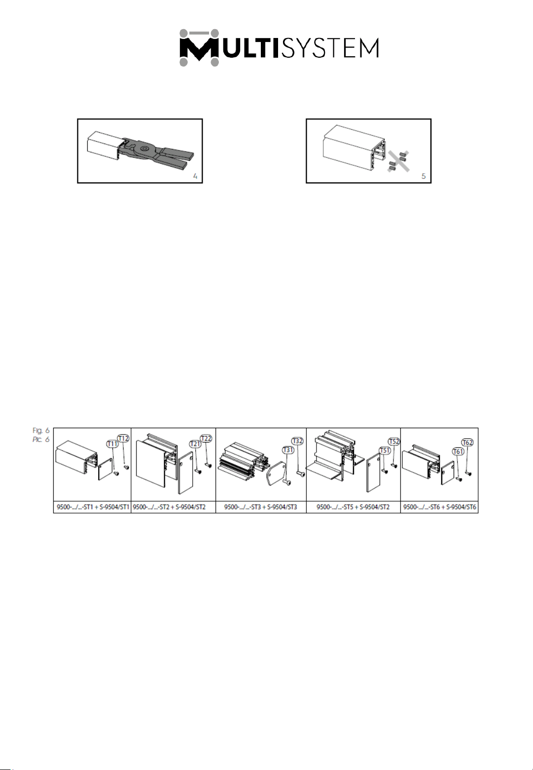
Recessing track conductors
Recessing
track
conductors
The track bars with 1-2-3 m length are supplied with the copper conductors already recessed at
each finished edge, to prevent them coming from into contact with one another in case of dual
power supply or, if end caps are used, to prevent the copper conductors from coming into contact
with them. If the track must be shortened during installation, after cutting it use the special pliers (S9000/T) to cut back the 4 copper conductors of the track (Fig.4.). Make sure to remove the 4 pieces
of copper conductor cut (Fig.5.). Proceed with the installation of another track or apply the end
caps as explained in the instruction sheet.
End Caps
3 11/7/2019
Page 4
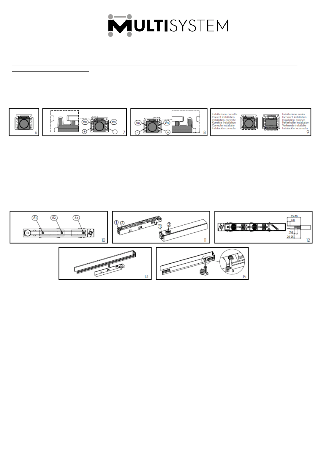
MULTISYSTEM End Feeds & Connections:
http://www.lightingaustralia.com.au/products/lighting-track/multisystem-48v-track/multisystem-48v-end-feedsconnection-joints-accessories
End Power Feed
There are two types of end power feeds: the non-polarised version (without mechanical key; codes
9501/… Fig.6) and the polarised version (with mechanical key on the left, code 9501-KL/… Fig.7 or on
the right, code 9501-KR/… Fig.8). If polarised end power feeds are used, it is important to respect the
wiring inside the item and to be very careful when inserting the end power feed into the track. Once
inserted with the key properly orientated, the end power feed must lie perfectly flush with the track
without protruding, and the key must not interfere with the track (Fig.9)
Use 4 x 1.5mm² cables to wire the end power feed. Remove the end power feed cover by loosening
the three screws A1-A2-A3 (Fig. 10) to access the electrical contacts. Apply force to removable
section 1 or 2 and feed the power cable through the resulting hole. Subsequently, depending on the
hole used, make a hole to pass the cable through the end cap or track (Fig.11). Remove the cable
sheaths and strip the cables (Fig.12), then wire the contacts of the end power feed taking care to
respect the markings on it (+/-). After completing the operations, use the screw-mount cable clamp
located on the power end feed, put the cover back on and tighten the three screws A1-A2-A3.
Lastly, insert the power end feed into the track (Fig.13) and secure it by means of device B fitted on
it, by turning until it stops (using an appropriate screwdriver, Fig. 14). The electrical connection to the
mains can only be achieved using items 9501…
4 11/7/2019
Page 5
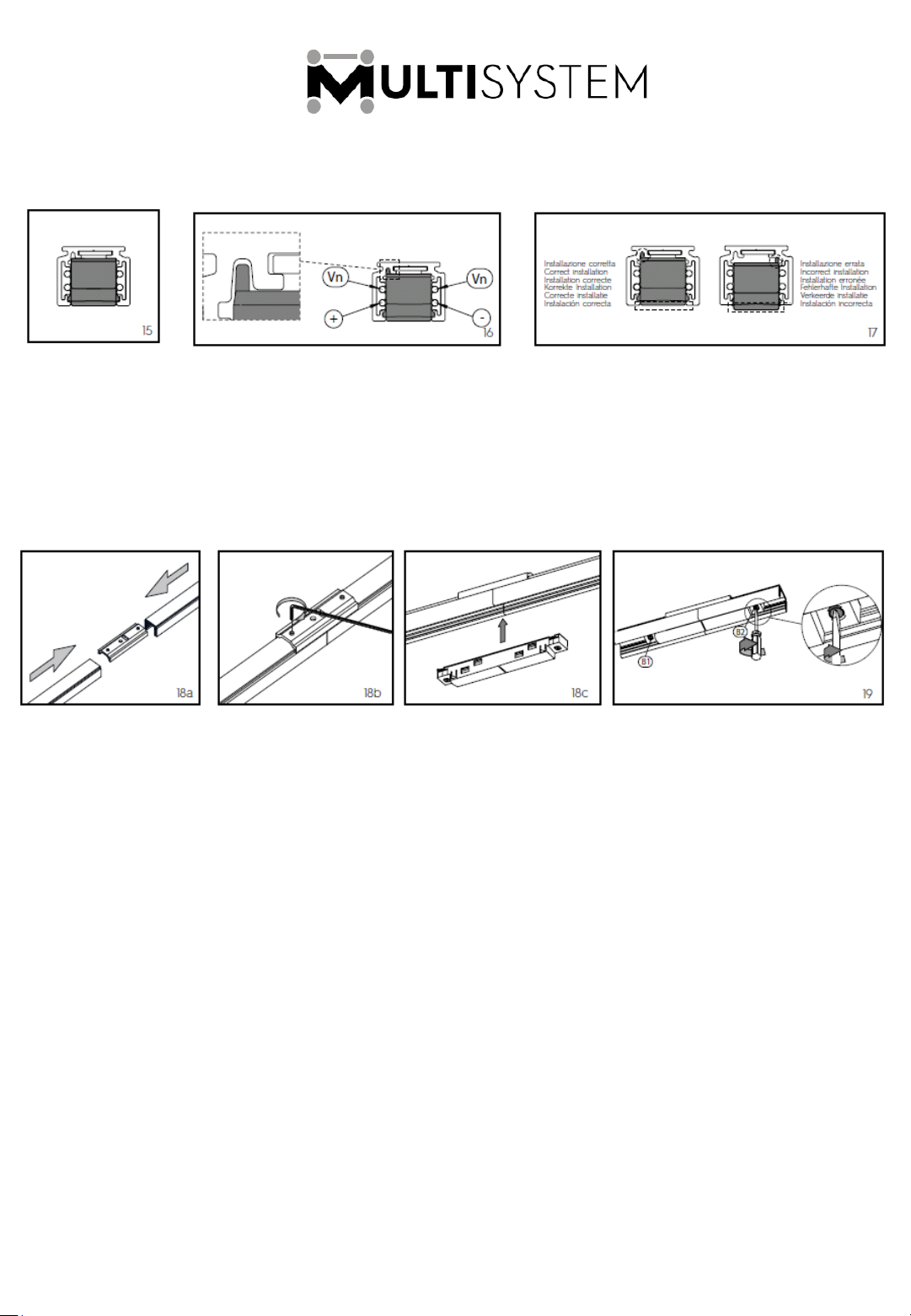
Linear Joint
There are two types of linear joints: the non-polarised version (without the mechanical key, code
9503-S/… Fig.15) and the polarised version (with mechanical key, code 9503-S-K/… Fig.16). If
polarised linear joints are used, take special care when inserting the joint into the track; once it has
been inserted with the key properly oriented, the joint must lie completely flush with the track
without protruding, and the key must not interfere with the track (Fig.17).
5 11/7/2019
Page 6
MULTISYSTEM Adapter (2A-60V dc; 10N):
www.lightingaustralia.com.au/products/lighting-track/multisystem-48v-track/multisystem-48v-adapters-andaccessories
Adapter
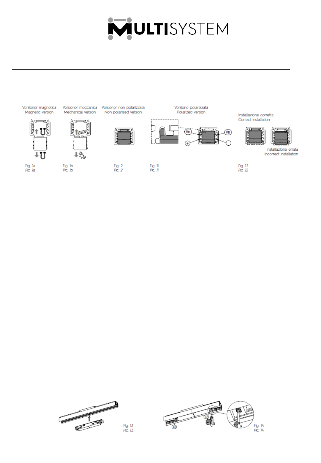
MULTISYSTEM adapters are available in two versions:
- Magnetic version adapters are equipped with permanent magnets which provide a connection to
the metal plate inside the track (Pic. 1).
- Mechanical version adapters with automatic lock (Pic 1b)
All MULTISYSTEM adapter series come in two versions; non-polarised (without mechanical key, codes
9519… and 9529… Pic. 2) and polarised (with mechanical key, codes 9519…-K… and 9529…-K… Pic.3).
When using polarised adapters, take special care when inserting the adapter into the track. Once
inserted with the key properly oriented, the adapter must fit perfectly flush with the track without
protruding, and the key must interfere with the track (Pic. 4)
To wire the adapter, use stranded and tinned cables with cross sectional area between 0.5mm² and
1mm² rated appropriately for the luminaire’s power to be connected to the adapter.
Remove the adapter cover by loosening the two screws C1-C2 (Pic. 6). Wire the cables to the adapter
(Pic. 7) using the appropriate tool (made up of S-9009/T-HANS+S-9009/T-INS, to be ordered separately)
can comply with the pole markings inside the adapter (Vn, +, -); push the cable in until it is completely
inserted in the IDC contact. After wiring the 4 contacts, feed the cables through the central hole F1 (if
items 9519…are used) or through the two side hole F2 and F3 (if series 9529… items are used) (Pic. 8).
The luminaire can be fastened to the adapter using the following accessories: S-9519/5 + S-9519/M8 or
S-9519/M10.
After wiring the fitting and fastening it to the adapter, put the cover on the adapter and tighten the
two screws C1 and C2 (when using polarised versions, make sure that the cove is mounted in the
proper direction).
Once mounted, the adapter cover must be perfectly level with the plane L, without bulging, so that it
does not interfere with the correct operation of the adapter once it is installed on the track (Pic. 8).
6 11/7/2019
Page 7
Adapter Rotation Kit and M10 or M8 Nipples
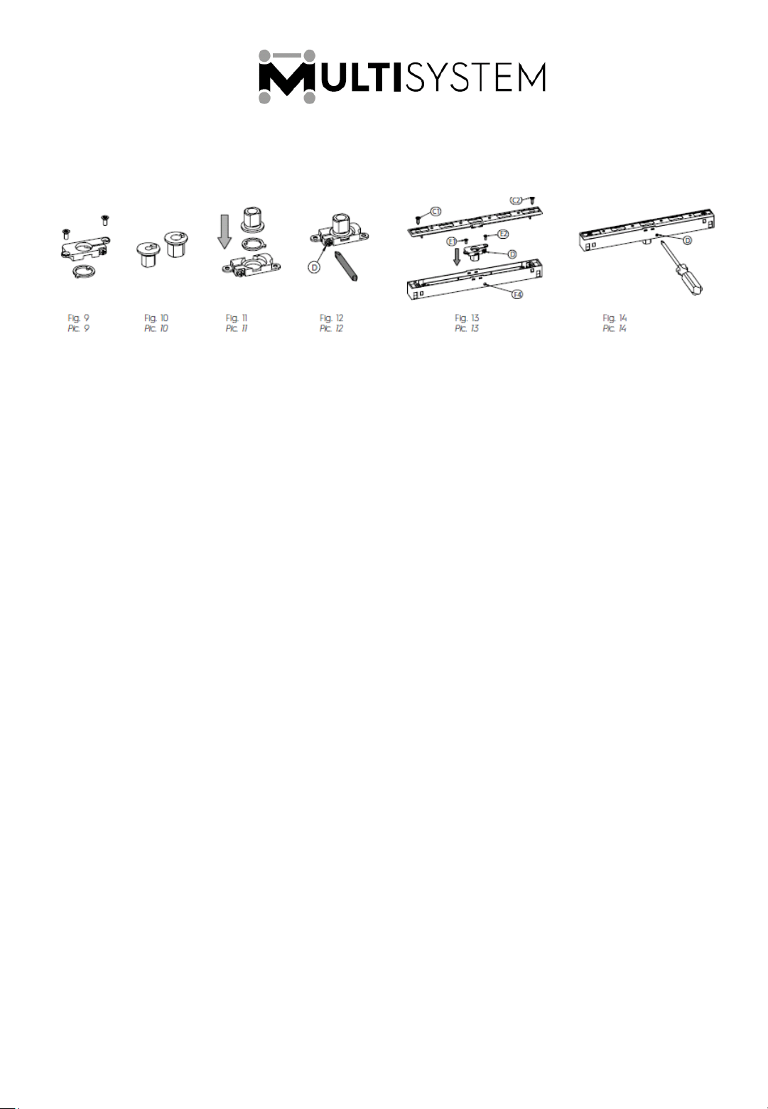
The luminaire can be fastened to the adapter using following accessories: S-9519/5 (Pic. 9) + S-
9519/M8 or S-9519/M10 (Pic. 10). If series 9529…M adapters are used, two rotation kits and two
nipple kits must be ordered. First place the special washer inside the plastic body of the
rotation kit, followed by S-9519/M10 or S-9519/M8 nipple (Pic. 11). Next, tighten screw B lightly
so that the washer and nipple are held in place inside their plastic housing (Pic. 12). Loosen
the two screws C1-C2 from the series 9519…M or 9529…M adapter and remove the cover;
insert the rotation kit, previously assembled with the washer and threaded nipple, by passing it
through the hole on the base of the adapter body. During assembly, screw D of the rotation kit
must be on the same side as hole F4 on the side wall of the adapter. Subsequently, screw the
rotation kit onto the adapter using the two screws E1-E2. After completing this operation, put
the cover on the adapter and tighten the two screws C1-C2 (Pic. 13) (when using polarised
versions, make sure that the cover is mounted in the proper direction). To increase or
decrease the friction of the adapter against the stem of the luminaire, tighten or loosen screw
D using an appropriate screwdriver (Pic. 14).
7 11/7/2019
Page 8
MULTISYSTEM Trimless Track Brackets:
www.lightingaustralia.com.au/products/lighting-track/multisystem-48v-track/multisystem-48v-track-mountingcomponents
Reinforcement Bracket for Trimless Tracks
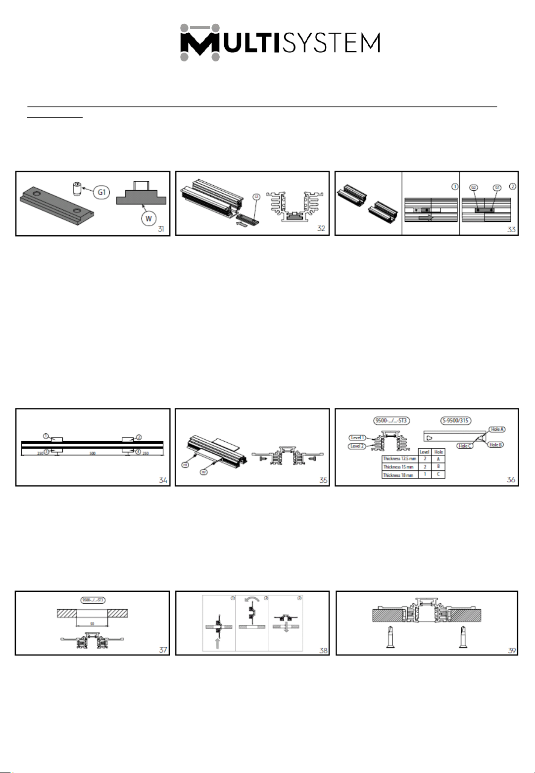
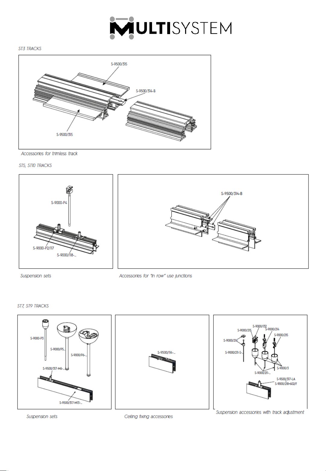
To fasten two sections of the trimless track, we recommend using bracket S-9500/314-B. Only screw
one of the set screws G1 onto the bracket, making sure that it does not protrude from the lower side
W of the bracket (Fig. 31). Slide the bracket into the first track section, from the side where set screw
G1 has not been inserted, and push it completely inside the track (Fig. 32). Take the second track
section and join it to the first section; slide the bracket (1) until it lies mid-way with respect to the two
sections (2), then insert the second set screw G2. Lastly, tighten both set screws G1 and G2 until the
bracket is tightly secured to the two track sections (Fig. 33).
For the electrical connections between the tracks use the pass-through joint 9503/…
Mounting Bracket for Trimless Tracks
To fasten trimless tracks (9500-…/…-ST3) to plasterboard, we recommend using bracket S-9500/315.
Use 4 brackets for every metre of track; 2 of them must be secured to each side and distributed
uniformly along the entire length of the track (Fig. 34), using the two screws H1 and H2 for each
bracket (Fig. 35). The track has two bracket mounting positions (Level 1 and Level 2), while the
bracket has 3 mounting holes (Hole 1, Hole 2 and Hole 3). Observing the various possible
combinations (Fig. 36), the track can be anchored to plasterboard with 3 different thicknesses:
12.5mm/ 15mm/ 18mm.
Once the 4 brackets have been fastened to the track, openings of suitable size must be cut into
the plasterboard (Fig. 37) then the track must be positioned above the plasterboard in the
manner illustrated (Fig. 38). Use appropriate screws (not supplied with the brackets) to fasten the
track to the plasterboard (Fig. 39). Before inserting the track into the plasterboard, mark on the
outside the position of the screws in relation to the track’s bracket.
8 11/7/2019
Page 9
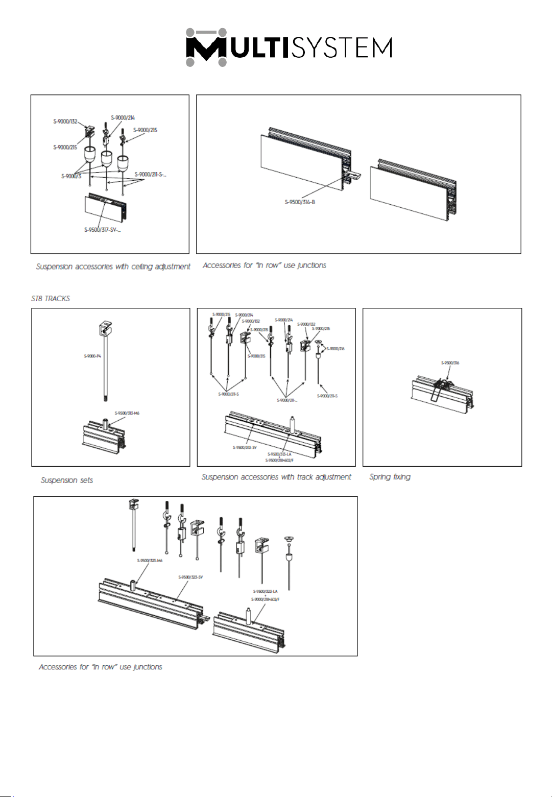
MULTISYSTEM Track Fixing Accessories:
www.lightingaustralia.com.au/products/lighting-track/multisystem-48v-track/multisystem-48v-trackmounting-components
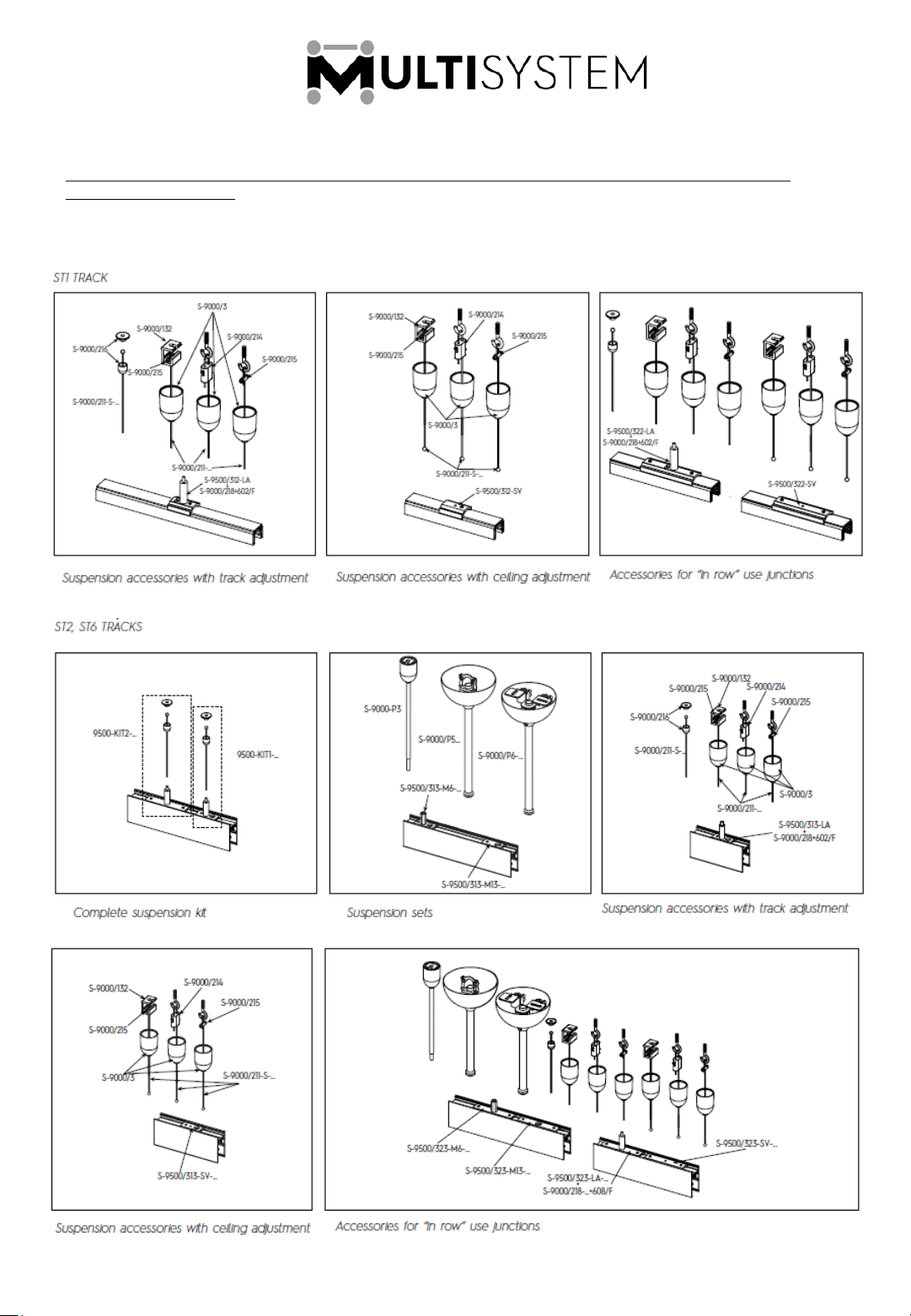
Assembly Diagrams
9 11/7/2019
Page 10
10 11/7/2019
Page 11
11 11/7/2019
 Loading...