

Page 1
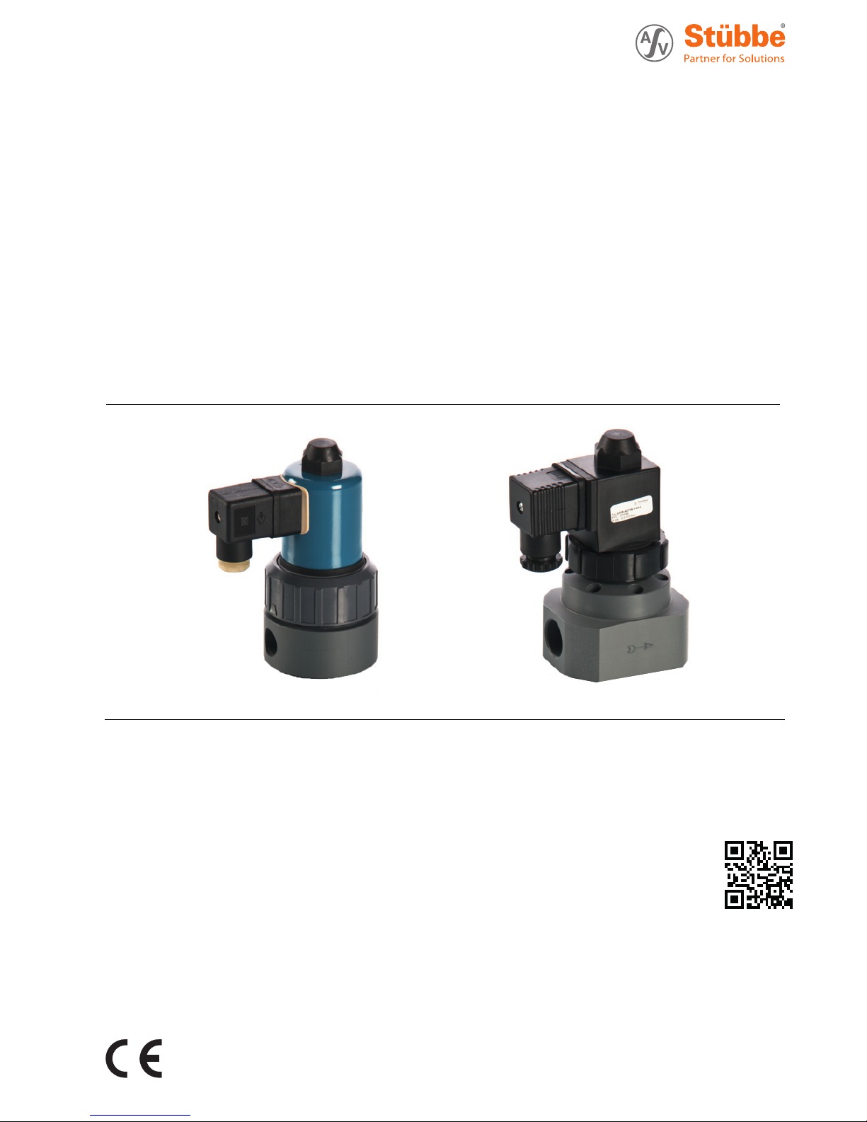
Solenoid valve
Operating manual Series
model 150
model 160
Version BA-2017.09.08 EN
Print-No. 301 215
TR MA DE Rev001
ASV Stübbe GmbH & Co. KG
Hollwieser Straße 5
32602 Vlotho
Germany
Phone: +49 (0) 5733-799-0
Fax: +49 (0) 5733-799-5000
E-mail: [email protected]
Internet: www.asv-stuebbe.com
We reserve the right to make
technical changes.
Read
carefully before use.
Save for future use.
Page 2

Table of contents
Table of contents
1 About this document ............................... 3
1.1 Target groups ............................... .. 3
1.2 Other applicable documents ......... ....... 3
1.3 Warnings and symbols ....................... 4
2 General safety instructions ....................... 5
2.1 Intended use ..................... ............. 5
2.2 General safety instructions .................. 5
2.2.1 Obligations of the operating company . . . .. . 5
2.2.2 Obligations of personnel ................. .... 5
2.3 Specific hazards ....... ....................... 5
2.3.1 Hazardous media ............... ............. 5
3 Layout and Function .. ............................. 6
3.1 Type plate ................................. .... 6
3.2 Description .................................... 6
3.3 Layout ......................................... 7
3.3.1 Type 150 .................................... .. 7
3.3.2 Type 160 .................................... .. 7
3.4 Direction of flow .............................. 8
4 Transport, Storage and Disposal ............... .. 8
4.1 Unpacking and inspection on delivery . . .. . . 8
4.2 Transportation ................................ 8
4.3 Storage ............................. .......... 8
4.4 Disposal ....................................... 9
5 Installation and connection ....................... 10
5.1 Preparing for installation ..................... 10
5.1.1 Check operating conditions ................. 10
5.2 Planning pipelines .. .......................... 10
5.2.1 Designing pipelines ...................... .... 10
5.3 Installing fitting in pipe ....................... 10
5.3.1 Fixed connection with solvent welding/fusion
spigot ends .................... ............... 10
5.3.2 Connection with internal thread fixed ..... .. 10
5.3.3 Insulate fitting .......................... ....... 11
5.4 Connect fitting to electrical system .. . .. .. .. 11
5.5 Performing the hydrostatic test .............. 11
6Operation . ........................................... 11
6.1 Commissioning ............................... 11
7 Maintenance .......................... ............... 12
7.1 Servicing ...................................... 12
7.2 Maintenance ................ .................. 12
7.2.1 Removing fitting ............ .................. 12
7.2.2 Changing magnetic coil of type 150 . . .. ... . 12
7.2.3 Changing magnetic coil of type 160 . . .. ... . 12
7.3 Replacement parts and return .............. 13
8 Troubleshooting ............................. ....... 14
9 Appendix ......................................... .... 15
9.1 Technical specifications ...................... 15
9.1.1 Working pressure .......................... .. 15
9.1.2 Pressure and temperature limits .. . .. .. . . .. 15
9.1.3 Tightening torques ....................... .... 15
9.2 Connection diagrams ........... ............. 15
9.2.1 Type 150 connection diagrams ............. 15
9.2.2 Type 160 connection diagrams ............. 15
9.3 Plug assignment ........................... .. 15
List of figures
Fig. 1 Type plate (example) ........... ............. 6
Fig. 2 Type 150 layout .................... .......... 7
Fig. 3 Type 160 layout .................... .......... 7
Fig. 4 Fitting with directional arrow (example) .. . .. 8
Fig. 5 Connection diagram (NO) (normally open),
type 150 ..................... .................. 15
Fig. 6 Connection diagram (NC) (normally closed),
type 150 ..................... .................. 15
Fig. 7 Connection diagram (NO) (normally open),
type 160 ..................... .................. 15
Fig. 8 Connection diagram (NC) (normally closed),
type 160 ..................... .................. 15
Fig. 9 connector plug ................................ 15
List of tables
Tab. 1 Other application documents, purpose and
where found ........................ .......... 3
Tab. 2 Warnings and symbols .......... ............. 4
Tab. 3 Troubleshooting .............................. 14
Tab. 4 Tightening torques ........................... 15
2 Type 150, Type 160 BA-2017.09.08 EN 301 215
Page 3
About this document
1 About this document
This manual
• ispartofthefitting
• applies to all series referred to
• describes safe and proper operation during all operating
phases
1.1 Target groups
Operating company
• Responsibilities:
– Keep this manual available at the place of operation,
also for future use.
– Ensure that employees read and observe this manual
and other applicable documents, especially the safety
instructions and warnings.
– Observe any additional country-specific rules and reg-
ulations that relate to the system.
Qualified personnel, fitter
• Mechanics qualification:
– Qualified employees with additional training for fitting
the respective pipework.
• Electrical qualification:
– Qualified electrician
• Responsibility:
– Read, observe and follow this manual and the other
applicable documents, especially all safety instructions
and warnings.
1.2 Other applicable documents
To download:
Resistance lists
Resistance of materials used to
chemicals
www.asv-stuebbe.de/pdf_resistance/300051.pdf
To download:
Type 150 data sheet
Technical specifications, conditions of
operation
www.asv-stuebbe.de/pdf_datasheets/301203.pdf
To download:
Type 160 data sheet
Technical specifications, conditions of
operation
www.asv-stuebbe.de/pdf_datasheets/301209.pdf
To download:
CE declaration of conformity
Conformity with standards
www.asv-stuebbe.de/pdf_DOC/301227.pdf
Tab. 1 Other application documents, purpose
and where found
301 215 BA-2017.09.08 EN Type 150, Type 160 3
Page 4
About this docum ent
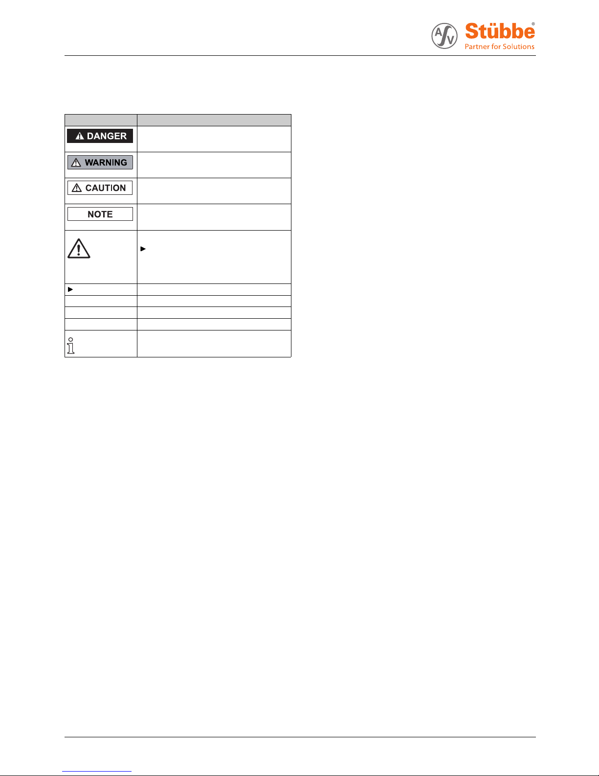
1.3 Warnings and symbols
Symbol
Meaning
• Immediate acute risk
• Death, serious bodily harm
• Potentially acute risk
• Death, serious bodily harm
• Potentially hazardous situation
• Minor injury
• Potentially hazardous situation
• Material damage
Safety warning sign
Take note of all information
highlighted by the safety warning
sign and follow the instructions to
avoid injury or death.
Instruction
1., 2., ... Multiple-step instructions
Precondition
→
Cross reference
Information, notes
Tab. 2 Warnings and symbols
4 Type 150, Type 160 BA-2017.09.08 EN 301 215
Page 5

General safety instructions
2 General safety instructions
The manufacturer accepts no liability for damages caused
by disregarding any of the documentation.
2.1 Intended use
•Onlyusethefitting to shut off pipes for appropriate media
(→ Resistance list).
• Adhere to the operating limits (→ Data sh eet)
•Usefitting only for solid-free media.
• Type 160: Difference of at least 0.3 bar required
2.2 General safety instructions
Read and observe the following regulations before carrying
out any work.
2.2.1 Obligations of the operating company
Safety-conscious operation
• Only operate the fittingifitisinperfecttechnical condition
and only use it as intended, staying aware of safety and
risks, and in adherence to the instructions in this manual.
• Ensure that the following safety aspects are observed and
monitored:
– Intended use
– Statutory or other safety and accident-prevention reg-
ulations
– Safety regulations governing the handling of haz-
ardous substances
– Applicable standards and guidelines in the country
where the pump is operated
• Make personal protective equ ipme nt available.
Qualified personnel
• Make sure all personnel tasked with work on the fitting have
read and understood this manual and all other applicable
documents, especially the safety, maintenance and repair
information, before they start any work.
• Organize r esponsibilities, areas of competence and the
supervision of personnel.
• The following work should be carried out by specialist technicians only:
– Installation, repair and maintenance work
– Work on the electrical system
• Make sure that trainee personnel only work on the fitting
under supervision of specialist technicians.
2.2.2 Obligations of personnel
• Observe the instruction s on the fitting and keep them legible, e.g. type plate, identification marking for fluid connections.
• Only carry out work on the fitting if the following requirements are met:
– System is empty
– System has been flushed
– System is depressurized
– System has cooled down
– System is secured against being switched back on
again
• Do not ma ke any modifications to the device.
2.3 Specifichazards
2.3.1 Hazardous media
• When handling hazardous media (e.g. hot, flammable,
explosive, toxic, hazardous to health or the environment),
observe the safety regulations for th e handling of hazardous substances.
• Use personal p rotective equipment when carrying out any
work on the fitting.
• Collect leaking pumped liquid and residues in a safe manner and dispose of in accordance with environmental regulations.
301 215 BA-2017.09.08 EN Type 150, Type 160 5
Page 6

Layout and Function
3 Layout and Function
3.1 Type plate
69224
150A0000/10/P1KME
0-2 bar
230 V 50 Hz
E173154
12 34567
8910
Fig. 1 Type plate (example)
1Type150/160
2IDnumber
3 Control function (A =NO/B =NC)
4 Nominal diameter [mm]
5 Materials (P1 = PVC / P2 =PP/P4 =PTFE)
6 Process connection (KM = adhesive socket end /
SM = fusion socket / G38 = threaded socket end 3/8
/ G12 = threaded socket end 1/2)
7 Elastomer (E = EPDM / F =FPM/T =PTFE)
8 Operating voltage / operating frequency
9 Serial number
10 Pressure range (dependent on nominal width in Type 150)
Device types
•Type150
•Type160
3.2 Description
The fitting is a solenoid valve. The fittingisusedforopening and closing conduits. The fittingcanbesuppliednormally
closed or normally open.
Type 150
The fitting is directly operated.
Type 160
The fitting is pilot operated. The fitting requires a differential
pressure between inlet and outlet of 0.3 bar for op ening and
closing.
Versions available:
•Type150
– Directly operated with PTFE rubber boot-sealed
plunger space
– DIN EN 175301-803 connector plug form A w ith built-in
rectifier
•Type160
– Pilot operated
– Sealed plunger space
– DIN EN 175301-803 connector plug form A without rec-
tifier
• Mounting position:
– Magnetic coil preferably upwards
– Install valve horizontally or vertically in conduit
• Valve functions:
– closed when de-energized (NC)
– open when de-energized (NO)
• Direction of flow as per direction of arrow on valve body
(→ 3.4 Direction of flow, Page 8 ).
6 Type 150, Type 160 BA-2017.09.08 EN 301 215
Page 7

Layout and Function
3.3 Layout
3.3.1 Type 150
10
11
12
13
14
15
16
17
9
8
7
6
5
4
3
2
1
Fig. 2 Type 150 layout
1 valve body
2 bellows
3 intermediate element
4 union nut
5 intermediate ring
6 plunger
7 plunger guide tube
8 magnet coil
9capnut
10 gasket
11 pressure spring
12 O-ring
13 flat sealing ring
14 O-ring
15 threaded bush
16 O-ring
17 seal bonnet
3.3.2 Type 160
14
13
12
11
10
9
8
7
6
5
4
3
2
1
15 16 17 18
Fig. 3 Type 160 layout
1 valve body
2 membrane
3cover
4 screw
5 pilot diaphragm
6 pressure disc
7 lift limitation
8 union nut
9 flat sealing ring
10 plunger
11 pre
ssure spring
12 plunger guide tube
13 O-ring
14 oil
screw
15 cap nut
16 gasket
17 magnet coil
18 connector plug
301 215 BA-2017.09.08 EN Type 150, Type 160 7
Page 8

Transport, Storage and Disposal
3.4 Direction of flow
The direction of flow can be identified by the arrow on the
fitting.
1
Fig. 4 Fitting with directional arrow (example)
1 Directional arrow
4 Transport, Storage and
Disposal
4.1 Unpacking and inspection on delivery
1. Unpack the fitting when received a nd inspect it for transport
damage.
2. Report any transport damage to the manufacturer immediately.
3. Ensu re that the information on the type plate agrees with
the order/design data.
4. For immediate installation, dispose of packaging material
according to local regulations.
– For later installation, leave the fitting in the original
packaging.
4.2 Transportation
1. If possible, transport fitting (including drive) in original packaging.
2. Lift fitting manually for transport. For weight specifications
(→ data sheet).
4.3 Storage
NOTE
Material damage due to inappropriate storage!
Store the fitting properly.
Make sure the storage room meets the following conditions:
–Dry
– Frost-free
– Vibration-free
– Not in direct sunlight
– Storage temperature +10 °C to +60 °C
8 Type 150, Type 160 BA-2017.09.08 EN 301 215
Page 9

Transport, Storage and Disposal
4.4 Disposal
Plastic parts can be contaminated by poisonous or radioactive media to such an extent that clea ning will not be suffi-
cient.
WARNING
Risk of poisoning and environmental damage from
medium.
Use personal p rotective equipment when carrying out any
work on the fitting.
Before disposing of the fitting:
– Collect escaping medium and dispose separately
according to local regulations.
– Neutralize residues of medium in th e fitting.
Remove plastic parts and dispose of them in accordance
with local regulations.
Dispose of fitting in accordance with local regulations.
301 215 BA-2017.09.08 EN Type 150, Type 160 9
Page 10

Installation and connection
5 Installation and connection
5.1 Preparing for installation
5.1.1 Check operating conditions
1. Ensure the design of the fitting is consistent with the purpose intended:
– Materials used (→ type plate).
–Medium(→ order and design data).
2. Ensu re the required operating conditions are met:
– Resistance of body and seal material to the medium
(→ resistance lists).
– Media temperature (→ Data sheet).
– Operating pressure (→ Data sheet).
3. Con s ult with the manufacturer regarding any other use of
the device.
5.2 Planning pipelines
5.2.1 Designing pipelines
WARNING
Risk of pois oning and e nvironmental damage from
medium.
Leaks due to impermissible pipework forces.
Ensure that the fitting is n ot subject to any pulling o r thrusting forces or bending moments.
1. Plan pipes safely:
– No pulling or thrusting forces
– No bending moments
– Adjust for changes in length due to temperature
changes (compensators, expansion shanks)
– Observe direction of flow
– Observe installation position and installation direction
of the fitting
2. Dimensions (→ Data sheet).
3. Provide dirt arresters for trouble-free operation.
5.3 Installing fittinginpipe
WARNING
Risk of pois oning and e nvironmental damage from
medium.
Leak due to faulty installation.
Installation work on the pipes should only be performed
by technicians who have been specially trained for the
pipework in question.
NOTE
Material damage from incorrect installation of fitting!
Install fitting vertically or horizontally.
Install fitting with the magnetic coil preferably aligned
upwards.
NOTE
Material damage due to contamination of the fitting!
Make sure no contamination reaches the fitting.
Flush the pipe with a neutral medium.
The fittingisinstalledaccordingtotheconnectiontypeof
the pipes.
For connection with solvent welding/fusion spigot ends:
Use suitable solvent welding/fusion socket e nds.
Observe direction of flow (→ 3.4 Direction of flow,
Page 8 ).
5.3.1 Fixed connection with solvent welding/fusion
spigot ends
1. Prepa re pipe ends according to connection type.
2. Align fitting with the magnetic coil preferably upwards.
3. Adh esively apply or weld fitting with solvent welding/fusion
socket ends.
5.3.2 Connection with internal thread fixed
1. Prepa re pipe ends according to connection type.
2. Align fitting with the magnetic coil preferably upwards.
3. Screw pipe ends with fitting.
10 Type 150, Type 160 BA-2017.09.08 EN 301 215
Page 11

Operation
5.3.3 Insulate fitting
Fittingisinstalledinpipe
The fitting housing can be insulated to avoid mediumrelated temperature differences.
Insulate fitting housing as needed. In doing so, ensure the
following:
– Magnetic coil is free in order to avoid heat accumula-
tion.
– Use suitable insulation material for fitting housing.
5.4 Connect fitting to electrical system
Power supply switched off and secured against being
switched back on again.
DANGER
Risk of electrocution!
All electrical work m ust be carried out by qualified electricians only.
Switch off system power supply and secure it against being
switched back on again.
NOTE
Danger of overheating from wrong plug!
Mount only rectifier connectors on Type 150.
1. Ensure correct current type and voltage before electrical
connection (→ data sheet).
2. Ensure that the plug connection is protected against permanent dampness. Provide cover as need ed.
3. Connecting cable to connector
(→ 9.3 Plug assignment, Page 15).
4. Insert connector into connector socket of the fitting.
5.5 Performing the hydrostatic test
Pressure test usi ng neutral medium, e.g. water.
1. Pressurize the fitting, ensuring
– Test pressure < permissible system pressure
– Test pressure < 1.5 PN
– Test pressure < PN + 5 bar
2. Check the fitting for leaks.
6 Operation
6.1 Commissioning
Fitting correctly installed and connected
WARNING
Risk of injury and poisoning due to medium spraying out.
Use personal p rotective equipment when carrying out any
work on the fitting.
NOTE
AC magnets can be destroyed by o verheating!
When commissioning the fitting with AC magnet, ensure
that the magnetic coil is mounted on the plunger guide tube.
1. For the type 160 ensure that there is a differential pressure
of at least 0.3 bar between valve inlet and valve outlet.
2. After the first loads from pressure and operating temperature, check that the fitting is not leaking.
301 215 BA-2017.09.08 EN Type 150, Type 160 11
Page 12

Maintenance
7 Maintenance
WARNING
Risk of injury and poisoning due to hazardous media liquids!
Use personal protective equipment when carrying out any
work on the fitting.
7.1 Servicing
1. Visual and function check (every three months):
– Normal operating conditions unchanged
–Noleaks
– No unusual operating noises or vibrations
2. Cle an fittin g with a moist cloth if necessary.
7.2 Maintenance
DANGER
Risk of electrocution!
All electrical work must be carried out by qualified electricians only.
WARNING
Risk of injury and poisoning due to hazardous or hot
media.
Use personal protective equipment when carrying out any
work on the fitting.
Safely collect the media and dispose of it in accordance
with environmental regulations.
WARNING
Risk of injury during disassembly!
Wear protective gloves, components can be very sharpedged due to wear or damage.
Remove components with springs (e.g. pneumatic drive)
carefully, since spring tension can cause components to
be ejected.
7.2.1 Removing fitting
1. Ensu re that:
– System is empty
– System has been flushed
– System is depressurized
– System has cooled down
– System is secured against being switched back on
again
2. Remove fitting from the pipe.
3. Decontami nate fitting if required.
–Deadspaceinthefitting may still contain medium.
7.2.2 Changing m agnetic coil o f type 150
System is switched off and secured against being switched
back on again
Follow the section drawing for disassembly (→ 3.3.1 Type
150, Page 7 ).
1. Remove connector from fitting.
2. Unscrew cap nut (9).
3. Remove gasket (10). Dispose of defective gasket.
4. Remove magnetic coil (8). Dispose of defective ma gnetic
coil.
5. In stall new magnetic coil (8).
6. Moun t gasket (10).
7. Tighten cap nut (9) (→ 9.1.3 Tightening torques, Page 15).
8. Connect fitting to electrical system (→ 5.4 Connect fitting
to electrical system, Page 11).
9. Performing the hydrostatic test (→ 5.5 Performing the
hydrostatic test, Page 11).
7.2.3 Changing m agnetic coil o f type 160
System is switched off and secured against being switched
back on again
Follow the section drawing for disassembly (→ 3.3.2 Type
160, Page 7 ).
1. Remove connector from fitting.
2. Unscrew cap nut (15).
3. Remove gasket (16). Dispose of defective gasket.
4. Remove magnetic coil (17). Dispose of defective magnetic
coil.
5. Install new magnetic coil (17).
6. Moun t gasket (16).
7. Tighten cap nut (15) (→ 9.1.3 Tightening torques,
Page 15).
8. Connect fitting to electrical system (→ 5.4 Connect fitting
to electrical system, Page 11).
9. Performing the hydrostatic test (→ 5.5 Performing the
hydrostatic test, Page 11).
12 Type 150, Type 160 BA-2017.09.08 EN 301 215
Page 13

Maintenance
7.3 Replacement parts and retu rn
1. Have the following information ready to hand when ordering spare parts (→ type plate).
– Fitting type
– ID number
– Nominal pressure and diameter
– Body and seal material
2. Please complete and enclose the document of compliance
for returns
(→ www.asv-stuebbe.com/service/downloads).
3. Only use spare parts from ASV Stübbe.
301 215 BA-2017.09.08 EN Type 150, Type 160 13
Page 14

Troubleshooting
8 Troubleshooting
WARNING
Risk of injury and poisoning due to hazardous or hot
media.
Use personal protective equipment when carrying out any
work on the fitting.
Safely collect the media and dispose of it in accordance
with environmental regulations.
Consult with the manufacturer regarding faults which are not
identified in the following table, or which cannot be traced to
the indicated causes.
Error Possible cause
1
Corrective action
Rated voltage is still present
Check control voltage.
Incorrectly installed
Install fitting in accordance with direction of flow.
When doing so follow arrow m arking on fitting
(→ 3.4 Direction of flow, Page 8 ).
Differential pressure between
valve input and valve outlet too
low
2
Ensure th at there is a differential pressure of at least 0.3 bar
between valve inlet and valve outlet.
Valve does not close
Plunger disabled
Change fitting.
Operating pressure too high Check operating pressure and adjust permissible operating
pressure if necessary (→ data sheet).
Connection voltage is cut or
insufficient
Check supply voltage.
Check cable connection and if necessary cable correctly.
Rated voltage and coil voltage
different
Ensure that the fitting is suitable for the intended use.
Check specifications of the fitting (→ data sheet).
Magnetic coil defective Type 150: Install new magnetic coil (→ 7.2.2 Changing
magnetic coil of type 150, Page 12).
Type 160: Install new magnetic coil (→ 7.2.3 Changing
magnetic coil of type 160, Page 12).
Rectifier defective
3
Fit new rectifier connector (→ 5.4 Connect fitting to
electrical system, Page 11).
Valve does not open
Plunger disabled
Change fitting.
Medium escaping at pipe
connection
Pipe connection leaking
Check pipe connection at the fitting and tighten if necessary.
Use new seal as needed.
Tab. 3 Troubleshooting
1) Faults apply for stand ard valve (NC) normally closed
2) applies to Type 160
3) applies to Type 150
14 Type 150, Type 160 BA-2017.09.08 EN 301 215
Page 15

Appendix
9 Appendix
9.1 Technical specifications
Technical data (→ Data sheet).
9.1.1 Working pressure
Operating pressure (→ Data sheet).
9.1.2 Pressure and temperature limits
Pressure and temperature limits (→ data sheet).
9.1.3 Tightening torques
Description
Size
Tightening torque
Cap nut SW 24
hand-tight
Tab. 4 Tightening torques
9.2 Connection diagrams
9.2.1 Type 150 connection diagrams
A
P
Fig. 5 Connection diagram (NO) (normally open), type 150
A
P
Fig. 6 Connection diagram (NC) (n ormally
closed), type 150
9.2.2 Type 160 connection diagrams
A
P
Fig. 7 Connection diagram (NO) (normally open), type 160
A
P
Fig. 8 Connection diagram (NC) (n ormally
closed), type 160
9.3 Plug assignment
DIN EN 175301-803 plug socket. The polarity of the connections (1,3) has no effect on operation.
1
2
3
Fig. 9 connector plug
1 control voltage
2earth
3 control voltage
301 215 BA-2017.09.08 EN Type 150, Type 160 15
Page 16

Appendix
16 Type 150, Type 160 BA-2017.09.08 EN 301 215
 Loading...