

Stuart Turner Submersible Supersub VA User Manual
Submersible Pumps
OPERATING INSTRUCTIONS
Please leave this instruction booklet with the pump as it
contains maintenance and safety information
(Original Instructions)
SUBMERSIBLE MODELS
Supersub 150VA
Supersub 250VA
INDEX . . . . . . . . . . . . . . . . . . . . . . . . . . . . . . . . . . . . . . . . . . . . . . . . Page No
Application . . . . . . . . . . . . . . . . . . . . . . . . . . . . . . . . . . . . . . . . . . . . . . . . . . . . . . . . . . . . . . . . 2
Product Description . . . . . . . . . . . . . . . . . . . . . . . . . . . . . . . . . . . . . . . . . . . . . . . . . . . . . . . . . 3
Limits of Application . . . . . . . . . . . . . . . . . . . . . . . . . . . . . . . . . . . . . . . . . . . . . . . . . . . . . . . . . 3
Technical Specication . . . . . . . . . . . . . . . . . . . . . . . . . . . . . . . . . . . . . . . . . . . . . . . . . . . . . . 4
Connections. . . . . . . . . . . . . . . . . . . . . . . . . . . . . . . . . . . . . . . . . . . . . . . . . . . . . . . . . . . . . . . 4
Siting of the Pump . . . . . . . . . . . . . . . . . . . . . . . . . . . . . . . . . . . . . . . . . . . . . . . . . . . . . . . . . . 5
Float Switch . . . . . . . . . . . . . . . . . . . . . . . . . . . . . . . . . . . . . . . . . . . . . . . . . . . . . . . . . . . . . . . 5
Pipework . . . . . . . . . . . . . . . . . . . . . . . . . . . . . . . . . . . . . . . . . . . . . . . . . . . . . . . . . . . . . . . . . 7
Electrical Installation . . . . . . . . . . . . . . . . . . . . . . . . . . . . . . . . . . . . . . . . . . . . . . . . . . . . . . . . 7
Noise . . . . . . . . . . . . . . . . . . . . . . . . . . . . . . . . . . . . . . . . . . . . . . . . . . . . . . . . . . . . . . . . . . . . 9
Commissioning . . . . . . . . . . . . . . . . . . . . . . . . . . . . . . . . . . . . . . . . . . . . . . . . . . . . . . . . . . . . 9
Maintenance . . . . . . . . . . . . . . . . . . . . . . . . . . . . . . . . . . . . . . . . . . . . . . . . . . . . . . . . . . . . . . 10
Trouble Shooting Guide . . . . . . . . . . . . . . . . . . . . . . . . . . . . . . . . . . . . . . . . . . . . . . . . . . . . . . 12
Environment Protection . . . . . . . . . . . . . . . . . . . . . . . . . . . . . . . . . . . . . . . . . . . . . . . . . . . . . 12
IMPORTANT NOTES
z Please read these instructions fully before starting the
installation:
z The installation must comply with the relevant water supply,
electrical and building regulations and be installed by a
competent person.
z If in doubt, consult Stuart Turner Ltd.
APPLICATION
General
z The pumps must not be used with salt water, sewage, flammable,
corrosive or explosive liquids (eg. petroleum oil, petrol, thinners)
grease, oils or foodstuffs.
z This appliance is not intended for use by persons (including children)
with reduced physical, sensory or mental capabilities, or lack of
experience and knowledge, unless they have been given supervision
or instruction concerning use of the appliance by a person responsible
for their safety.
z Children should be supervised to ensure that they do not play with the
appliance.
The submersible pump range is designed for re-circulation, drainage and transfer of
fresh water in outdoor or indoor applications.
The pumps incorporate an integral float switch, which provides automatic pump control in
the form of a low level cut out to prevent the risk of dry running.
- 2 -

The pumps are suitable for dirty water applications and are capable of handling semi-
solids in suspension of up to *5 mm in diameter.
*Note: Applicable only when pump is suspended above bottom of sump. When pump is
located on the bottom of sump the inlet grille will restrict solid ingress diameters to
3 mm.
WARNING AGAINST MISUSE
This pump set must not be used for any other application without the
written consent of Stuart Turner Limited and in particular, must not be
connected directly to the mains water supply or used outside the
conditions specified in the limits of application.
PRODUCT DESCRIPTION
Electric motor driven submersible pump with float switch control.
Motor
All motors are induction type, permanent capacitor, fitted with integral auto-resetting
thermal overload protection, IPX8 enclosure, class ‘B’ insulation and continuously rated.
The motor is encapsulated in a casing and protected from water ingress by two separate
lip seals running on a shaft sleeve, lubricated with a biodegradable vegetable oil.
Pump
All models are close coupled to the motor and are of centrifugal design and are supplied
as standard with a 90o elbow and stepped hose connector.
Supersub are single stage units and are supplied pre-fitted with a 10 metre mains supply
cord.
Standard pump materials of construction of major wetted parts are as follows.
Model Body Impeller Shaft
All
Glass filled
Polypropylene
Polyamide Coated Steel
Motor
Encapsulent
Stainless Steel/
Cast Aluminium
Seal
(Lip)
Nitrile
Float Switch
Factory fitted assembly for automatic pump control, provided with a manual override.
The wetted materials of construction are glass filled polypropylene, ABS Polyamide and
Acetal.
LIMITS OF APPLICATION
Max.
Model
Supersub 150VA 35 4 7 fully submerged 30 6.5
Supersub 250VA 35 4 7 fully submerged 30 8.5
Water
Temp.
o
C
Min.
Water
Temp.
o
C
Max.
Immersion
Depth
(m)
- 3 -
Min.
Immersion
Depth
(mm)
(for cont. operation)
Max.
No.
Starts/h
Max.
Head (pump
closed valve)
(m)
TECHNICAL SPECIFICATION
Model
Supersub 150VA 230/1/50 275 180 1.2 IPX8 Continuous 260 158 320 4.6 1
Supersub 250VA
Supply
230/1/50 508 350 2.2 IPX8 Continuous 260 158 320 4.8 1
Max. Watts
Consumed
Nominal
Watts
Output
(Motor)
Stuart Turner reserve the right to amend the specification in line with its policy of
continuous development of its products.
Note: For information on other voltages/frequencies which are not shown, consult any
supplementary instruction sheet supplied, or the rating label attached to the
pump.
Full
Load
Current
(AMPS)
H
Enc.
Rating
Duty
Rating
Dims (mm)
L W H
Gross
Weight
(packed)
kg
No. of
Pump
Stages
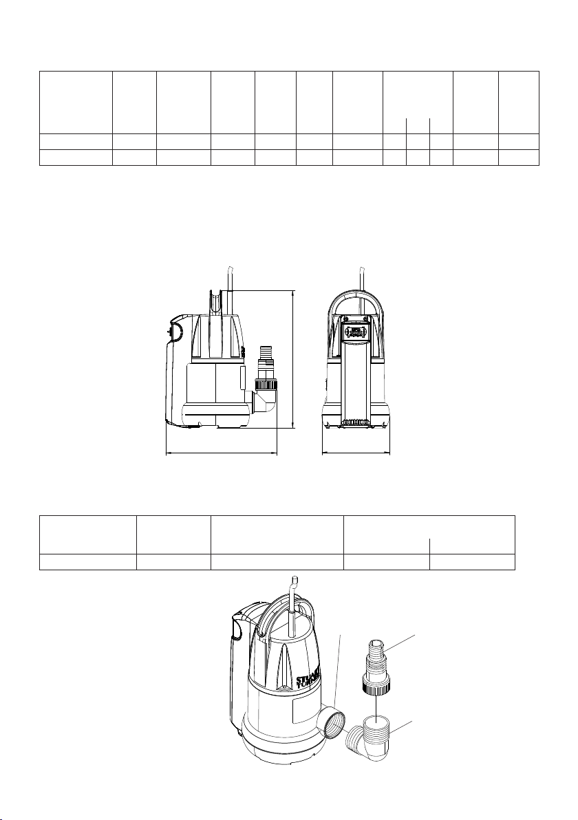
L
W
Fig. 1 (Dimension Key)
CONNECTIONS
Supersub pumps are supplied with an elbow and stepped hose connector which can be
screwed to the pump outlet port.
Pump Type
Supersub G1½ F G1½ M x G1½ M x 90
Pump
Outlet
Fig. 2
Elbow Hose Connector
o
Thread Hose Bore (mm)
G1½ / G1 F 30 / 25
Pump Outlet
Port
Stepped Hose
Connector
90o Elbow
- 4 -
SITING OF THE PUMP
WARNINGS:
z Do not run against a closed valve for periods longer than 5 minutes.
z The water in and around the pump must not be allowed to freeze. This
will result in pump damage.
z Do not under any circumstances use the supply cord fitted, as a
means to carry or lower the pump into position on installation. Attach
a rope sling to handle.
z Do not allow plastic pump parts to come into contact with solder flux,
oil or cellulose based paints, paint thinners or strippers, acid based
descalents or aggressive cleaning agents.
z When siting the pump ensure its base is raised slightly from the
bottom of the sump reducing the possibility of blocking the filter with
debris or drawing in small stones.
General
The pump must be installed in the vertical position and must be fully submerged at all
times when operating continuously to avoid overheating of the motor. However, when the
automatic float switch option is selected, the pump may be operated partially submerged
for short periods (see float switch operation section for further details).
When siting the pumps in a location where organic or general debris is likely, ensure the
pump is placed on its base on a flat horizontal surface (eg. on a paving slab) to enable full
functionality of the inlet filter grille and to prevent the force of the pump from drawing in
small stones. This will result in pump damage.
FLOAT SWITCH
The pumps incorporate an integral automatic float switch which has two modes of
operation, auto and manual.
The float switch consists of a float which moves up and down on a vertical axis within a
housing.
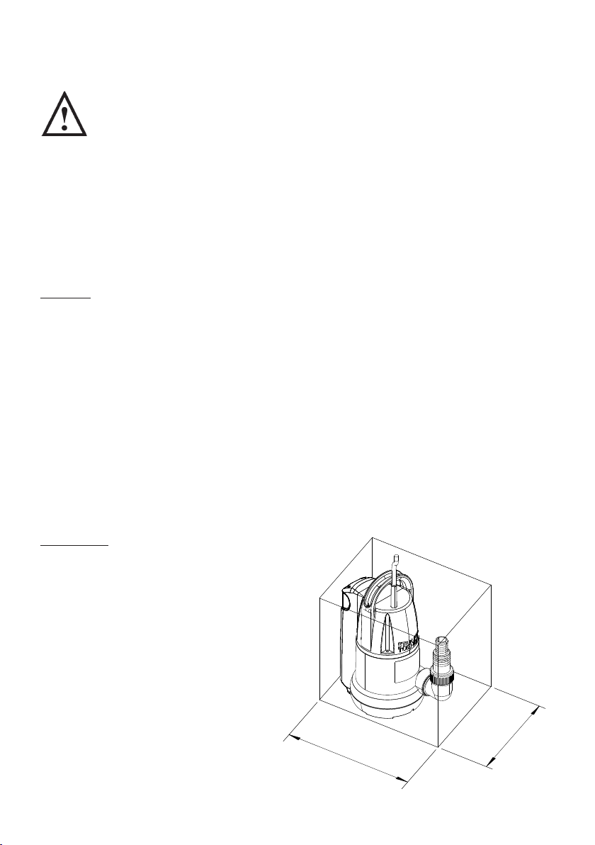
Sump Size
The minimum possible sump size is
270 mm x 170 mm.
Fig. 3
- 5 -
70
2
70
1
 Loading...