


Supplementary Instruction Sheet
- Boostamatic Diver Pumps -
The following information is to be read in conjunction with operation booklets, supplied
with the pump and control module.
IMPORTANT NOTES
Please read these instructions fully before starting the
installation.
The installation must comply with the relevant water supply,
electrical and building regulations and be installed by a
competent person.
If in doubt, consult Stuart Turner Ltd.
Further information can be found in the individual Diver and
Control Module instruction books.
APPLICATION
The Boostamatic Diver range is designed for pressure boosting applications in clean
fresh water systems, where under gravity, no flow is available.
WARNING AGAINST MISUSE
This pump set must not be used for any other application without the
written consent of Stuart Turner Limited and, in particular, must
not be connected directly to the mains water supply or used outside the
conditions specified in the limits of application.
This appliance is not intended for use by persons (including children)
with reduced physical, sensory or mental capabilities, or lack of
experience and knowledge, unless they have been given supervision
or instruction concerning use of the appliance by a person responsible
for their safety.
Children should be supervised to ensure that they do not play with the
appliance.
PRODUCT DESCRIPTION
Control Module
All models use the solid state IP65 rated pressure control module, mounted remotely
with the Diver units. The wetted materials of construction are brass, rubber and nylon 66.
- 1 -
Cont ...
SITING OF THE PUMP/PIPEWORK
WARNINGS:
Ensure pipework from pump is independently supported to prevent
forces being transferred to outlet branch.
Do not under any circumstances use the cable fitted as a means to
carry or lower the pump into position on installation. Attach a rope
sling to the lifting eye.
Ensure the pump or controller cannot be subjected to freezing
conditions as damage may result.
Never run pump whilst sucking air/liquid as the motor will overheat. To
prevent this from happening always install pump in the vertical position
and ensure fully submerged.
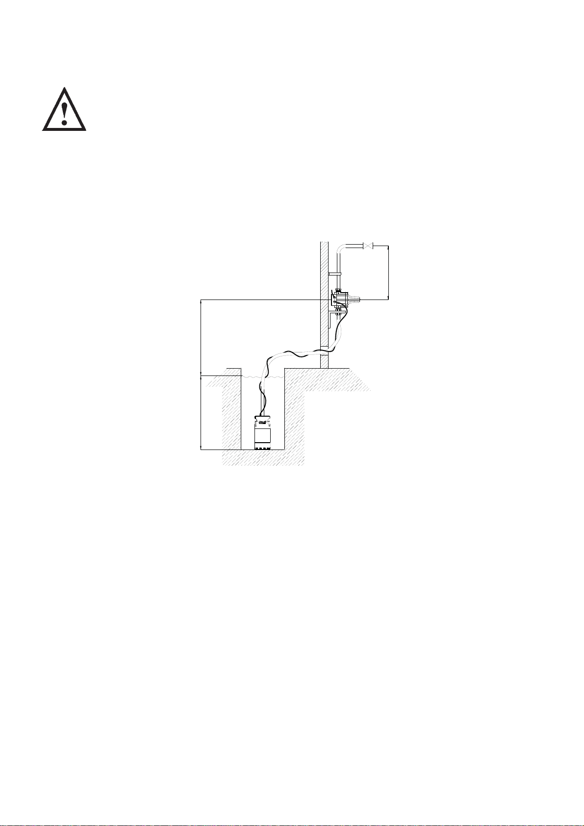
Typical Submersible
Boostamatic Installation
Fig. 1
The pumps are supplied with a non-return valve which should be screwed into the pump
outlet port using the supplied adaptor (Fig. 2). The purpose of the valve is to limit back flow
and pressure on the pump and ensure discharge pipework is always primed with water.
The pumps are also supplied with an outlet adaptor which allows for a 25 mm diameter
bore hose. The pump should be installed vertically and should be submerged at all times
to avoid overheating of the motor. When siting the pump ensure its base is raised slightly
from the base of the sump reducing the possibility of blocking the pump inlet filter with
debris. The discharge pipework must be independently supported to prevent forces being
transferred to pump outlet branch.
If the pump is not to sit on the bottom of the sump or it is too deep, then it should be
suspended by a rope attached to the lifting eye located on top of the pump.
All connections are to be as shown in Fig. 2 (ensure all joints are watertight). The control
module is to be mounted remotely from the pump in a dry frost free enclosure or building
(Fig. 1). Ensure the water flow is in the direction of the arrows that are moulded onto the
pressure control module (vertically upwards).
The control module must be mounted in the vertical position and not mounted in any
other way (on its side for instance).
The pump must be wired to the control module as detailed in wiring diagram section.
- 2 -
Cont ...
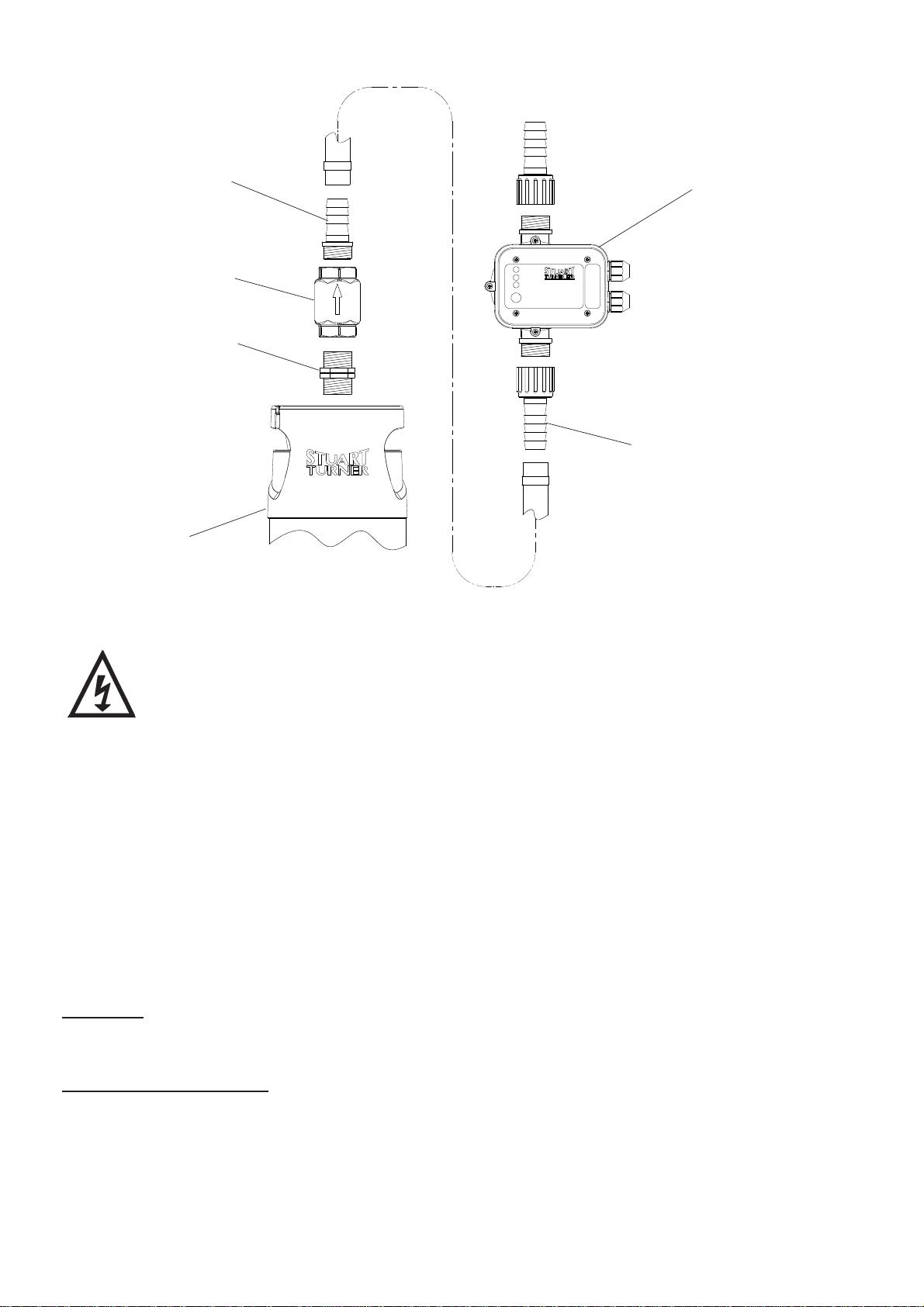
Hose adaptor
(with pump)
Non-return valve
(note direction arrow)
G 1 nipple
Diver pump
Fig. 2
Control module
Hose adaptor
(with control module)
ELECTRICAL INSTALLATION
WARNINGS:
The electrical installation must be carried out in accordance with the
current national electrical regulations and installed by a competent
person.
In the interests of electrical safety a 30 mA residual current device
(R.C.D.) should be installed in the supply circuit. This may be part of a
consumer unit or a separate unit. For submersible pump installations
this device MUST be installed.
Before starting work on the electrical installation ensure the power
supply is isolated.
This appliance must be earthed.
The motor and wiring must not be exposed to water.
Do not allow the supply cord to contact hot surfaces, including the
motor shell, pump body or pipework. The cord should be safely
routed and secured by cable clips.
Earthing
This appliance must be earthed via the supply cord.
Electrical Connection
The pressure control module provided with the submersible range is supplied loose for
remote mounting. This must be permanently connected to the fixed wiring and is provided
with a set of terminals located in the control module which allow the connection of a flexible
supply cord. Means for disconnection must be incorporated in the fixed wiring according to
the wiring rules.
- 3 -
Cont ...
A suitable method of connection would be via a double pole switched, fused connection
unit complying with BS 1363-4.
The connection unit should be mounted in an easily accessible position and should be
labelled if confusion is possible to allow easy identification of the pump isolating switch.
WARNINGS:
A residual current device having rated current not exceeding 30 mA
MUST be installed in the supply circuit.
Isolate power supply before putting your hands in the liquid.
The pressure control module must be protected from the elements.
Wiring
The supply cord that connects the remotely mounted pressure control module to the
mains supply is not provided. This cord must be sourced and provided by the installer.
Cord selection should be chosen in accordance with the current involved/surrounding
conditions and the fuse size required to protect the factory fitted pump supply cord (see
fuse section).
The pump must also be connected to the pressure control module using the factory fitted
pump supply cord which is provided with ends bared.
For information on cable fitting and connection, consult the wiring diagram and cable
gland fitting instructions for the control module.
WARNING: The supply cord of this pump cannot be replaced. If the cord
is damaged, the pump should be scrapped.
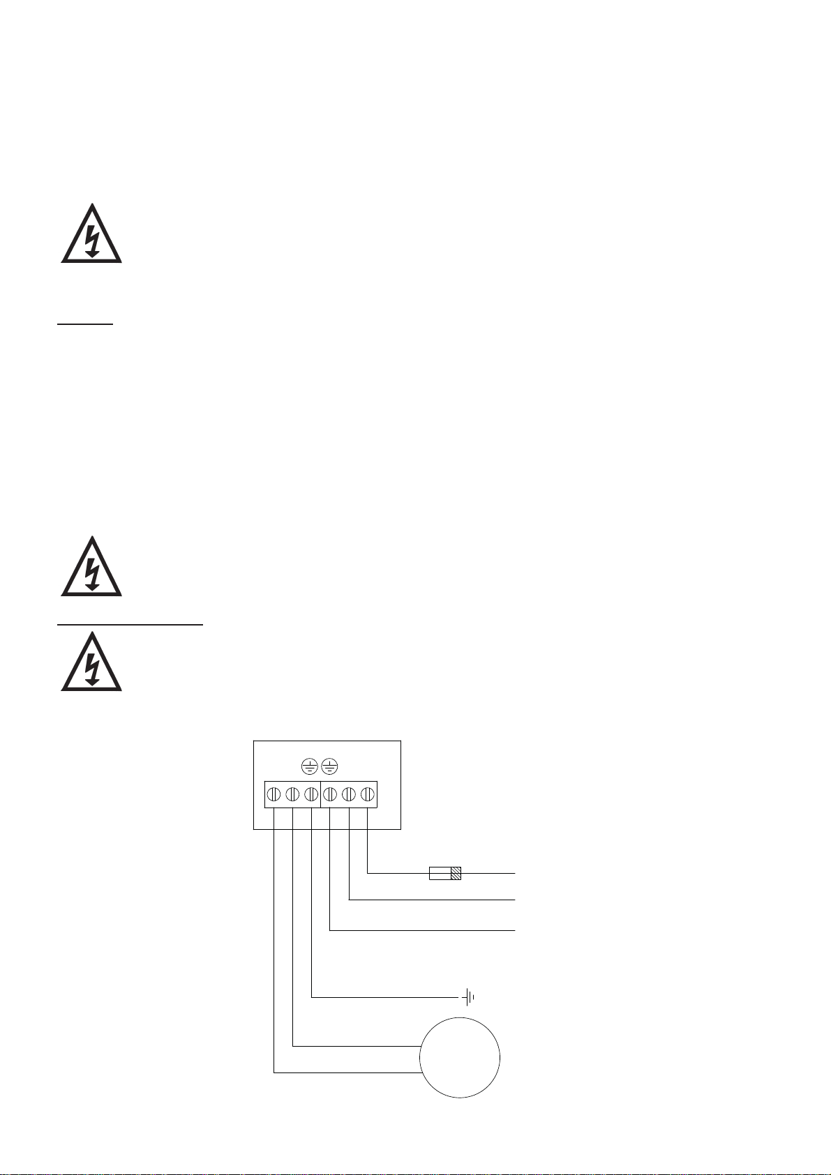
Wiring Diagrams
The supply cord and internal wiring within the terminal box are routed and
secured to ensure compliance with the electrical standard EN 60335-1. It
is essential that any disturbance of this internal wiring is avoided and the
factory routing and securing of all internal wiring is always maintained.
1
3
2
V
U
6
5
4
N
L1
PRESSURE
CONTROL
MODULE
FUSE
L
SUPPLY
230 V
N
1 Phase
50 Hz
E
GREEN/YELLOW
BLUE
BROWN
- 4 -
E
MOTOR
Fig. 3

Fuses
The following fuse size should be used.
Model Fuse Size (AMPS)
All Models 13
Intermediate Connecting Cord Replacement
The intermediate connecting cord (pump supply cord) which connects the pump to the
control module cannot be replaced. If the cord is damaged the pump should be scrapped.
Cable Gland Fitting Instructions (Pressure Control Module)
See Pressure Control Module instruction book.
Intermediate Connecting Cord Extension (Boostamatic Diver 35 and 45)
The intermediate connecting cord which connects the pump to the control module is of a
type suitable for outdoor use. Cord specification is as follows:
H07RN-F3 G 1.0 mm² - 10 amp rating.
If an extension cord is necessary a cord of the proper type and rating must be used.
In general for 230 volt pumps on distances up to 40 metres (inclusive of original cord
length) the same specification cord as fitted to the pump can be used. For distances
above 40 metres a larger cord size may be required due to voltage drop and advice must
be obtained based upon installation details.
Any connectors or junction boxes must be specifically suited for outdoor use and
installed in accordance with manufacturers instructions.
Any cable routed underground must be protected to local standards.
NOISE
The equivalent continuous A-weighted sound pressure level at a distance of 1 metre
from the pumpset does not exceed 70 dB(A) for all models.
COMMISSIONING
WARNINGS:
The motor casing can become very hot under normal operating
conditions, care should be taken to ensure it cannot be touched during
operation.
Do not run pump without guards and terminal box lids correctly fitted.
Care should be taken to protect the pump from freezing.
The pump chamber must be full of liquid at all times. Seal damage will
result if the pump runs dry.
Ensure electrical supply is compatible with the details that are stated on the pump rating
plate. (The wrong voltage or frequency can be dangerous and may damage the pump.)
Priming
The pump should be fully submerged before starting, take care when submerging the
pump to ensure all air is purged from the casing. This is done by slowly submerging the
pump and gently agitating whilst doing so.
- 5 -
Cont ...
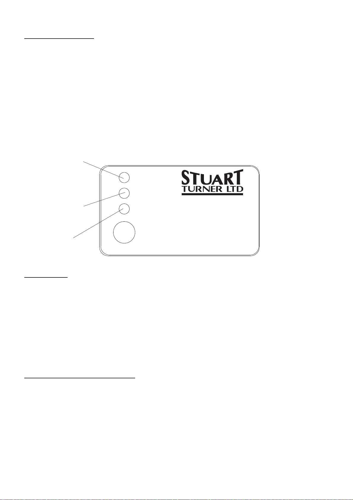
Starting The Pump
Turn on the electrical supply and the green L.E.D. ‘power on’ lights up. The yellow
L.E.D. lights up when the pump is running (Fig. 4).
The pump will run until the system is completely charged and the maximum pressure
reached. All taps or outlets on the system need to be operated starting with the highest
outlet. This is to release air that may be trapped in the system. If the failure (red) L.E.D.
lights up, this indicates that the pump is out of liquid or priming is incomplete. In the
event of this happening, check liquid supply to pump. If all is in order keep the RESTART
button depressed with a tap open and wait until the red failure light goes out. When the
button is released and the tap closed, the pressure control module will stop the pump at
its maximum pressure. Do not run against a closed valve for periods longer than 5
minutes.
Power on L.E.D.
(Green)
Power on
Pump on
PRESSURE
Pump running L.E.D.
(Yellow)
Failure L.E.D.
(Red)
Failure
Restart
230V ~ 50-60 Hz, 6A max. 10bar max. Ambient 40°C max. Water Temp 65°C max.
CONTROL MODULE
STUART TURNER LTD
HENLEY-ON-THAMES
OXFORDSHIRE
RG9 2AD, ENGLAND
DISCONNECT SUPPLY BEFORE OPENING
Pressure Control
Panel
Fig. 4
Functioning
Once the commissioning operation is completed, the module will perform all pump
control operations automatically. Note: After closing any outlet there will be a small delay
time before the pump stops operating, which is normal. When particular operational
breakdowns occur, such as liquid failure, the module recognises the breakdown and the
red L.E.D. FAILURE light comes on. The pump stops operating to prevent damage caused
by its working in the absence of liquid. After rectification of the failure, the system is
restarted by depressing the restart button.
Carefully check pump and pipework for leaks whilst pump running and stationary before
leaving the installation unattended.
For Further Technical Support
Note: When pumps are installed in another manufacturers original equipment, please
contact the manufacturer for advice.
Phone the Stuart Turner Pump Assist team on 0844 98 000 97. Our staff are trained to
help and advise you over the phone or arrange for a service engineer to call.
- 6 -
Cont ...

MAINTENANCE
WARNINGS:
Care should be taken to protect pump from frost and freezing.
Cleaners, disinfectants and descalents
On installations where chemical disinfectants or descalents are periodically
used, the compatibility of the chemical solution regarding the pump must be
considered.
Acid based descalents and aggressive cleaning agents must not come into
contact with the pump. The pump must be removed from the system prior to the
use of these products. The system should be flushed to remove all chemicals
before the pump is re-connected.
If in any doubt as to the suitability of the chemical solutions refer to Stuart
Turner Ltd.
STORAGE
If this product is not installed immediately on receipt, ensure that it is stored in a dry, frost
and vibration free location in its original packaging.
TROUBLE SHOOTING GUIDE
Symptoms Probable Cause Recommended Action
Pump will not start.
Control module failure
light illuminated.
Liquid supply low. Check liquid level in the supply tank and all stopcocks are
open.
Reset the control module by depressing the restart button.
Inlet filter blocked
(if fitted).
Electrical supply. Check all electrical switches are on.
Static inlet or outlet head
is greater than permitted.
Remove and clean filter gauze.
Reset control unit.
Is the correct fuse fitted?
Is the circuit breaker set?
Re-position control module.
(See siting of the pump and limits of application section).
- 7 -

Stuart Turner Ltd, Henley-on-Thames, Oxfordshire RG9 2AD ENGLAND
Tel: +44 (0) 1491 572655, Fax: +44 (0) 1491 573704
email: pumps@stuart-turner.co.uk web: www.stuart-turner.co.uk
V.A.T. REG. No. 199 0987 92. Registered in England No. 88368. Registered Offi ce: Market Place, Henley-on-Thames
Issue No. 0812/1-01 Pt. No. 19718

Diver 35/45 Pump
OPERATING INSTRUCTIONS
Please leave this instruction booklet with the pump as it
contains maintenance and safety information
(Original Instructions)

SUBMERSIBLE MODELS
Clean Water Models
Diver 35
Diver 45
INDEX . . . . . . . . . . . . . . . . . . . . . . . . . . . . . . . . . . . . . . . . . . . . . . . . Page No
Application . . . . . . . . . . . . . . . . . . . . . . . . . . . . . . . . . . . . . . . . . . . . . . . . . . . . . . . . . . . . . . . . 2
Product Description . . . . . . . . . . . . . . . . . . . . . . . . . . . . . . . . . . . . . . . . . . . . . . . . . . . . . . . . . 3
Limits of Application . . . . . . . . . . . . . . . . . . . . . . . . . . . . . . . . . . . . . . . . . . . . . . . . . . . . . . . . . 3
Technical Specifi cation . . . . . . . . . . . . . . . . . . . . . . . . . . . . . . . . . . . . . . . . . . . . . . . . . . . . . . 4
Connections. . . . . . . . . . . . . . . . . . . . . . . . . . . . . . . . . . . . . . . . . . . . . . . . . . . . . . . . . . . . . . . 5
Siting of the Pump . . . . . . . . . . . . . . . . . . . . . . . . . . . . . . . . . . . . . . . . . . . . . . . . . . . . . . . . . . 6
Pipework . . . . . . . . . . . . . . . . . . . . . . . . . . . . . . . . . . . . . . . . . . . . . . . . . . . . . . . . . . . . . . . . . 7
Electrical Installation . . . . . . . . . . . . . . . . . . . . . . . . . . . . . . . . . . . . . . . . . . . . . . . . . . . . . . . . 8
Noise . . . . . . . . . . . . . . . . . . . . . . . . . . . . . . . . . . . . . . . . . . . . . . . . . . . . . . . . . . . . . . . . . . . . 10
Commissioning . . . . . . . . . . . . . . . . . . . . . . . . . . . . . . . . . . . . . . . . . . . . . . . . . . . . . . . . . . . . 10
Maintenance . . . . . . . . . . . . . . . . . . . . . . . . . . . . . . . . . . . . . . . . . . . . . . . . . . . . . . . . . . . . . . 10
Trouble Shooting Guide . . . . . . . . . . . . . . . . . . . . . . . . . . . . . . . . . . . . . . . . . . . . . . . . . . . . . . 12
Environment Protection . . . . . . . . . . . . . . . . . . . . . . . . . . . . . . . . . . . . . . . . . . . . . . . . . . . . . . 12
IMPORTANT NOTES
Please read these instructions fully before starting the
installation:
The installation must comply with the relevant water supply,
electrical and building regulations and be installed by a
competent person.
If in doubt, consult Stuart Turner Ltd.
APPLICATION
This pump set must not be used for any other application without the
written consent of Stuart Turner Limited and in particular, must not be
connected directly to the mains water supply or used outside the
conditions specified in the limits of application.
This appliance is not intended for use by persons (including children)
with reduced physical, sensory or mental capabilities, or lack of
experience and knowledge, unless they have been given supervision
or instruction concerning use of the appliance by a person responsible
for their safety.
Children should be supervised to ensure that they do not play with the
appliance.
- 2 -

General
The Diver pump range is designed for re-circulation, drainage and transfer of clean fresh
water in outdoor or indoor applications.
All models within the range incorporate an adjustable float switch assembly which
provides automatic pump control.
These models are suitable for clean water only.
PRODUCT DESCRIPTION
Electric motor driven submersible pump with float switch control.
Motor
All motors are induction type, permanent capacitor, fitted with integral auto-resetting
thermal overload protection, IPX8 enclosure, class ‘B’ insulation and continuously rated.
The motor is encapsulated in a casing and protected from water ingress by a mechanical
seal running on a shaft sleeve, lubricated with a biodegradable vegetable oil.
Pump
All models are close coupled to the motor and are of centrifugal design and are supplied
as standard with a hose connector and are supplied pre-fitted with a 15 metre mains
supply cord.
Standard pump materials of construction of major wetted parts are as follows.
Model Body Impeller Shaft
All models
Glass filled
Polypropylene
Polyamide Stainless Steel
Motor
Encapsulent
Stainless Steel/
Cast Aluminium
Outer
Sleeve
Stainless
Steel
Mechanical
Seal
Nitrile/
Carbon/
Ceramic
Float Switch
Factory fitted assembly for automatic pump control, provided as standard on the Diver
range. The wetted materials of construction are polypropylene.
LIMITS OF APPLICATION
Max.
Model
Diver 35 35 4 10 300 30 34
Diver 45 35 4 10 300 30 42
Liquid
Temp.
o
C
Min.
Liquid
Temp.
o
C
Max.
Immersion
Depth
(m)
Min.
Immersion
Depth
(mm)
Max.
No.
Starts/h
Head (pump
closed valve)
Max.
(m)
- 3 -
Cont ...

TECHNICAL SPECIFICATION
Nominal
Model
Diver 35 230/1/50 774 720 3.7 IPX8 Continuous 350 8.5 1
Diver 45 230/1/50 1012 1000 4.7 IPX8 Continuous 387 9.2 1
Supply
Max. Watts
Consumed
Watts
Output
(Motor)
Full
Load
Current
(AMPS)
Enc.
Rating
Duty
Rating
Dims
(mm)
H
Gross
Weight
(packed)
kg
Stuart Turner reserve the right to amend the specification in line with its policy of
continuous development of its products.
No. of
Pump
Stages
H
164O
Fig. 1
- 4 -
Cont ...

CONNECTIONS
Diver pumps have a 1 " BSP female connection and are supplied with a 25 mm hose
connector.
Pump Type
All models G1 F 25
Pump
Outlet
Hose Bore (mm)
Fig. 2
Inlet
Hose
Connector
- 5 -
Outlet
Fig. 3

SITING OF THE PUMP
WARNINGS:
Do not run against a closed valve for periods longer than 5 minutes.
The water in and around the pump must not be allowed to freeze. This
will result in pump damage.
Do not under any circumstances use the supply cord fitted, as a
means to carry or lower the pump into position on installation. Attach
a rope sling to handle.
Do not allow plastic pump parts to come into contact with solder flux,
oil or cellulose based paints, paint thinners or strippers, acid based
descalents or aggressive cleaning agents.
Never run pump whilst sucking air only as the motor will overheat.
To prevent this happening always install pump in the vertical position
and ensure fully submerged.
When siting the pump ensure its base is raised slightly from the
bottom of the sump reducing the possibility of blocking the filter with
debris or drawing in small stones.
General
If the pump is to be run continuously it must be installed in a vertical position and must
be submerged at all times to avoid overheating of the motor.
If the float switch is in use to empty a tank the pump may be operated partially
submerged for short periods (see float switch operation section for further details).
The pumps should be positioned away from pond plants (if applicable) to maximise flow
and prevent entanglement.
Float Switch Operation
All Diver models are fitted with a float switch for automatic operation.
The following guide will help you get the most out of your pump.
The pump must never run dry, needing a minimum water depth of 300 mm at all times.
Adjustment of the float switch is achieved by lengthening or shortening the cable through
the moulded cable retention slot, which is located in the pump handle (Figs 4 and 5).
Note: When inserting cable into slot ensure it is fully engaged.
Pump Handle
Fig. 4
Moulded cable
retention slot
- 6 -
Fig. 5
Float Switch cable shown
slotted into position

If modification of the level setting is required refer to Figures 6 and 7 and the following
chart.
Wherever the pump is installed it must have sufficient dimensions for the float switch to
operate freely (Fig. 8), retaining a minimum water depth as previously stated. The pump is
continuously rated when fully submerged but should only be run for short periods (10 mins)
when the water drops to the minimum level. The number of starts should not exceed 30
per hour.
Note: It is not possible to empty the sump completely, a minimum depth must remain
(Figs. 6 & 7).
470
START
A
STOP
B
Fig. 6 Min. Float
Switch Movement
C
START
D
STOP
E
Fig. 7 Max. Float
F
450
Fig. 8 Min. Size Of Sump
Switch Movement
ABCDEF
PUMP TYPE
START
(MIN.ADJ)
STOP
(MIN.ADJ)
CABLE
(MIN.ADJ)
START
(MAX.ADJ)
STOP
(MAX.ADJ)
CABLE
(MAX.ADJ)
All models 410 300 220 460 200 320
Chart shows min. and max. float switch adjustment
PIPEWORK
WARNING
Ensure pipework from pump is independently supported to prevent forces
being transferred to outlet branch.
General
All models are supplied with a hose connector (see pump connection section for details)
which can be screwed directly into the pump discharge connection.
The hose connector is suitable for a 25 mm hose size. For best flow use the largest bore
pipe possible minimising 90° bends. Small pipe sizes will reduce the pump performance.
The discharge pipework must be independently supported to prevent forces being
transferred to the pump outlet branch.
Cont ...
- 7 -

ELECTRICAL INSTALLATION
WARNINGS:
The electrical installation must be carried out in accordance with the
current national electrical regulations and installed by a competent
person.
A residual current device having a rated current not exceeding 30 mA
MUST be installed in the supply circuit. This may be part of a
consumer unit or a separate unit.
Before starting work on the electrical installation, ensure the power
supply is isolated.
This appliance must be earthed.
Isolate all appliances in the water from the electrical supply before
putting your hands in the water.
The power supply cord of this pump cannot be replaced. If the cord is
damaged, the pump should be scrapped.
If the pump is used to empty a swimming pool, the pump must not be
used when people are in the water.
All motors are thermally protected by an integral auto-resetting thermotrip and are rated
for continuous use.
Earthing
This appliance must be earthed via the supply cord.
Electrical Connection
The motor is provided with a factory fitted supply cord and plug. This must be connected
to the mains supply via a 13 Amp double pole switched, socket outlet in compliance with
BS 1363-2.
The socket outlet should be mounted in an easily accessible position and should be
labelled if confusion is possible, to allow easy identification of the pump isolating switch.
Wiring
The moulded plug fitted to this appliance is not waterproof - keep dry.
The supply cord is factory fitted with a moulded plug incorporating a fuse, the value of
which is indicated on the pin face of the plug. Should the fuse need to be replaced, an
ASTA approved BS 1362 fuse must be used of the same rating, marked thus,
fuse cover is detachable, never use the plug with the cover omitted. If a replacement fuse
cover is required, ensure it is of the same colour as that visible on the pin face of the plug
(i.e. red or orange).
If the plug supplied is not suitable for your socket outlet, it should be cut off and
destroyed.
. If the
WARNING: A plug with bared flexible cords is hazardous if engaged in a
live socket outlet.
Should the moulded plug fitted have to be removed from the cable, then the following
should be adhered to.
- 8 -
Cont ...

The wires in this mains lead (supply cord) are coloured in accordance with the following
code:
Green & Yellow: Earth Blue: Neutral Brown: Live
As these colours may not correspond with the coloured markings identifying the
terminals in your plug, proceed as follows:
The wire which is coloured green and yellow must be connected to the terminal in the
plug which is marked with the letter ‘E’ or by the earth symbol
green and yellow.
The wire which is coloured blue must be connected to the terminal which is marked with
the letter ‘N’ or coloured black or blue.
The wire which is coloured brown must be connected to the terminal which is marked
with the letter ‘L’ or coloured brown or red.
or coloured green or
Fuses
The following fuse size should be used with the appropriate pump.
Model Fuse Size (AMPS)
All Models 13
Supply Cord Replacement
The power supply cord of this pump cannot be replaced. If the cord is damaged, the
pump should be scrapped.
Float Switch Cord Replacement
The float switch cord cannot be replaced. If the cord is damaged the pump should be
scrapped.
Supply Cord Extension (Pump)
The pumps are fitted with a supply cord suitable for outdoor and underwater use. The
cord specification is as follows:-
Pump Type Cord Type Cord Length (m)
Diver HO7RN-F3 G 1.0 mm² 15
If an extension cord is necessary a cord of the proper type and rating must be used.
In general for 230 volt pumps on distances up to 40 metres (inclusive of original cord
length) the same specification cord as fitted to the pump can be used. For distances
above 40 metres a larger cord size may be required due to voltage drop and advice must
be obtained based upon installation details.
Any connectors or junction boxes must be specifically suited for outdoor use and
installed in accordance with manufacturers instructions.
Any cable routed underground must be protected to local standards.
Float Switch Cord Extension
The float switch cord cannot be extended.
Cont ...
- 9 -

NOISE
The equivalent continuous A-weighted sound pressure level at a distance of 1 metre
from the pumpset does not exceed 70 dB(A).
COMMISSIONING
WARNING:
The pump chamber must be full of water at all times. Damage will
result if pump runs dry.
1. The pump must be fully submerged before starting. Take care when submerging the
pump to ensure all air is purged from the casing. This is done by slowly submerging
the pump and gently agitating whilst doing so. This will enable any trapped air
pockets to be released.
2. Turn on the electrical supply and water movement should be immediately evident
from pump outlet. If it is not, repeat step 1.
For Further Technical Support
Note: When pumps are installed in another manufacturers original equipment, please
contact the manufacturer for advice.
Phone the Stuart Turner Pump Assist team on 0844 98 000 97. Our staff are trained to
help and advise you over the phone or arrange for a service engineer to call.
MAINTENANCE
WARNING
The water in and around the pump must not be allowed to freeze.
This will result in pump damage.
Provision should be made for easy access to the pump to allow for regular maintenance.
The integral inlet filter grille and any additional pre-filters should be checked periodically
and cleaned if required. It is important the filters are clean and free from debris which in
turn ensures the pump will always run at maximum efficiency. A blocked filter can cause
damage to the pump.
The pump must be cleaned as follows:-
Diver Range
1) Disconnect electrical supply before working on pump.
2) Release system pressure from pipework and remove pump from water (do not use
cable to lift pump).
3) Clean integral inlet filter grilles using water pressure from a hose pipe (Fig. 9).
4) Refer to commissioning section for instructions on re-starting pump.
- 10 -
Cont ...

Inlet Filter Grille
Fig. 9
STORAGE
If this product is not installed immediately on receipt, store in a frost and vibration free
location in its original packaging.
- 11 -
Cont ...

TROUBLE SHOOTING GUIDE
Symptoms Probable Cause Recommended Action
Pump stops running. Thermal overload
protection has
tripped.
Pump will not start. Pump not connected
to the electricity
supply.
Impeller Jammed. Clean away debris from the impeller.
Disconnect the power supply to the
pump.
Allow to cool for 30 mins.
Check to ensure the pump is connected
to the correct voltage supply.
Check to ensure the impeller is not
jammed and can rotate freely.
Check to ensure water to be pumped
does not exceed recommended
temperature, ensure pump has not run
dry and is fully submerged.
Check probable causes and remedy,
allow to cool reinstall and connect cable.
Check the cable is connected correctly
and power supply is switched on.
Check fuse.
Float switch not
working.
Check the float switch by hand (do not
attempt to dismantle float switch) for
further advice contact Stuart Turner.
Pump runs but no
water is supplied.
Low water level. Ensure the pump is fully submersed
below the water level.
Ensure that the pump is not able to suck
air in (low water level).
Discharge pipe
clogged.
Remove pipe and ensure the discharge
is clear of any debris.
Suction filter blocked. Check inlet pre-filters (if fitted), are free
from blockages.
ENVIRONMENT PROTECTION
Your appliance contains valuable materials which can be recovered or recycled.
At the end of the products’ useful life, please leave it at an appropriate local civic waste
collection point.
- 12 -
Cont ...

YOUR 1 YEAR GUARANTEE
Stuart Pumps are guaranteed by Stuart Turner Limited to be free from defects in
materials or workmanship for the applicable guarantee period from the date of purchase.
The applicable guarantee period is stated in the installation booklet supplied with the
pump. Within the guarantee period we will repair, free of charge, any defects in the pump
resulting from faults in material or workmanship, repairing, exchanging parts or exchanging
the whole unit as we may reasonably decide.
Not covered by this guarantee: Damage arising from incorrect installation, improper use,
unauthorised repair, normal wear and tear and defects which have a negligible effect on
the value or operation of the pump.
Reasonable evidence must be supplied that the pump has been purchased within the
applicable guarantee period prior to the date of claim (such as proof of purchase or the
pump serial number).
This guarantee is in addition to your statutory rights as a consumer. If you are in any
doubt as to these rights, please contact your local Trading Standards Department or
Citizen’s Advice Bureau.
In the event of a claim please telephone Stuart Turner Limited on 0844 980 0097 or
return your pump with accessories removed, plugs, pipes etc. If you have any doubt about
removing a pump, please consult a professional.
Proof of purchase should accompany the returned pump to avoid delay in investigation
and dealing with your claim.
- 13 -

NOTES
- 14 -

NOTES
- 15 -

DECLARATION OF CONFORMITY
2006/95/EC
BS EN 60335-1, BS EN 60335-2-41, EN 50366
2004/108/EC
BS EN 55014-1, BS EN 55014-2, BS EN 55022, BS EN 61000-3-2, BS EN 61000-3-3,
BS EN 61000-4-2, BS EN 61000-4-3, BS EN 61000-4-4, BS EN 61000-4-5, BS EN 61000-4-6,
BS EN 61000-4-11
IT IS HEREBY CERTIFIED THAT THE STUART ELECTRIC MOTOR DRIVEN PUMP COMPLIES
WITH THE ESSENTIAL REQUIREMENTS OF THE ABOVE E.E.C. DIRECTIVES.
RESPONSIBLE PERSON
AND MANUFACTURER STUART TURNER LIMITED
HENLEY-ON-THAMES, OXFORDSHIRE
RG9 2AD ENGLAND.
Signed . . . . . . . . . . . . . . . . . . . . . . . . . . . . . . . . . . . . . . . . .
Stuart Turner are an approved company to BS EN ISO 9001:2000
Business Development Director
Stuart Turner Ltd, Henley-on-Thames, Oxfordshire RG9 2AD ENGLAND
Tel: +44 (0) 1491 572655, Fax: +44 (0) 1491 573704
email: pumps@stuart-turner.co.uk web: www.stuart-turner.co.uk
V.A.T. REG. No. 199 0987 92. Registered in England No. 88368. Registered Offi ce: Market Place, Henley-on-Thames
Issue No. 4311/1-01 Pt. No. 19653
 Loading...