

Stuart Turner Showermate U1.8 bar Twin User Manual

Installation, Operation & Maintenance
Instructions
Please leave this instruction booklet with the home owner as it contains
important guarantee, maintenance and safety information
Read this manual carefully before commencing installation.
This manual covers the following products:
Showermate U2.6 bar Single
Pt. No. 46534
Showermate U2.6 bar Single - Export
Pt. No. 46537
Showermate U1.8 bar Twin
Pt. No. 46532
Showermate U2.6 bar Twin
Pt. No. 46533
Showermate U2.6 bar Twin - Export
Pt. No. 46536
FOR POSITIVE OR NEGATIVE HEAD APPLICATIONS
CE compliant product

PRODUCT DESCRIPTION
Electric motor driven single or twin ended peripheral pumps complete with an automatic
control system, consisting of flow switches, pressure switches, pressure vessels and
electronic control.
APPLICATION
Showermate Universal pumps are suitable for positive or negative head installation
conditions. The pumps are designed for single shower pressure boosting applications in
vented stored water systems. Inlet pressures to the pump and ambient temperatures must
not exceed the values given in the technical specifications.
This pump set must not be used for any other
application without the written consent of Stuart
Turner Limited and in particular, must not be
connected directly to the mains water supply.
This appliance can be used by children aged from
8 years and above and persons with reduced
physical, sensory or mental capabilities or lack of
experience and knowledge if they have been given
supervision or instruction concerning use of the
appliance in a safe way and understand the hazards
involved. Children shall not play with the appliance.
Cleaning and user maintenance shall not be made by
children without supervision.
Children should be supervised to ensure that they do
not play with the appliance.
WARNING - Washer/condenser dryers and condenser
dryers.The pump must not be used in the water
supply line to a washer/ condenser drier or a
condenser drier, which uses a constant flow of
cold water to aid the condenser drying process, as
damage can occur to the pump. If in doubt or for
further information contact Stuart Turner Ltd.
Please read installation details carefully as they are intended to ensure this product
provides long, trouble free service. Failure to install the unit in accordance with the
installation instructions will lead to invalidation of the warranty.
Cont ...
- 2 -

STORAGE
If this product is not to be installed immediately on receipt, ensure that it is stored in a
dry, frost and vibration free location in its original packaging.
CONTENTS Page
Checklist . . . . . . . . . . . . . . . . . . . . . . . . . . . . . . . . . . . . . . . . . . . . . . . . . . . . . . . . 4
Pre-Installation . . . . . . . . . . . . . . . . . . . . . . . . . . . . . . . . . . . . . . . . . . . . . . . . . . . 4
Important Facts - read before commencing installation . . . . . . . . . . . . . . . . . . . . 5
Location . . . . . . . . . . . . . . . . . . . . . . . . . . . . . . . . . . . . . . . . . . . . . . . . . . . . . . . . 6
Pump Connections . . . . . . . . . . . . . . . . . . . . . . . . . . . . . . . . . . . . . . . . . . . . . . . . 10
Electrical Installation . . . . . . . . . . . . . . . . . . . . . . . . . . . . . . . . . . . . . . . . . . . . . . . 14
Commissioning . . . . . . . . . . . . . . . . . . . . . . . . . . . . . . . . . . . . . . . . . . . . . . . . . . . 17
Maintenance . . . . . . . . . . . . . . . . . . . . . . . . . . . . . . . . . . . . . . . . . . . . . . . . . . . . . 18
Technical Specifi cation . . . . . . . . . . . . . . . . . . . . . . . . . . . . . . . . . . . . . . . . . . . . . 20
Trouble Shooting . . . . . . . . . . . . . . . . . . . . . . . . . . . . . . . . . . . . . . . . . . . . . . . . . 21
Guarantee . . . . . . . . . . . . . . . . . . . . . . . . . . . . . . . . . . . . . . . . . . . . . . . . . . . . . . . 25
- 3 -
Cont ...
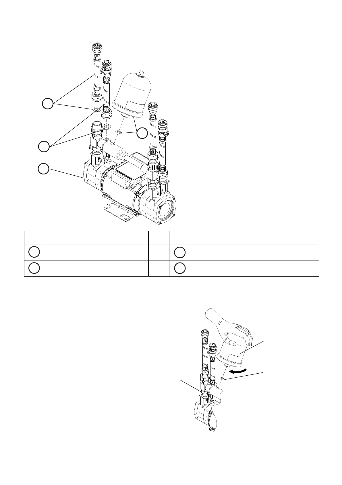
CHECKLIST
B
C
A
IMPORTANT: With the pump
removed from its packaging check
for any damage prior to installation.
If any damage is found contact
Stuart Turner Ltd within 24 hours of
receipt.
D
Fig. 1
Item
A
B
Description Qty
Pump 1 ISO Hose & sealing washer 2(1)
Plain Hose & sealing washer 2(1) Tank & fibre washer 1
Item
C
D
Your product may vary slightly from the picture above.
PRE-INSTALLATION CHECK
The pressure vessel is supplied as a
separate item, and will need to be fitted
prior to installing the pump.
Install the pressure vessel ensuring
the fibre washer is in place and hand
tighten.
Note: Do not overtighten pressure
vessel.
After fitting the pressure vessel ensure
the retaining nut at the base of the
assembly is still hand tight and the
cable connecting the pressure switch
has not been strained during the
assembly.
Do not lift/carry the pump by the
transfer pipe or pressure vessel
manifold.
Retaining nut
Description Qty
Pressure vessel
Fibre washer
Fig. 2
Cont ...
- 4 -
1 READ BEFORE COMMENCING PUMP INSTALLATION
A. Water storage capacity.
1.11 The hot and cold water storage capacity must be sufficient to meet the flow rates
required by the pumped equipment and any other water using fittings and
appliances, which may be operated simultaneously.
1.12 Ensure the pump is primed as described in the priming section before starting,
damage to the shaft seal will result otherwise. See Section 5 - Commissioning.
B. Water temperature
The water entering the pump must be controlled as follows:
o
C.
o
C.
you must consult the
o
bends.
1.13 The maximum allowable water temperature is 65
1.14 The minimum allowable water temperature is 4
1.15 DO NOT fit a pump if the hot water is heated via a method whereby the water
temperature cannot be controlled, such as solar or solid fuel
PumpAssist team at Stuart Turner Ltd.
C. Pipework - General
1.16 Secure pipework: Ensure pipework to and from pump is independently
supported & clipped to prevent forces being transferred to inlet and outlet
branches of pump.
1.17 Flux: Solder joints must be completed and flux residues removed prior to pump
installation (flux damage will void any warranty).
1.18 Pipework design: Care should be taken in the design of pipework runs to
minimize the risk of air locks e.g. use drawn bends rather than 90
1.19 DO NOT introduce solder flux to flexible hoses, pumps or pump parts
manufactured from plastic.
1.20 DO NOT allow contact with oil or cellulose based paints, paint thinners or
strippers, acid based descalents or aggressive cleaning agents.
1.21 DO NOT install a non-return valve, or devices which contain non-return
valves, in the suction (inlet) pipework to the pump. The pump must be free
to vent to the supply tank at all times.
1.22 DO NOT bend the flexible hoses beyond 30
o
. They must be installed as
straight as possible.
1.23 DO NOT connect this pump to the mains water supply.
1.24 DO NOT stress the inlets/outlets of the pump from the misalignment of
hoses/pipework.
D. Plumbing & Electrical Installation Regulations
1.25 The plumbing installation must comply with “The Water Supply (Water Fittings)
Regulations 1999” and “BS 6700” building regulations.
1.26 The plumbing installation must be installed by a qualified person.
1.27 The electrical installation must be carried out in accordance with the current
national electrical regulations.
1.28 The electrical installation must be installed by a qualified person.
E. Pressure vessel
1.29 Pressure vessel is charged at the factory see Section 6 - Maintenance for details.
- 5 -

2 LOCATION - GENERAL
2.11 Access: For emergencies and maintenance the pump must be
easily accessible.
2.12 Protection: The pump must be located in a dry position, frost free and
protected from freezing, particularly when installed in a loft (not
recommended).
2.13 Ventilation: Ensure an adequate air flow to cool the pump. Separate
the pump from other appliances that generate heat. An 80 mm (3 “) air
gap must be maintained around the pump.
2.14 Safety: The motor casing can become very hot under normal
operating conditions. Care must be taken to ensure it cannot be
touched during operation.
2.15 Water retention: Site the pump in a location where in the unlikely
event of a water leak, any spillage is contained or routed to avoid
electrics or areas sensitive to water damage.
2.16 Static inlet pressure: Before deciding where to position the unit, check to ensure
the static inlet and outlet heads of water above the pump (Figs. 5 & 6), does not
exceed the maximum permitted limits.
2.17 Pump position: The pump must be positioned on its anti-vibration mounting feet
and as close to the water source as possible.
2.18 Ambient temperature: The pump must be sited in a location where the maximum
ambient temperature does not exceed 40
2.19 Pipework: For optimum performance pipework MUST be 22 mm.
Pipework should only reduce to 15 mm when entering terminal fitting.
2.20 Static outlet pressure: The static outlet head must also be within the maximum
requirement (Figs. 5 & 6).
2.21 Noise: The anti-vibration mounting feet and flexible hoses which are supplied
as standard, and a precaution to reduce noise transmission, however care must
be taken when mounting the pump that any noise is not amplified through loose
panels or pipework. Do not screw down the pump.
2.22 Direction of flow: Ensure the water flow is in the direction of the arrow that is
marked on the flow switch reed clamp (vertically upwards).
2.23 Flexible hoses: Use only Stuart Turner supplied hoses.
2.24 Isolating valves: Separate isolating valves (non restrictive) must be fitted to
allow easy pump service.
2.25 Strainers: To ensure the pump does not become damaged as a result of debris
in the water supply, stainers must be fitted in line (not supplied).
2.26 Preferred pump location: The preferred pump location is at floor level next to
the hot water cylinder or a level that is below the secondary tapping that feeds
the pump. The pump location is also dependent on limitations of the static inlet
and outlet heads of the installation. For guidance on limitations and
recommended location, consult the following relevant section for hot or cold water
installation.
o
C.
- 6 -
Cont ...
2.27 Non-preferred pump location: If it is not possible to locate the pump in the
preferred area due to site limitations and it is necessary to position the unit in the
loft, or in a position above the secondary tapping that feeds the pump, then there
is an increased risk of air locks. This risk must be eliminated.
The following measure is a suggestion that may overcome the problem:
Always use an Essex or side entry flange as the hot pump connection and a
“U” bend or downward loop in the supply pipe to the pump of 350 mm depth
before rising to the pump should ensure the cylinder vents its air up the
expansion pipe, not up the pump feed (Figs. 3 & 4).
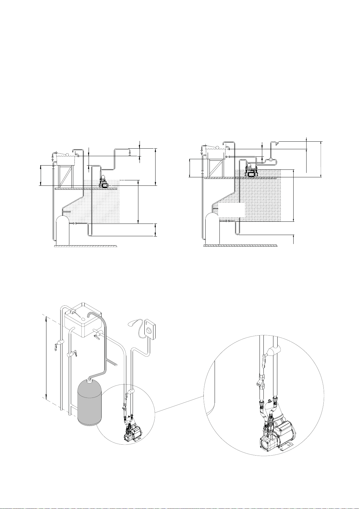
200 mm
min
200 mm min
Negative
head
Negative
Max. inlet head 6 m
Min. inlet head 0.5 m
head
least preferred
area
Max. outlet head 6 m
Max. inlet head 6 m
Min. inlet head 0.5 m
hot water
services
least preferred area
Max. outlet head 6 m
Fig. 3 - Single Pump
2 LOCATION - SINGLE PUMP
Max. static inlet pressure 6 m
350 mm
min
350 mm
Fig. 4 - Twin Pump
Negative Duty Single Pump System
Fig. 5
Cont ...
- 7 -
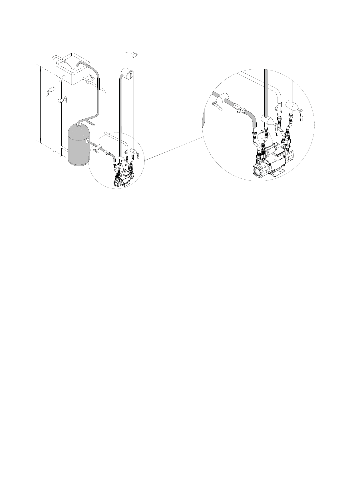
2 LOCATION - TWIN PUMP
Max. static inlet pressure 6 m
Negative Duty Twin Pump System
Fig. 6
Cold water connection:
2.28 The cold water supply: The supply must be AIR FREE and have a
DEDICATED CONNECTION to the tank which should be via a tank connector,
positioned at a slightly lower level (25 mm minimum) than the feed pipe to the hot
water cylinder.
Do not connect to the mains.
2.29 Location: The pump must, for optimum performance, be sited as close as
possible to and never more than 4 metres from the HOT WATER cylinder. The
pump should always be sited BELOW the HOT WATER take-off from the cylinder.
- 8 -
Cont ...
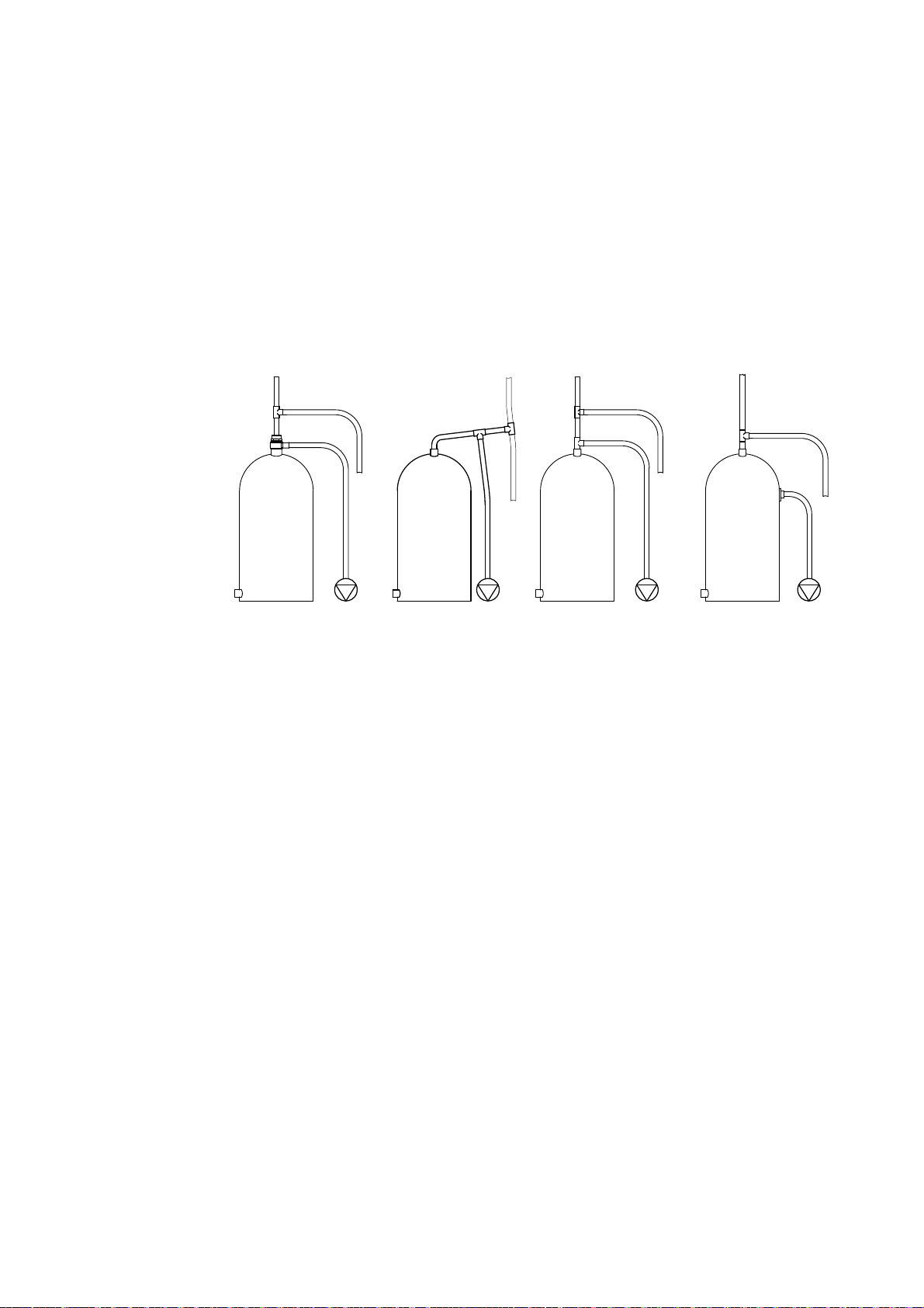
Hot water connection:
2.30 Hot water cylinder or storage tank: When a hot water cylinder or storage tank
is used, ensure the pipework size from the cold water storage to the hot water
storage is of adequate size and a minimum of 22 mm.
2.31 Hot water supply: The pump must be supplied with a dedicated feed direct
from the hot water cylinder or storage tank, ensuring an air free connection to the
cylinder, which can be made by one of the methods shown in Fig. 7. We
recommend the use of the Stuart flange TE Part No 27800.
2.32 Expansion pipe: When the method of connection is to be made via the
expansion pipe, the BASE of the cold water storage tank MUST be at least
1 metre above the connection/take off of the hot water storage cylinder feeding
the pump.
Fig. 7
G 1 Stuart flange
top entry (TE)
with 22 mm
pipework to
pump
.
Off expansion
pipe with rising
22 mm offset
and 22 mm
pipework to
pump.
Off vertical
expansion pipe with
22 mm pipework to
pump.
Factory installed G ¾
secondary tapping
with 22 mm pipework
to pump.
or
Side mounted Stuart
flange side entry (SE)
with 22 mm pipework
to pump.
- 9 -
Cont ...
 Loading...