

Stuart Turner RG4000 User Manual
Peripheral Pumps
OPERATING INSTRUCTIONS
Please leave this instruction booklet with the pump as it
contains maintenance and safety information
(Original Instructions)
MODELS
Vertical Suction End Suction
RG3300
RG4000
ES4000
ES6000
RG5000
RG6000
INDEX . . . . . . . . . . . . . . . . . Page No
Application . . . . . . . . . . . . . . . . . . . . . . . . . . 2
Product Description . . . . . . . . . . . . . . . . . . . 3
Limits of Application . . . . . . . . . . . . . . . . . . . 3
Technical Specifi cation . . . . . . . . . . . . . . . . 4
Connections . . . . . . . . . . . . . . . . . . . . . . . . 4
Siting of the Pump/Pipework . . . . . . . . . . . . 5
IMPORTANT NOTES
Please read these instructions fully before starting the
installation:
The installation must comply with the relevant water supply,
electrical and building regulations and be installed by a
competent person.
If in doubt, consult Stuart Turner Ltd.
INDEX . . . . . . . . . . . . . . . . . Page No
Electrical Installation . . . . . . . . . . . . . . . . . . 6
Noise . . . . . . . . . . . . . . . . . . . . . . . . . . . . . . 13
Commissioning . . . . . . . . . . . . . . . . . . . . . . 13
Maintenance . . . . . . . . . . . . . . . . . . . . . . . . 15
Trouble Shooting Guide . . . . . . . . . . . . . . . . 16
Environment Protection . . . . . . . . . . . . . . . . 16
APPLICATION
The range of peripheral pumps is designed to pump clean fresh water. Other clean, non
aggressive, non explosive liquids with similar characteristics to water may be pumped.
Consult Stuart Turner for such applications.
The pumps can be used for pressure boosting, fluid transfer and distribution. They are
suitable for flooded suction applications. Alternatively a maximum suction lift of
4.6 metres is permitted when using a Stuart footvalve/strainer.
WARNING AGAINST MISUSE
This pump set must not be used for any other application without the
written consent of Stuart Turner Limited. In particular, it must not be
connected directly to the mains water supply, or used outside the
conditions specified in the limits of application.
This appliance is not intended for use by persons (including children
with reduced physical, sensory or mental capabilities, or lack of
experience and knowledge, unless they have been given supervision
or instruction concerning use of the appliance by a person
responsible for their safety.
Children should be supervised to ensure that they do not play with the
appliance.
- 2 -

PRODUCT DESCRIPTION
Motor:
Induction type, totally enclosed fan ventilated cooling*, continuously rated*, class ‘F’
insulation. Motors comply with IEC34-1. Single phase versions incorporate a permanent
capacitor and integral auto resetting thermal overload protection.
The standard range of motors are suitable for a supply of 230V, 1 phase, 50Hz.
Optional motors are available on certain models to suit various voltages and frequencies
(see technical specification for details).
*Variations of rating and enclosure details can be found in the technical specification
section.
Pump
All models are close coupled to motor.
RG4000 & 6000 are of single stage, peripheral design, with vertical suction and
discharge ports.
ES4000 & 6000 are of single stage, end suction, peripheral design.
Standard pump materials of construction of major wetted parts are as follows: -
Model Body Impeller Shaft Mechanical Seal
ALL Brass Brass Stainless Steel Nitril/Carbon
Ceramic/Stainless Steel
Other seal material options are available on certain models.
LIMITS OF APPLICATION
Model Supply
RG300 230/1/50 80 4 40 4.6* 25.5 50 9.5 600 (6) 35 60
RG4000 230/1/50 80 4 40 4.6* 30.7 50 9.5 600 (6) 30 60
RG5000 230/1/50 80 4 40 4.6* 40 50 9.5 600 (6) 33 60
RG5000DV 230/1/50 80 4 40 4.6* TBA 50 9.5 600 (6) TBA 60
RG5000DV 230/1/60 80 4 40 4.6* TBA 50 9.5 600 (6) TBA 60
RG5000DV 110/1/50 80 4 40 4.6* TBA 50 9.5 600 (6) TBA 60
RG5000DV 110/1/60 80 4 40 4.6* TBA 50 9.5 600 (6) TBA 60
RG6000 230/1/50 80 4 40 4.6* 41.6 50 9.5 600 (6) 19 60
ES4000 230/1/50 80 4 40 4.6* 29.8 50 9.5 600 (6) 31 60
ES6000 230/1/50 80 4 40 4.6* 42.0 50 9.5 600 (6) 19 60
Max.
Liquid
Temp.
o
C
Min.
Liquid
Temp. oC
Max.
Ambient
Air Temp
o
C
Max.
Suction
Lift (m)
Max. Head
(Pump
Closed
Valve) (m)
Max. Viscosity
(Redwood No. 1
Scale)
Centistokes
* With footvalve fitted.
**Max.
Working
Pressure
kPa (bar)
Max.
Inlet
Head
(m)
Max. No.
Starts/h
**Note: Max working pressure is the maximum pressure that can be applied to the
pump internal casing under any installation conditions.
- 3 -
Cont ...

TECHNICAL SPECIFICATION
Nominal
Model Supply
RG3300 230/1/50 180 280 1.3 IP44
RG4000 230/1/50 120 345 1.5 IP44
RG5000 230/1/50 180 395 1.7 IP44
RG5000 DV 230/1/50 TBA TBA TBA IP44 TBA TBA TBA TBA
RG5000 DV 230/1/60 TBA TBA TBA IP44 TBA TBA TBA TBA
RG5000 DV 110/1/50 TBA TBA TBA IP44 TBA TBA TBA TBA
RG5000 DV 110/1/60 TBA TBA TBA IP44 TBA TBA TBA TBA
RG6000 230/1/50 300 520 2.3 IP44
ES4000 230/1/50 120 365 1.6 IP44
ES6000 230/1/50 300 560 2.5 IP44
Watts
Output
(Motor)
Max. Watts
Consumed
Full
Load
(AMPS)
Enc.
Rating
Duty
Rating
Continuous (S1) @
2.5 l/min & above
Continuous (S1) @
2.5 l/min & above
Continuous (S1) @
2.5 l/min & above
Continuous (S1) @
2.5 l/min & above
Continuous (S1) @
2.5 l/min & above
Continuous (S1) @
2.5 l/min & above
Dimensions
(mm)
LWH
208 132 176 5.6
201 126 170 4.6
208 132 176 5.6
201 126 170 5.2
232 126 170 5.2
232 126 170 5.8
Gross
Weight
(packed)
kg
Stuart Turner reserve the right to amend the specification in line with its policy of
continuous development of its products.
Note: For information on other voltages/frequencies which are not shown, consult any
supplementary instruction sheet supplied, or the rating label attached to the
pump.
CONNECTIONS
Model Voltage Inlet Outlet Fig. No.
RG3300 230/1/50 G¾F G¾F 3
RG4000 230/1/50 G¾F G¾F 2
RG5000 230/1/50 G¾F G¾F 3
RG5000 DV 230/1/50 G¾F G¾F
RG5000 DV 230/1/60 G¾F G¾F
RG5000 DV 110/1/50 G¾F G¾F
RG5000 DV 110/1/60 G¾F G¾F
RG6000 230/1/50 G¾F G¾F 2
ES4000 230/1/50 G1F G1F 1
ES6000 230/1/50 G1F G1F 1
- 4 -
Cont ...
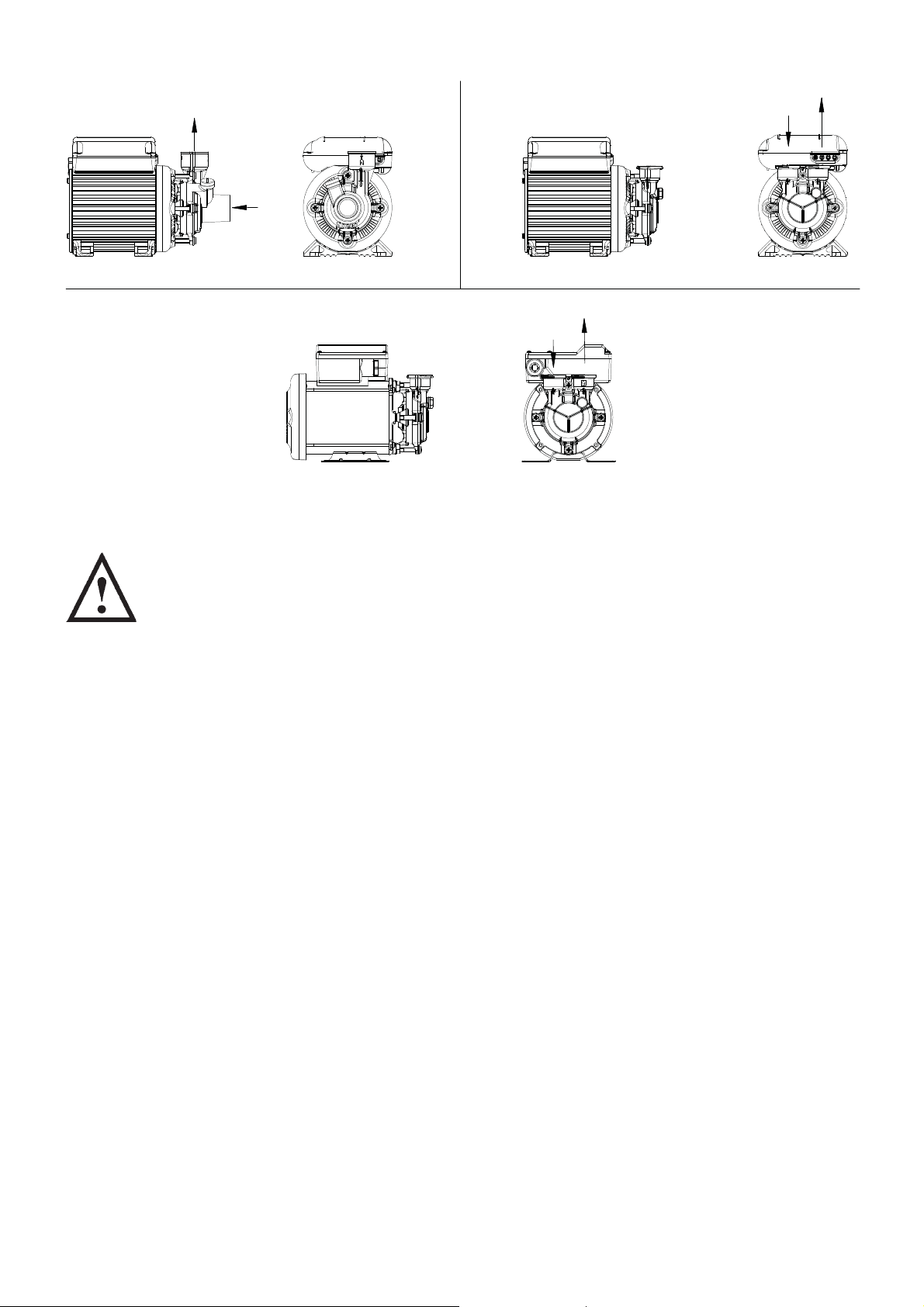
OUTLET
OUTLET
INLET
INLET
Fig. 1
Fig. 3
SITING OF THE PUMP/PIPEWORK
WARNINGS:
Pump Location
If possible site the pump in a location where in the unlikely event of a
liquid leak, any spillage is contained or routed to avoid electrics or
areas sensitive to liquid damage.
Care should be taken to protect the pump from frost and freezing.
Ensure pipework to and from pump is independently supported to
prevent stress on the pump inlet and outlet branches.
Do not fit a non-return valve, or devices which contain non-return
valves, in the suction (inlet) pipework to the pump. Exceptions can
be made in the case of suction lift installations when a footvalve is
required.
When a footvalve is required on installations that incorporate
automatic pump control, it is recommended that a suitable pressure
relief valve be fitted in the discharge (outlet) pipework from the pump.
Do not run against a closed valve for periods longer than 5 minutes.
Do not allow plastic pump parts to come into contact with oil or
cellulose based paints, paint thinners or strippers, acid based
descalents or aggressive cleaning agents.
Do not introduce solder flux to pumps or pump parts manufactured
from plastic. All solder joints should be completed and flux residues
removed prior to pump connection.
The motor casing can become very hot under normal operating
conditions. Care should be taken to ensure it cannot be touched
during operation.
Always install isolating valves to both suction and delivery pipework.
Fig. 2
OUTLET
INLET
Site the pump in a horizontal, dry, frost-free position where it cannot be sprayed with
water and as close to the liquid source as possible.
- 5 -
The pump enclosure must be ventilated and there should be a minimum clearance of
80 mm between the pump and housing on all sides.
To prevent loss of pressure through pipework, use pipe size to match pump whenever
possible, minimising 90° bends.
It must be ensured that storage capacity of the liquid supply is adequate for the flow
rates required by the pump.
The pipework feeds to the storage tank should be of adequate size to ensure
replenishment rate of tank is sufficient to meet the needs of the pump.
Isolating valves should be fitted in suction and delivery pipework to enable easy isolation
and access to the pump.
When the pump is to be installed in areas where there is a risk of debris or scale build up
within the system, it is recommended that the inlet pipework is fitted with an inline strainer.
Pump Mounted Above Liquid Source (Suction Lift)
The pumps can be used in a suction lift installation providing the height of lift is within the
limits specified in the limits of application section.
A footvalve and strainer must always be used and the suction pipework size should be
22 mm throughout.
Lay the suction piping over the shortest possible distance and ensure there is a constant
rise from the liquid source to the pump. Any high spots will cause air pockets to form,
reducing system efficiency.
Ensure all joints in suction pipework are completely airtight. Failure to comply will result
in loss of prime.
The intake of the footvalve/strainer should be positioned such that is cannot be blocked
with debris or silt that are frequently found in the bottom of sumps and wells.
When a footvalve is installed on installations that incorporate automatic pump control,
it is recommended that a suitable pressure relief valve be fitted in the discharge (outlet)
pipework from the pump.
ELECTRICAL INSTALLATION
WARNINGS:
The electrical installation must be carried out in accordance with the
current national electrical regulations by a competent person.
Before starting work on the electrical installation ensure the power
supply is isolated.
Where any of the pumps are installed in an area where there is a risk
of water spillage it is recommended that a residual current circuit
breaker having a rated current not exceeding 30 mA, be installed in
the supply circuit. This may be part of a consumer unit or a separate
unit.
This appliance must be earthed.
The motor and wiring must not be exposed to water.
Do not allow the supply cord to contact hot surfaces, including the
motor shell, pump body or pipework. The cord should be safely
routed and secured by cable clips.
Cont ...
- 6 -
 Loading...