

Installation, Operation & Maintenance
Instructions
Please leave this instruction booklet with the home owner as it contains
important guarantee, maintenance and safety information
Read this manual carefully before commencing installation.
This manual covers the following products:
Monsoon S2.0 bar Single
Pt. No. 46497
Monsoon S3.0 bar Single
Pt. No. 46419
Monsoon S4.5 bar Single
Pt. No. 46420
Monsoon S1.5 bar Twin
Pt. No. 46506
Monsoon S2.0 bar Twin
Pt. No. 46415
Monsoon S3.0 bar Twin
Pt. No. 46416
Monsoon S4.0 bar Twin
Pt. No. 46417
Monsoon S4.5 bar Twin
Pt. No. 46418
FOR POSITIVE HEAD APPLICATIONS ONLY
CE compliant product

PRODUCT DESCRIPTION
Electric motor driven single or twin ended peripheral pump, complete with an automatic
control system, consisting of flow switches and electronic controls.
APPLICATION
Monsoon Standard pumps are suitable for positive head installation conditions. The
pumps are designed for pressure boosting applications in vented stored hot or cold, clean
fresh water systems, where under gravity, some flow (approx. 0.6 l/min) is available. Inlet
pressures to the pump and ambient temperatures must not exceed the values given in the
technical specifications.
Monsoon Standard Single pumps are not suitable for boosting a single side of a dual flow
mixer valve or tap. Consult Stuart Turner for alternative pump.
This pump set must not be used for any other
application without the written consent of Stuart
Turner Limited and in particular, must not be
connected directly to the mains water supply.
This appliance can be used by children aged from
8 years and above and persons with reduced
physical, sensory or mental capabilities or lack
of experience and knowledge if they have been
given supervision or instruction concerning use of
the appliance in a safe way and understand the
hazards involved. Children shall not play with the
appliance. Cleaning and user maintenance shall not
be made by children without supervision.
Children should be supervised to ensure that they do
not play with the appliance.
Please read installation details carefully as they are intended to ensure this product
provides long, trouble free service. Failure to install the unit in accordance with the
installation instructions will lead to invalidation of the warranty.
STORAGE
If this product is not to be installed immediately on receipt, ensure that it is stored in a dry,
frost and vibration free location in its original packaging.
CONTENTS Page
Checklist . . . . . . . . . . . . . . . . . . . . . . . . . . . . . . . . . . . . . . . . . . . . . . . . . . . . . . . . . . . . . . . . 3
Important Facts - read before commencing installation . . . . . . . . . . . . . . . . . . . . . . . . . . . . 4
Location . . . . . . . . . . . . . . . . . . . . . . . . . . . . . . . . . . . . . . . . . . . . . . . . . . . . . . . . . . . . . . . . 5
Pump Connections . . . . . . . . . . . . . . . . . . . . . . . . . . . . . . . . . . . . . . . . . . . . . . . . . . . . . . . . 9
Electrical Installation . . . . . . . . . . . . . . . . . . . . . . . . . . . . . . . . . . . . . . . . . . . . . . . . . . . . . . . 12
Commissioning . . . . . . . . . . . . . . . . . . . . . . . . . . . . . . . . . . . . . . . . . . . . . . . . . . . . . . . . . . . 15
Maintenance . . . . . . . . . . . . . . . . . . . . . . . . . . . . . . . . . . . . . . . . . . . . . . . . . . . . . . . . . . . . . 16
Technical Specifi cation . . . . . . . . . . . . . . . . . . . . . . . . . . . . . . . . . . . . . . . . . . . . . . . . . . . . . 18
Trouble Shooting . . . . . . . . . . . . . . . . . . . . . . . . . . . . . . . . . . . . . . . . . . . . . . . . . . . . . . . . . 20
Guarantee . . . . . . . . . . . . . . . . . . . . . . . . . . . . . . . . . . . . . . . . . . . . . . . . . . . . . . . . . . . . . . . 22
- 2 -
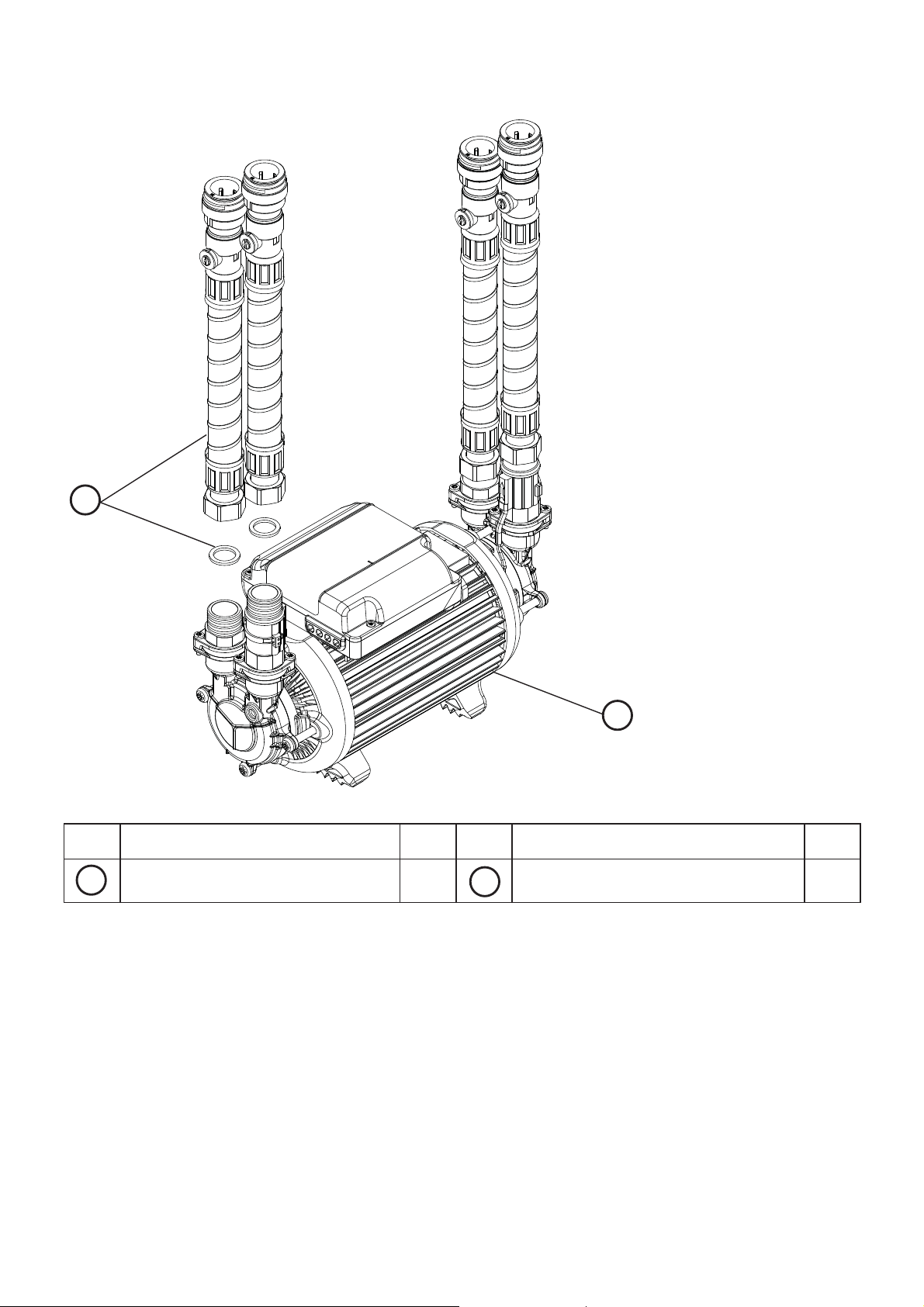
CHECKLIST
B
IMPORTANT: With the pump
removed from its packaging
check for any damage prior to
installation. If any damage is
found contact Stuart Turner Ltd
within 24 hours of receipt.
A
Fig. 1
Item
Your product may vary slightly from the picture above.
The quantities shown above are for twin pumps, (single pumps are shown in brackets).
Description Qty
A
Pump 1 Hose & sealing washer 4 (2)
Item
B
Description Qty
- 3 -
Cont ...

1 READ BEFORE COMMENCING PUMP INSTALLATION
A. Water storage capacity.
1.11 The hot and cold water storage capacity must be sufficient to meet the flow rates
required by the pumped equipment and any other water using fittings and
appliances, which may be operated simultaneously.
1.12 Ensure the pump is primed as described in the priming section before starting,
damage to the shaft seal will result otherwise. See Section 5 - Commissioning.
B. Water temperature
The water entering the pump must be controlled as follows:
o
o
C.
C.
1.13 The maximum allowable water temperature is 65
1.14 The minimum allowable water temperature is 4
1.15 DO NOT fit a pump if the hot water is heated via a method whereby the water
temperature cannot be controlled, such as solar or solid fuel you must consult the
PumpAssist team on 0844 98 000 97.
C. Minimum Flow
1.16 For this pump to operate correctly there must be a minimum gravity flow of at
least 0.6 l/min through all outlets to be pumped.
D. Pipework - General
1.17 Secure pipework: Ensure pipework to and from pump is independently
supported & clipped to prevent forces being transferred to inlet and outlet
branches of pump.
1.18 Flux: Solder joints must be completed and flux residues removed prior to pump
installation (flux damage will void any warranty).
1.19 Pipework design: Care should be taken in the design of pipework runs to
minimize the risk of air locks e.g. use drawn bends rather than 90
o
bends.
1.20 DO NOT introduce solder flux to flexible hoses, pumps or pump parts
manufactured from plastic.
1.21 DO NOT allow contact with oil or cellulose based paints, paint thinners or
strippers, acid based descalents or aggressive cleaning agents.
1.22 DO NOT install a non-return valve, or devices which contain non-return
valves, in the suction (inlet) pipework to the pump. The pump must be free
to vent to the supply tank at all times.
o
1.23 DO NOT bend the flexible hoses beyond 30
. They must be installed as
straight as possible.
1.24 DO NOT connect this pump to the mains water supply.
E. Plumbing & Electrical Installation Regulations
1.25 The plumbing installation must comply with “The Water Supply (Water Fittings)
Regulations 1999” and “BS 6700” building regulations.
1.26 The plumbing installation must be installed by a qualified person.
1.27 The electrical installation must be carried out in accordance with the current
national electrical regulations.
1.28 The electrical installation must be installed by a qualified person.
- 4 -
Cont ...

2 LOCATION - GENERAL
2.11 Access: For emergencies and maintenance the pump must be
easily accessible.
2.12 Protection: The pump must be located in a dry position, frost free and
protected from freezing, particularly when installed in a loft (not
recommended).
2.13 Ventilation: Ensure an adequate air flow to cool the pump. Separate
the pump from other appliances that generate heat. An 80 mm (3 “) air
gap must be maintained around the pump.
2.14 Safety: The motor casing can become very hot under normal
operating conditions. Care must be taken to ensure it cannot be
touched during operation.
2.15 Water retention: Site the pump in a location where in the unlikely
event of a water leak, any spillage is contained or routed to avoid
electrics or areas sensitive to water damage.
2.16 Static inlet pressure: Before deciding where to locate the unit check to ensure
the static inlet head between pump and cold water level (Figs. 4 or 5) is at least
0.5 metres and does not exceed the max inlet head of 14 metres.
2.17 Pump position: The pump must be positioned on its anti-vibration mounting feet
and as close to the water source as possible.
2.18 Ambient temperature: The pump must be sited in a location where the maximum
ambient temperature does not exceed 40
2.19 Pipework: For optimum performance pipework MUST be 22 mm.
Pipework should only reduce to 15 mm when entering terminal fitting.
2.20 Static outlet pressure: The static outlet head (Figs. 4 or 5) must also be within
the maximum requirement of 14 metres.
2.21 Noise: The anti-vibration mounting feet and flexible hoses which are supplied
as standard, and a precaution to reduce noise transmission, however care must
be taken when mounting the pump that any noise is not amplified through loose
panels or pipework. Do not screw down the pump.
2.22 Direction of flow: Ensure the water flow is in the direction of the arrow marked
on the flow switch reed clamp (vertically upwards).
2.23 Flexible hoses: Use only Stuart Turner supplied hoses.
2.24 Isolating valves: Separate isolating valves (non restrictive) must be fitted to
allow easy pump service.
2.25 Preferred pump location: The preferred pump location is at floor level next to
the water source or a level that is below the secondary tapping that feeds
the pump. The Pump location is also dependent on limitations of the static inlet
and outlet heads of the installation. For guidance on limitations and
recommended location, consult the following relevant section for hot or cold water
installation.
o
C.
- 5 -
Cont ...
2.26 Non-Preferred Pump Location: The pump must be located with at least
0.5 metres flooded suction at all times.
If it is not possible to locate the pump in the preferred area due to site limitations
and it is necessary to position the unit in the loft, or in a position above the
secondary tapping that feeds the pump, then there is an increased risk of air
locks. This risk must be eliminated.
The following method will help to overcome the problem:
A “U” bend or downward loop in the supply pipe to the pump of 350 mm depth
before rising to the pump should ensure the cylinder vents its air up the
expansion pipe, not up the pump feed (Fig. 2 for Twins and Fig. 3 for Singles).
200 mm
Max. inlet head 14 m
Min. inlet head 0.5 m
min
Max. inlet head 14 m
Min. inlet head 0.5 m
200 mm
min
hot water
services
Fig. 2 (Twin Pump)
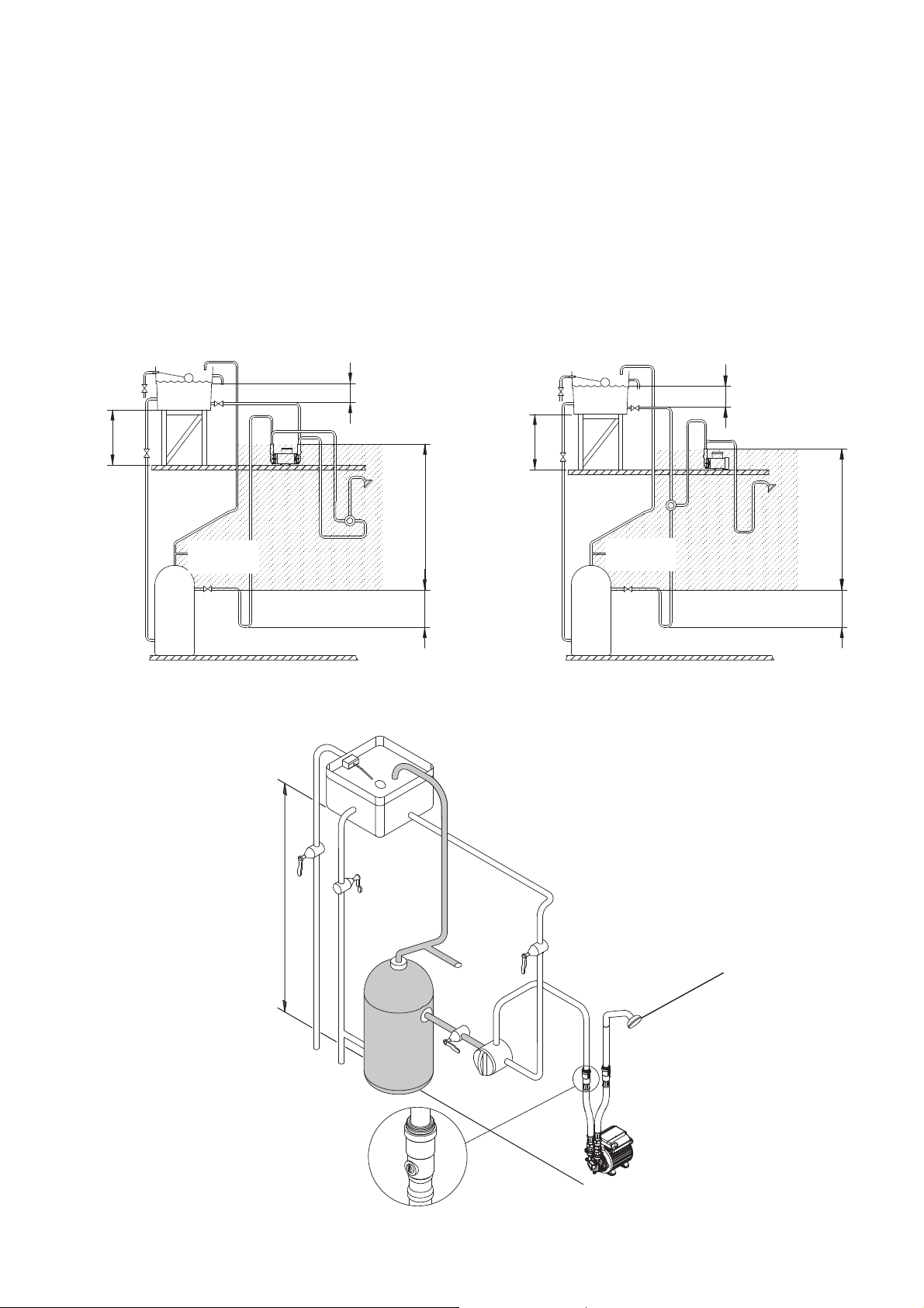
2 LOCATION - SINGLE PUMP
Max. static inlet pressure 14 m
least preferred area
350 mm
min
hot water
services
Fig. 3 (Single Pump)
Outlet head must be
below bottom of cold
water tank and able
to pass a minimum
of 0.6 l/min of gravity
flow
least preferred area
350 mm
min
Positive Duty Single Pump System
Fig. 4
Cont ...
- 6 -
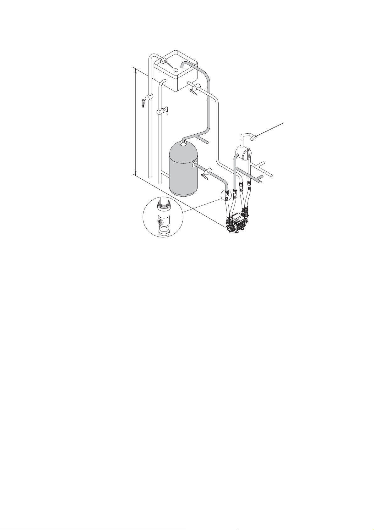
2 LOCATION - TWIN PUMP
Max. static inlet pressure 14 m
Outlet head must be
below bottom of cold
water tank and able
to pass a minimum
of 0.6 l/min of gravity
flow
Positive Duty Twin Pump System
Fig. 5
Cold water connection:
2.27 The cold water supply: Must be a DEDICATED AIR FREE supply via a tank
connector , and must be positioned at a slightly lower level (25 mm minimum) than
the feed pipe to the hot water cylinder.
Do not connect to the mains.
2.28 Location: The pump must, for optimum performance, be sited as close as
possible to and never more than 4 metres from the HOT WATER cylinder. The
pump should always be sited BELOW the HOT WATER take-off from the cylinder.
- 7 -
Cont ...
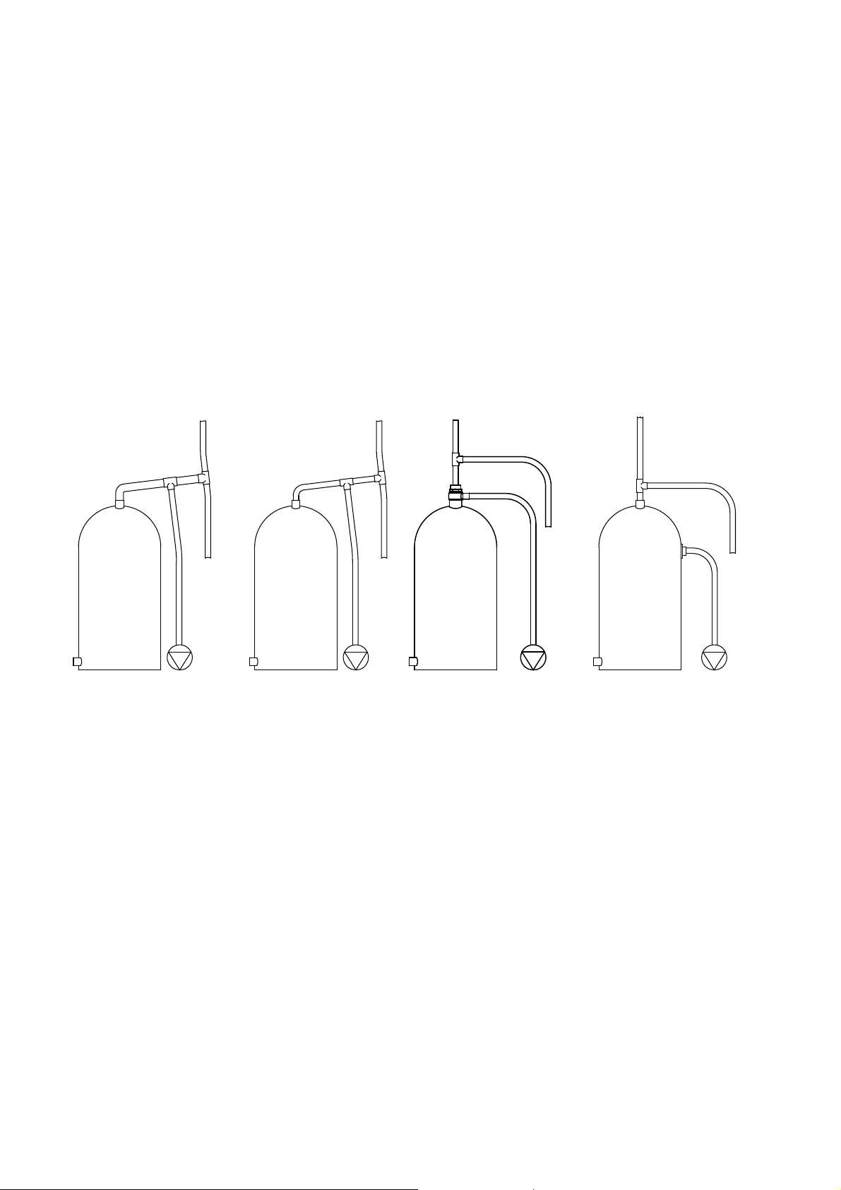
Hot water connection:
(Applicable to S1.5, S2.0, S3.0 and S4.0 bar Twins, S2.0, S3.0 and S4.5 bar Singles)
2. 29 Hot water cylinder or storage tank: When a hot water cylinder or storage tank
is used, ensure the pipework size from the cold water storage to the hot water
storage is of adequate size and a minimum of 22 mm for all models except the
S4.5 bar twin which should be a minimum of 28 mm.
2.30 Hot water supply: The pump must be supplied with a dedicated feed direct
from the hot water cylinder or storage tank, ensuring an air free connection to the
cylinder, which can be made by one of the methods shown in Fig. 6 .
recommend the use of the Stuart flange top entry (TE) Part No 27800
We
(for all
models except the S4.5 bar Twin) (S4.5 bar Twin should only use ‘a’ or ‘d’).
2.31 Expansion pipe: When the method of connection is to be made via the
expansion pipe, the BASE of the cold water storage tank MUST be at least
1 metre above the connection/take off of the hot water storage cylinder feeding
the pump.
Fig. 6
ab
Off expansion
pipe with rising
28 mm offset
reducing to
22 mm pipework
to pump and
expansion pipe.
Off expansion
pipe with rising
22 mm offset
and 22 mm
pipework to
pump.
c
G 1 Stuart flange
top entry (TE) (Part
No. 27800) with 22
mm pipework to
pump.
d
Factory installed G ¾
secondary tapping with
22 mm pipework to
pump.
or
Side mounted Stuart
flange side entry (SE)
(Part No. 27900) with
22 mm pipework to
pump.
- 8 -
Cont ...

3 PUMP CONNECTIONS
Do not use stainless steel, chrome or nickel plated pipe with the
flexible hose push-in plumbing connections.
Do not introduce solder flux into the joint or surrounding area as
connectors will be attacked and may fail.
All solder joints should be completed and flux residues removed
before final connection to push-in connections, on the flexible hose.
Do not allow contact with oil or cellulose based paints, paint
thinners or strippers, acid based descalents or aggressive cleaning
agents.
Never operate pump with inlet and/or outlet isolating valves in the
closed position. Damage will occur!
3.11 Hose to pump: The pump inlet and outlet ports have factory assembled fittings
which are specifically designed for connection to the G ¾ female running nuts on
the flexible hoses. The hose end is fitted with a rubber sealing washer which is
held captive within the nut assembly. Locate the hose into position and
screw the nut fully onto the fitting by hand. Finally nip tight with a spanner
(4/5 Nm) for a water tight seal (do not overtighten).
Flexible hose
Fig. 7
G ¾ running nut
assembly
Rubber sealing washer
Port fitting
29 mm AF
Reed
switch
clamp
assembly
Anti-rotation flats
28 mm AF
Note: When tightening or loosening the
hose nut assembly, the anti-rotation
flats provided on the inlet and outlet
fittings should be used for placement
of a second spanner as shown. This is
to prevent complete assembly rotation.
It may be necessary to partially rotate
the reed switch clamp assembly on the
outlet fitting to avoid damage during
placement of the second spanner.
- 9 -
Cont ...

3.12 Hose to pipework:
1. The hoses are fitted with plastic push-in connectors, which must only be
connected with the following:
a) 22 mm diameter copper pipe to BS EN 1057 - R250 (half hard) - Table 3.
b) 22 mm plastic pipe to BS 7291 part 1 and part 2 (Table 1), or part 3
(Table 1) plus internal support sleeve*.
* The internal bore of the plastic pipe must be supported against collapse
with the pipe manufacturers recommended support sleeve (pipe insert).
c) Appropriate plumbing fittings that are compatible and will provide a water
tight connection.
Ensure the pipe is free from all score marks and deformities in the area of the
insertion depth (Fig. 8) and cut the pipe square removing all burrs and sharp
edges to prevent damage to the sealing ‘O’-ring.
2. Prior to inserting pipe into fitting mark the insertion depth on the wall of the
pipe with a soft pencil at a distance of 33 mm from the end to be inserted.
Pencil
mark
33 mm
Insert depth
22 mm Pipe
Fig. 8
3. Check in the mouth of the fitting that ‘O’-ring, nylon washer and collet are in
position.
Body
Collet
Washer
‘O’-Ring
Pipe Stop
Hose
Fig. 9
Isolating Valve
4. Push pipe firmly into fitting, until pencil mark is level with the top of the collet
and the pipe stop resistance is felt. Pull on pipe to check it is secure and
correctly fitted.
Cont ...
- 10 -

5. To break the joint, push pipe firmly into fitting, hold collet down and gently
remove pipe. If the system has been filled with water care should be taken to
isolate pump and towels used to absorb spilled water.
3.13 Typical Low Level Installation:
In certain installations it may be necessary to install a 90° bend on the inlet
or outlet connections of the pump before the flexible hose to accommodate a low
level installation.
Below are some preferred connection options. All connections seal on the pump
body using a fibre or rubber sealing washer. Tap connector fittings should be
used which must be of an appropriate pressure and temperature rating.
It is essential when using any of the fittings shown below, that a correct water tight
seal is obtained between the pump body and selected fitting and also the
flexible hose and selected fitting. If in doubt contact the fitting manufacturer and
confirm compatibility with the connection to be sealed.
Carefully check connections and pipework for leaks whilst pump running and
stationary before leaving the installation unattended.
G ¾ female x 22 mm
elbow tap connector.
Fibre washer.
22 mm
elbow.
22 mm
copper
pipe
Fig. 10
22 mm compression to
G ¾ male.
22 mm copper pipe.
G ¾ female x 22 mm
tap connector.
Fibre washer.
G ¾ female flexible hose
(supplied in kit).
G ¾ female flexible hose
(supplied in kit).
22 mm compression to
G ¾ male.
G ¾ female x 22 mm
swivel tap connector
with rubber sealing
washer.
22 mm to G ¾
male.
22 mm stem elbow.
G ¾ female x 22 mm tap
connector with rubber
sealing washer.
Sealing washer (sometimes
captured in fitting)
G ¾ female
flexible hose
(supplied in
kit).
If you have any concern either about using push-in fittings or should the joint
leak on final test isolate the water supplies and contact PumpAssist on
0844 98 000 97.
Cont ...
- 11 -

4 ELECTRICAL INSTALLATION / EARTHING
4.11 Regulations: The electrical installation must be carried out in
accordance with the current national electrical regulations and installed
by a qualified person.
4.12 Safety: In the interests of electrical safety a 30 mA residual current
device (R.C.D. not supplied) should be installed in the supply circuit.
This may be part of a consumer unit or a separate unit.
4.13 Before starting work on the electrical supply ensure power supply is
isolated.
4.14 DO NOT allow the supply cord to contact hot surfaces, including the
motor shell, pump body or pipework. The cord should be safely routed
and secured by cable clips.
4.15 Adjacent pipes: Adjacent suction and delivery pipes should be fitted with
earthing clamps to BS 951 and connected with earthing wire size 4 mm
Diagram of
earth continuity
connections
2
(Fig. 11).
Fig. 11
4.16 Earthing: This appliance must be earthed via the supply cord, which must be
correctly connected to the earth point located in the terminal box.
4.17 Pipework: Copper or metallic pipework must have supplementary earth bonding
where the continuity has been broken by flexible hoses or plastic components.
4.18 Additional earthing: Certain installations may require additional earthing
arrangements such as equipotential bonding. Reference should be made to the
relevant regulations concerning this subject to ensure compliance.
4.19 Connections: The pump must be permanently connected to the fixed wiring of
the mains supply using the factory fitted supply cord, via a double pole switched
fused spur off the ring main and NOT connected to the boiler or the immersion
heater circuits.
4.20 Wiring of connection unit:
WARNING: This appliance must be earthed.
The wires in the mains lead are coloured in accordance with the following code:
Green and Yellow: Earth Blue: Neutral Brown: Live
As the colours of the wires in the mains lead of this appliance may not correspond
with the coloured markings identifying the terminals in your connection unit
proceed as follows:
The wire which is coloured green and yellow must be connected to the terminal
in the connection unit which is marked with the letter E or by the earth symbol:
or coloured green or green and yellow.
- 12 -
Cont ...

The wire which is coloured blue must be connected to the terminal which is
marked with the letter N or coloured black.
The wire which is coloured brown must be connected to the terminal which is
marked with the letter L or coloured red.
4.21 Wiring Diagrams:
Parallel wiring of two single pumps is not recommended.
S1
MAIN WINDING
THERMOTRIP
START WINDING
L
N
BLUE
BROWN
GREEN/
YELLOW
RED
CAPACITOR
BLACK
N
230 VAC/1PH/50Hz
L
SUPPLY
E
FLOWSWITCH REED (S2)
FLOWSWITCH REED (S1)
BROWN
LINK WIRE (BLUE)
N
MA
S1S2S2
N
S1
Single Models
Fig. 12
MAIN WINDING
THERMOTRIP
START WINDING
L
BLUE
BROWN
GREEN/
YELLOW
RED
CAPACITOR
BLACK
N
230 VAC/1PH/50Hz
L
SUPPLY
E
FLOWSWITCH REED (S2)
BROWN
LINK WIRE (BLUE)
N
MA
S1S2S2
Twin Models
Fig. 13
4.22 Fuses: The following fuse size should be used with the appropriate pump:
Model Fuse Size (AMPS)
S4.0 bar Twin
13
S4.5 bar Twin
All other models 5
4.23 Supply Cord Replacement:
The supply cord and internal wiring within the terminal box are
routed and secured to ensure compliance with the electrical
standard EN 60335-1. It is essential that prior to any disturbance
of this internal wiring, all cable routing and securing details are
carefully noted to ensure re-assembly to the same factory pattern
is always maintained.
If the supply cord is to be changed or is damaged, it must be replaced with a
special cord assembly available from Stuart Turner or one of their approved
repairers.
On disassembly note the cord retention and routing system. Re-assemble to the
same pattern.
For information on cable connection consult the wiring diagram and cable gland
fitting instructions.
- 13 -

4.24 Cable Gland Fitting Instructions:
1
2
Fig. 14
To enable correct assembly of the cable gland the ‘O’-ring (Fig. 14 item 1) must
be placed over the cable before the clamping insert (Fig. 14 item 2) can be
tightened.
Note: Cable diameter range:- 6.5 mm to 9.5 mm.
4.25 Supply Cord Extension:
The pumps are fitted with a supply cord to the following specification:-
All models . . . . . . . . . . . . . . . . . . HO5VV-F3 G 0.75 mm² - 6 Amp rated cable.
If the supply cord is to be extended, a cord of the same specification should
be used. Any connections or junction boxes used should be specifically suited for
the application and installed in accordance with the manufacturers instructions.
- 14 -
Cont ...

5 COMMISSIONING
5.11 System Flushing: This pump incorporates push-in connectors
and plastic components that must not come into contact with
solder flux, acid-based descalents or aggressive cleaning agents.
The pipework system should be flushed out prior to the pump
being connected to ensure any contaminants/chemical residues
and foreign bodies are removed from elsewhere in the system.
5.12 Water Supply: Always ensure that water storage capacity is adequate to meet
the demand. Ensure the pump chamber is full of water before starting the pump.
Failure to do this could result in seal damage. To ensure dry running does not
occur the pump must be primed as described in priming section below.
Do not run pump dry.
5.13 Priming:
Never operate pump with inlet and/or outlet isolating valves in the
closed position. Damage will occur!
The pump must be primed (filled with water) before starting. Turn on water
supply from the system service valves, prime and vent the pump by opening the
pump inlet and outlet isolating valves to allow pump to fill and vent.
In the case of twin pumps, both pump chambers must be independently primed.
5.14 Starting:
a) Ensure all outlets are closed, turn power supply ‘on’ - pump will start,
pressurise the system then stop.
b) Open and close all outlets in turn associated with the pump, (including w/c
systems) allowing water to flow from each outlet until all air is purged. As
each outlet is opened and closed, the pump will start and stop respectively.
Note: After closing the outlet there will be a small time delay before the pump
stops, which is normal.
c) Any tap or control valve within the system when opened and closed will now
turn the pump on/off. Providing this is the case the system is now operating
correctly.
d) Carefully check pump and pipework for leaks whilst pump running and
stationary before leaving the installation unattended.
5.15 For Further Technical Support: Phone the Stuart Turner PumpAssist team
on 0844 98 000 97. Our staff are trained to help and advise you over the phone.
- 15 -
Cont ...

6 MAINTENANCE
6.11 Turn off water supplies to the pump and release pressure by
opening water outlets before attempting maintenance.
6.12 Inlet strainer: The inlet strainers may require periodical cleaning. The frequency
of this operation is dependent upon installation conditions.
The strainer is located in the inlet assembly of the pump casing (Fig. 15) and is
removed as follows: a) Isolate pump electrically.
b) Release all system pressure.
c) Isolate hot and cold water supplies via the integral pump isolating valve
located in the flexible hoses and release hose nuts connected to the pump
(see Section 3 - Pump Connections).
d) Remove M4 screws (2 off) from inlet assembly, lift brass inlet fitting (with ‘O’-
ring) and clamp away from pump casing (Fig. 15).
e) Remove strainer with long nose pliers noting location lug position upon
removal (Fig. 15) and clean thoroughly.
f) Refit strainer taking care to position lug in body inlet port location slot (Fig. 15)
and re-assemble pipework. Tighten M4 clamp screws to 1.5 Nm torque.
g) Re-connect flexible hoses and tighten (see Section 3 - Pump Connections).
h) After maintenance is completed refer to Section 5 - Commissioning section for
instructions on re-starting pump.
Inlet fitting
Inlet port
M4 screws
Manifold clamp
‘O’-ring
Strainer
Fig. 15
- 16 -
Location detail
Cont ...

6.13 No other routine maintenance is required.
6.14 Water scale: As water is heated scale deposits are released in areas of hard
water, scale can cause the mechanical seal to stick if left without use for long
periods. The pump must be run for at least 5 minutes every four weeks to
“exercise” all working parts. Run on cool water. See Section 7 - Technical
Specification for note on water temperature. This particularly applies to guest
bathrooms used infrequently.
6.15 Cleaners, Disinfectants and Descalents:
Acid based descalents and aggressive cleaning agents must not
come into contact with the pump. The pump must be removed from
the system prior to the use of these products. The system should be
flushed to remove all chemicals before the pump is re-connected.
If in any doubt as to the suitability of the chemical solutions, please
contact our PumpAssist helpline.
- 17 -
Cont ...

7 TECHNICAL SPECIFICATION (Single Models)
Model S2.0 bar Single S3.0 bar Single S4.5 bar Single
Power supply
Volts/phase freqency
Enclosure IPX4 IPX4 IPX4
Type of motor Induction Induction Induction
Power consumption 245 Watts 385 Watts 555 Watts
Electrical
Full load current 1.1 Amps 1.7 Amps 2.4 Amps
Rating
Max. No Starts per hour 60 60 60
Max inlet head 8 metres 14 metres 14 metres
Max head (closed valve) 20 metres 30 metres 45 metres
Max working pressure* 600 kPa (6.0 bar) 600 kPa (6.0 bar) 600 kPa (6.0 bar)
Max ambient air temperature 40
Mechanical
Max water temperature** 65
Min water temperature 4
230/1/50 230/1/50 230/1/50
Continuous (S1) @
9 l/min & above
o
C 40 oC 40 oC
o
C 65 oC 65 oC
o
C4
Continuous (S1) @
9 l/min & above
o
C4
Continuous (S1) @
9 l/min & above
o
C
Length 200 mm 200 mm 200 mm
Width 126 mm 126 mm 126 mm
Height (excluding flexible hoses) 202 mm 202 mm 202 mm
Weight (incl. flexible hoses) 6.5 Kg 6.5 Kg 7.1 Kg
Pump
Dimensions
Pump connections: Inlet G ¾ G ¾ G ¾
Outlet G ¾ G ¾ G ¾
- 18 -
Cont ...

7 TECHNICAL SPECIFICATION (Twin Models)
Model
Power supply
Volts/phase freqency
Enclosure IPX4 IPX4 IPX4 IPX4 IPX4
Type of motor Induction Induction Induction Induction Induction
Power consumption 345 Watts 425 Watts 640 Watts 890 Watts 1090 Watts
Full load current 1.5 Amps 1.9 Amps 2.8 Amps 4.0 Amps 4.9 Amps
Electrical
Rating
Max. No Starts per hour 60 60 60 60 60
Max inlet head 14 metres 14 metres 14 metres 14 metres 14 metres
Max head (closed valve) 15 metres 20 metres 30 metres 42 metres 45 metres
Max working pressure*
Max ambient air temperature 40
Mechanical
Max water temperature** 65
S1.5 bar
Twin
230/1/50 230/1/50 230/1/50 230/1/50 230/1/50
Continuous
(S1) @ 9 l/min
& above (Both
ends pumping)
600 kPa
(6.0 bar)
o
C 40 oC 40 oC 40 oC 40 oC
o
C 65 oC 65 oC 65 oC 65 oC
S2.0 bar
Twin
Continuous
(S1) @ 9 l/min
& above (Both
ends pumping)
600 kPa
(6.0 bar)
S3.0 bar
Twin
Continuous
(S1) @ 9 l/min
& above (Both
ends pumping)
600 kPa
(6.0 bar)
S4.0 bar
Twin
Continuous
(S1) @ 9 l/min
& above (Both
ends pumping)
600 kPa
(6.0 bar)
S4.5 bar
Twin
Continuous
(S1) @ 9 l/min
& above (Both
ends pumping)
600 kPa
(6.0 bar)
o
Min water temperature 4
Length 265 mm 265 mm 265 mm 300 mm 310 mm
Width 126 mm 126 mm 126 mm 126 mm 126 mm
Height (excluding flexible hoses) 202 mm 202 mm 202 mm 202 mm 202 mm
Weight (incl. flexible hoses) 8.4 Kg 8.4 Kg 8.7 Kg 10.7 Kg 11.4 Kg
Pump
Dimensions
Pump connections: Inlet G ¾ G ¾ G ¾ G ¾ G ¾
Outlet G ¾ G ¾ G ¾ G ¾ G ¾
C4
o
C4
o
C4
o
C4
o
C
Stuart Turner reserve the right to amend the specification in line with its policy of
continuous development of its products.
Note: For information on other voltages/frequencies which are not shown, consult
any supplementary instruction sheet supplied, or the rating label attached to
the pump.
*Note: Max working pressure is the maximum pressure that can be applied to the
pump internal casing under any installation conditions.
**Note: In normal circumstances the temperature of stored water should never exceed
65°C. A stored water temperature of 60°C is considered sufficient to meet all
normal requirements and will minimise deposition of scale in hard water
areas.
Maximum permissible water temperature 65°C.
7.11 Noise: The equivalent continuous A-weighted sound pressure level at a distance
of 1 metre from the pump does not exceed 70 dB(A).
- 19 -

8 TROUBLE SHOOTING GUIDE
Symptoms Probable Cause Recommended Action
Pump will not start. Insufficient gravity flow. Check flow rate minimum of 0.6 l/min required on full hot and
cold.
Electrical. Check power supply.
Check fuse (see fuse section).
Check circuit breaker is set.
Check wiring connections.
Pump jammed. If motor ‘Buzzes’ switch off power and contact Stuart Turner.
Integral motor thermotrip
activated.
Reduced/intermittent flow. Incorrect or no anti-aeration
flange fitted.
Incorrect pipe sizes. Check for correct pipe sizing, see Page 8 - Section 2.29.
Blocked inlet filters. Clean inlet filters (see maintenance section).
Air in system. Run system on full hot with pump switched off (ie. gravity
Hot water temperature set to
high.
Blocked shower head spray
plate.
No hot water. Air locked water feed. Vent hot water pump of air.
Heating source not operating. Check boiler is switched ‘on’.
Wait for thermotrip to auto-reset and check that duty point and
run time is within specification (see technical specification).
Check that the installation complies with installation
instructions.
only) for several minutes. Check that vents are fitted as
detailed in instructions.
Reduce cylinder stat setting to 65
Clean in accordance with manufacturers instructions.
Check cold feed to hot water cylinder.
Check water level in cold water tank and that all stopcocks
and isolating valves are open.
Check cylinder thermostat.
Check immersion heater.
Check cylinder contains hot water.
o
C max.
All hot water has been used. Check tank volume is adequate.
Faulty thermostatic mixer valve. Consult makers instructions.
Pump runs on with outlets
closed.
Pump starts with all outlets
closed.
Flexible hose leaks Not fitted correctly. Check that the hose is pushed firmly onto the pump inlet/
Jammed flow switch. Remove outlet hoses and check that flow switch sits in lowest
position. Check float for free movement.
Damaged reed switch or P.C.B. If pump continues to run, this indicates a closed circuit in
either the flow switch reed or P.C.B. in the terminal box.
Contact Stuart Turner.
Leak in system. Check tap washers, w/c valve washers, pipe joints.
Air in system. Bleed through system without pump running until hot and cold
services run with no air.
outlet connections and pipework.
Damaged ‘O’-rings. Check copper pipe ends are cleanly cut and deburred.
Cont ...
- 20 -

8.11 Flow Switch Circuit Test:
1. First confirm visually that the flow switch reed clamps have not been
dislodged during handling or installation. The clamps must be fully located
within their flow switch body groove as shown.
2. To carry out the following test you will need to obtain a magnet, a typical fridge
magnet is suitable.
3. Ensure the power supply is switched on.
4. Position the magnet directly in front of the reed clamp as shown. If pump
does not start, then slowly move the magnet up and down to a position that
exceeds the extent of the reed clamp. The pump should instantaneously start
at some point during this extent of movement. If this does not happen, this
indicates a possible fault with the reed switch or the P.C.B which is located
within the terminal box. These should be checked electrically. Consult Stuart
Turner for further instructions.
Body
Reed Clamp
Groove
Fig. 16
Magnet
8.12 Environment Protection: Your appliance contains valuable materials which can
be recovered or recycled.
At the end of the products’ useful life, please leave it at an appropriate local civic
waste collection point.
- 21 -
Cont ...

9 THE MONSOON GUARANTEE
Congratulations on purchasing a Stuart Turner pump.
We are confident this pump will provide many years of trouble free service as all our
products are manufactured to the very highest standard.
All Monsoon Pumps are guaranteed to be free from defects in materials or
workmanship for 3 years from the date of purchase.
EXTEND YOUR PUMP GUARANTEE
Register your pump details on-line now (within 30 days of date of purchase) and the
standard 3 year guarantee will be extended FREE of charge for a further two years.
www.stuart-turner.co.uk
If you do not have on-line access or would like us to help you register your pump then
simply call our ‘PumpAssist’ helpline on 0844 98 000 97.
Please note that to validate your extended warranty we will require the following
information:
1. Full pump serial number (including last 3 digits) which can be found on the pump
rating label and the back page of the installation instructions.
2. Your name/address/telephone/e-mail.
3. The date of installation.
Within the guarantee period we will repair, free of charge, any defects in the pump
resulting from faults in material or workmanship, repairing or exchanging the whole unit
as we may reasonably decide.
Not covered by this guarantee: Damage arising from incorrect installation, improper
use, unauthorised repair, normal wear and tear and defects which have a negligible
effect on the value or operation of the pump.
Reasonable evidence must be supplied that the product has been purchased within
the guarantee term prior to the date of claim (such as proof of purchase or the pump
serial number).
This guarantee is in addition to your statutory rights as a consumer. If you are in any
doubt as to these rights, please contact your local Trading Standards Department.
Cont ...
- 22 -

In the event of a claim please telephone ‘PumpAssist’ or return the pump and flexible
hoses with the accessories removed e.g pipes etc. If you have any doubt about
removing a pump, please consult a professional.
0844 98 000 97
Proof of purchase should accompany the returned unit to avoid delay in investigation
and dealing with your claim.
You should obtain appropriate insurance cover for any loss or damage which is not
covered by Stuart Turner Ltd in this provision.
Please record here for your records.
TYPE NO. SERIAL NO. DATE PURCHASED
Installers – Register with Stuart Turner and move up to Approved
Installer status
We receive thousands of enquiries every month from people seeking a Stuart
Turner installer and by registering your details with us, we can offer consumers the
opportunity to quickly locate an installer in their area.
Registration is free - simply click on the ‘register as an installer’ link on
our homepage at www.stuart-turner.co.uk and complete a short form
which will enable visitors to find your contact details on our web site
‘installer finder’. Alternatively use your smartphone to scan this QR code
and go straight to the form.
We’ll do the rest!
In addition we will ensure you receive advance notice on all new product launches and
access to any special offers or promotions.
Following initial registration, Stuart Turner offers a professional training programme,
enabling you to achieve Approved Installer status and opening the door to a range of
additional benefits.
Contact approvedinstaller@stuart-turner.co.uk for further details.
- 23 -

DECLARATION OF CONFORMITY
2006/42/EC
BS EN ISO 12100-1, BS EN ISO 12100-2, BS EN 809
2006/95/EC
BS EN 60335-1, BS EN 60335-2-41
2004/108/EC
BS EN 55014-1, BS EN 55014-2, BS EN 55022, BS EN 61000-3-2, BS EN 61000-3-3,
BS EN 61000-4-2, BS EN 61000-4-3, BS EN 61000-4-4, BS EN 61000-4-5, BS EN 61000-4-6,
BS EN 61000-4-11
1999/519/EC
BS EN 62233
2011/65/EU
IT IS HEREBY CERTIFIED THAT THE STUART ELECTRIC MOTOR DRIVEN PUMP AS
SERIAL NUMBER BELOW, COMPLIES WITH THE ESSENTIAL REQUIREMENTS OF THE
ABOVE E.E.C. DIRECTIVES.
RESPONSIBLE PERSON
AND MANUFACTURER STUART TURNER LIMITED
HENLEY-ON-THAMES, OXFORDSHIRE
RG9 2AD ENGLAND.
Signed . . . . . . . . . . . . . . . . . . . . . . . . . . . . . . . . . . . . . . . . .
Stuart Turner are an approved company to BS EN ISO 9001:2000
Business Development Director
Stuart Turner Ltd, Henley-on-Thames, Oxfordshire RG9 2AD ENGLAND
Tel: +44 (0) 1491 572655, Fax: +44 (0) 1491 573704
info@stpumps.co.uk www.stuart-turner.co.uk
V.A.T. REG. No. 199 0987 92. Registered in England No. 88368. Registered Offi ce: Market Place, Henley-on-Thames
Issue No. 1614/2-01 Pt. No. 19227
 Loading...