

Stuart Turner Monsoon Extra U3.0 bar Single User Manual
Installation Instructions
For Monsoon Extra
Universal Single Duty Pump
Medium Pressure U1.4 bar High Pressure U3.0 bar
High Pressure U3.5 bar High Pressure U4.5 bar
INDEX . . . . . . . . . . . . . . . . Page No
Application . . . . . . . . . . . . . . . . . . . . . . . . 1
Storage . . . . . . . . . . . . . . . . . . . . . . . . . . 1
Typical Installation . . . . . . . . . . . . . . . . . . 2
Pre-Installation Assembly . . . . . . . . . . . . 2
Pump Location. . . . . . . . . . . . . . . . . . . . . 4
Pipework Connections . . . . . . . . . . . . . . . 6
Pump Connections . . . . . . . . . . . . . . . . . 9
INDEX . . . . . . . . . . . . . . . . Page No
Electrical Installation . . . . . . . . . . . . . . . . 12
Commissioning . . . . . . . . . . . . . . . . . . . . 14
Maintenance . . . . . . . . . . . . . . . . . . . . . . 16
Technical Specifi cation . . . . . . . . . . . . . . 18
Noise . . . . . . . . . . . . . . . . . . . . . . . . . . . . 19
Trouble Shooting Guide . . . . . . . . . . . . . . 19
Environment Protection . . . . . . . . . . . . . . 21
PRODUCT DESCRIPTION
Electric motor driven centrifugal pump complete with an automatic control system,
consisting of flow switch, pressure switch, pressure vessel and electronic control.
APPLICATION
The Monsoon Extra Universal Single range is designed for pressure boosting
applications in vented stored, hot or cold, clean water systems, where under gravity, no
flow is available. Inlet pressures to the pump and ambient temperatures must not exceed
the values given in the technical specifications.
This pump set must not be used for any other application without the
written consent of Stuart Turner Limited and in particular, must not be
connected directly to the mains water supply.
This appliance is not intended for use by persons (including children)
with reduced physical, sensory or mental capabilities, or lack of
experience and knowledge, unless they have been given supervision
or instruction concerning use of the appliance by a person responsible
for their safety.
Children should be supervised to ensure that they do not play with the
appliance.
This product should not be used for the supply of water to more than
one dwelling (house, apartment, flat).
STORAGE
If this product is not to be installed immediately on receipt, ensure that it is stored in a
dry, frost and vibration free location in its original packaging.
Please leave this instruction booklet with the pump as it
contains maintenance and safety information (Original Instructions)
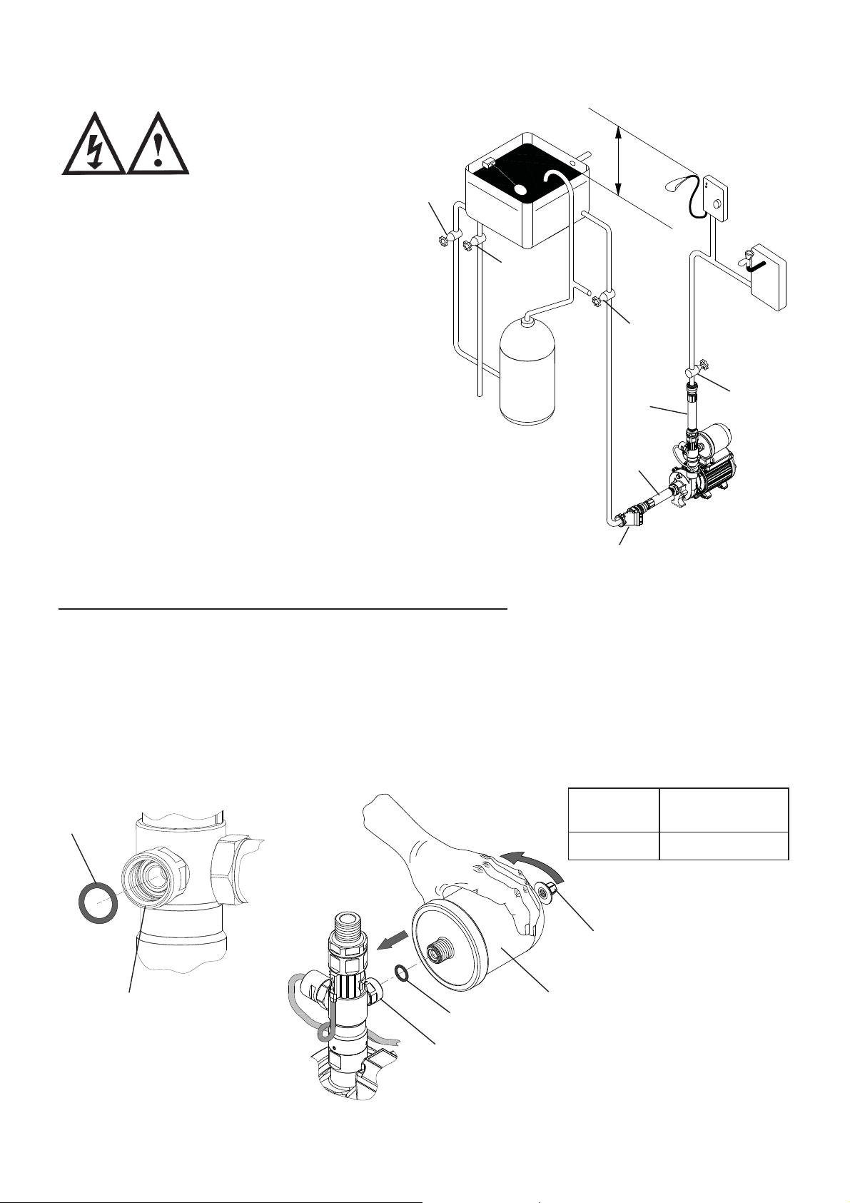
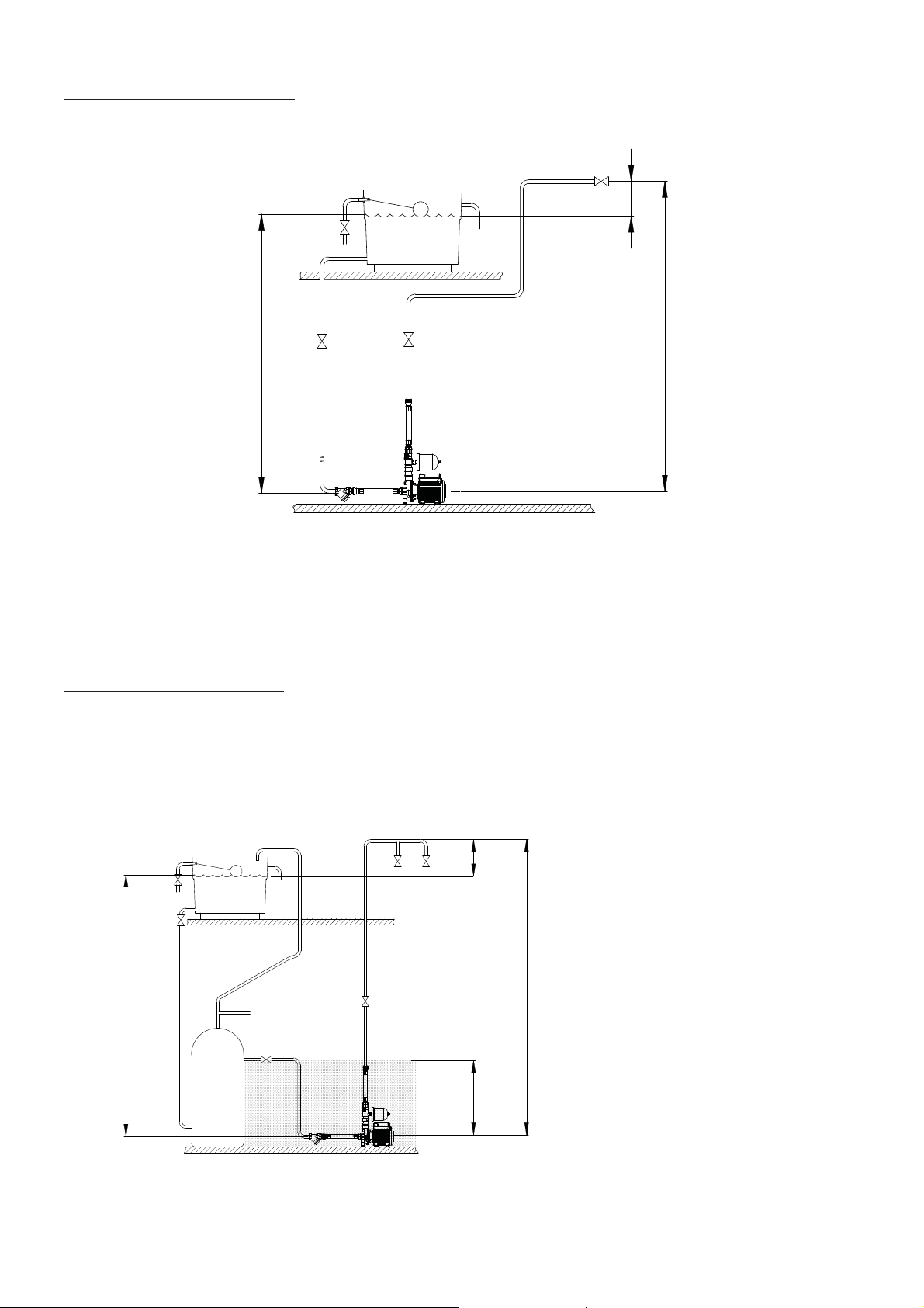
TYPICAL INSTALLATION (Cold Water, Universal Duty, Single Pump System)
The plumbing installation
must comply with the
following:
The Water Supply (Water Fittings)
Regulations 1999.
BS6700 and building regulations.
Be installed by a competent person.
If in doubt contact Stuart Turner Ltd
This diagram should be used for
schematic reference only
1: Isolating valve (not supplied)
2: Inlet strainer
3: Flexible hose
1
1
1
1
3
3
Fig. 1
2
STEP 1: PRE-INSTALLATION ASSEMBLY
Pressure Check and Assembly of Pressure Vessel
a) Certain models are is supplied in two parts, the main pump and the pressure vessel.
The pressure vessel is pre-charged with air at the factory (see table below). This
pressure should be checked at the Schrader valve (Fig. 2) using a tyre pressure
gauge and adjusted if necessary using a car or bicycle pump prior to installation.
b) To assemble the vessel (when applicable), remove protective plastic cap from fitting
point. Ensure that the ‘O’-ring is present and correctly fitted in the location groove at
the bottom of the fitting point. Screw the pressure vessel clockwise into the fitting
point until hand tight to achieve a water tight connection.
Air Precharge
bar (psi)
‘O’-Ring
Model
All Models 0.9 (13)
Schrader valve
(under cap)
Detail view of
‘O’-Ring groove
in fitting point
Pressure vessel
‘O’-Ring
Fitting point
Fig. 2
NOTE: Do not over tighten pressure vessel.
- 2 -
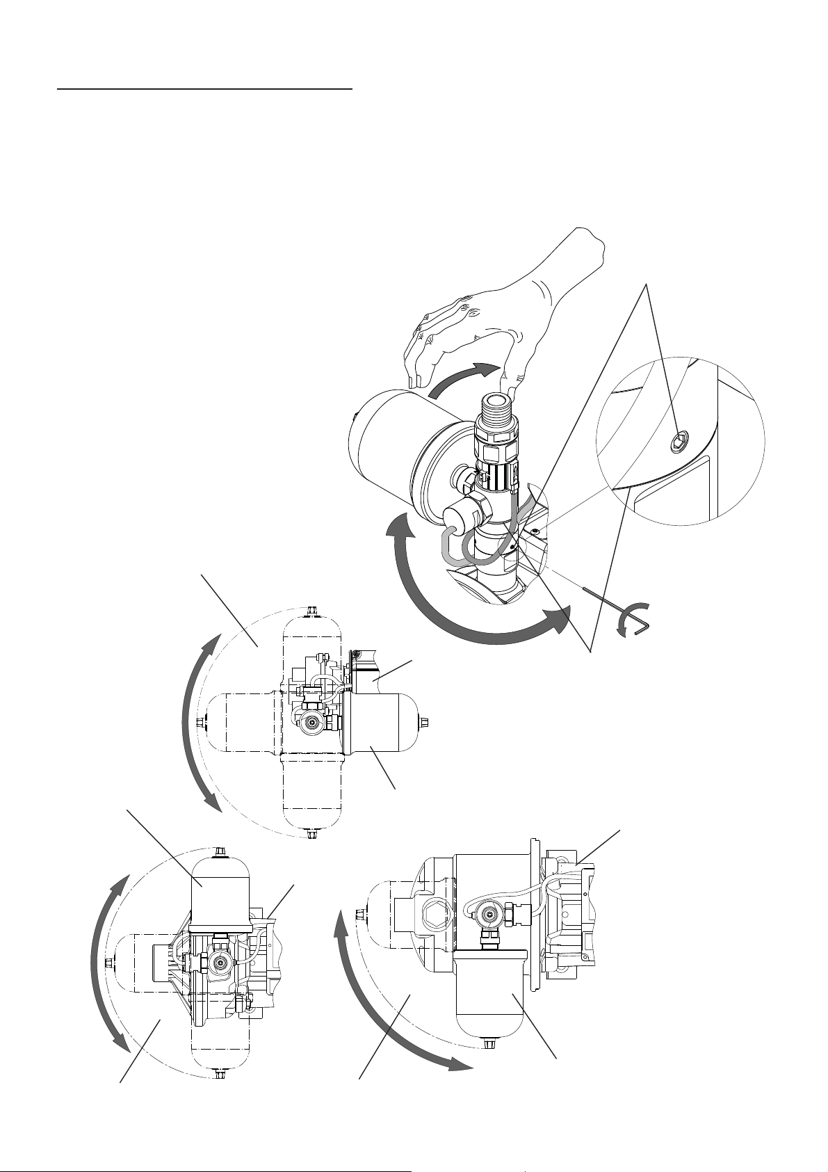
Re-positioning of Pressure Vessel
The pressure vessel can be rotated to alternative positions (Figs. 4, 5 & 6) in the event of
the factory fitted position being unsuitable for a specific installation.
a) Remove pressure vessel by unscrewing anti-clockwise.
b) Using a 2 mm allen key, carefully loosen all three retaining grub screws by two
turns (Fig. 3).
c) Warning - Care must be taken when re-positioning the pressure vessel to
ensure no strain is placed upon the pressure
switch or reed switch cables.
The flow switch assembly can now be carefully
rotated to an alternative position
(Figs. 4, 5 & 6).
d) Ensure all three grub screws are
re-tightened securely to a torque of
2.2 Nm (1.62 lbf feet).
e) Re-fit the pressure vessel
ensuring the ‘O’-ring seal is
in place (see pre-installation
section).
Grub Screws
(3 off)
Area for alternative fitting positions
Factory fitted position
U3.0 bar, U3.5 bar
Fig. 5
Fig. 4
Motor
Motor
Factory fitted position
U1.4 bar
Fig. 6
Fig. 3
Outlet Tower can be swivelled at
this joint line after loosening the
3 equi-spaced grub screws
Motor
Area for alternative fitting positions Area for alternative fitting positions
- 3 -
Factory fitted position
U4.5 bar
STEP 2 PUMP LOCATION (General)
WARNINGS:
Pump Location
If possible site the pump in a location where in the unlikely event of a
water leak, any spillage is contained or routed to avoid electrics or
areas sensitive to water damage.
Care should be taken to protect pump from frost and freezing,
particularly when located in a loft installation.
The motor casing can become very hot under normal operating
conditions, care should be taken to ensure it cannot be touched
during operation.
Locate the pump in a dry, frost free position where it cannot be sprayed with water. It
should be positioned horizontally on its anti-vibration mounting feet and should not be
screwed down. It should be positioned as close to the water source as possible having a
minimum flooded suction head of 1 metre at all times.
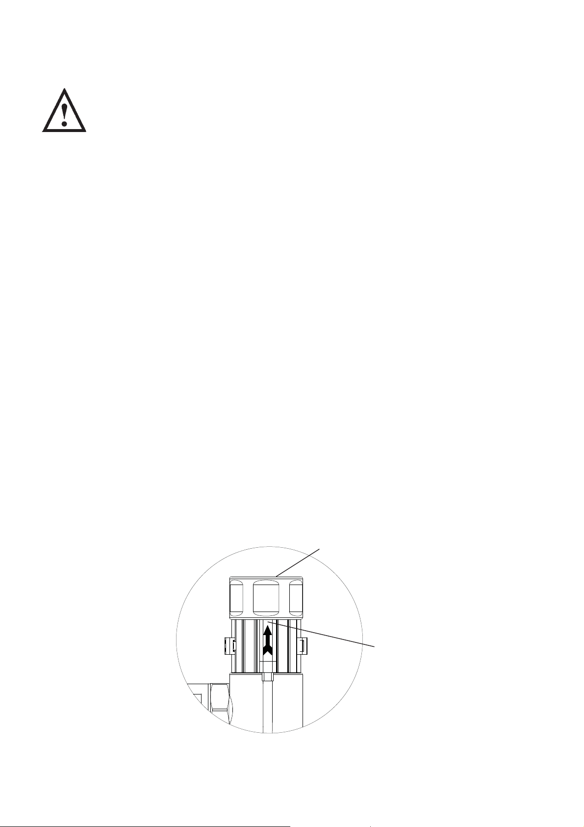
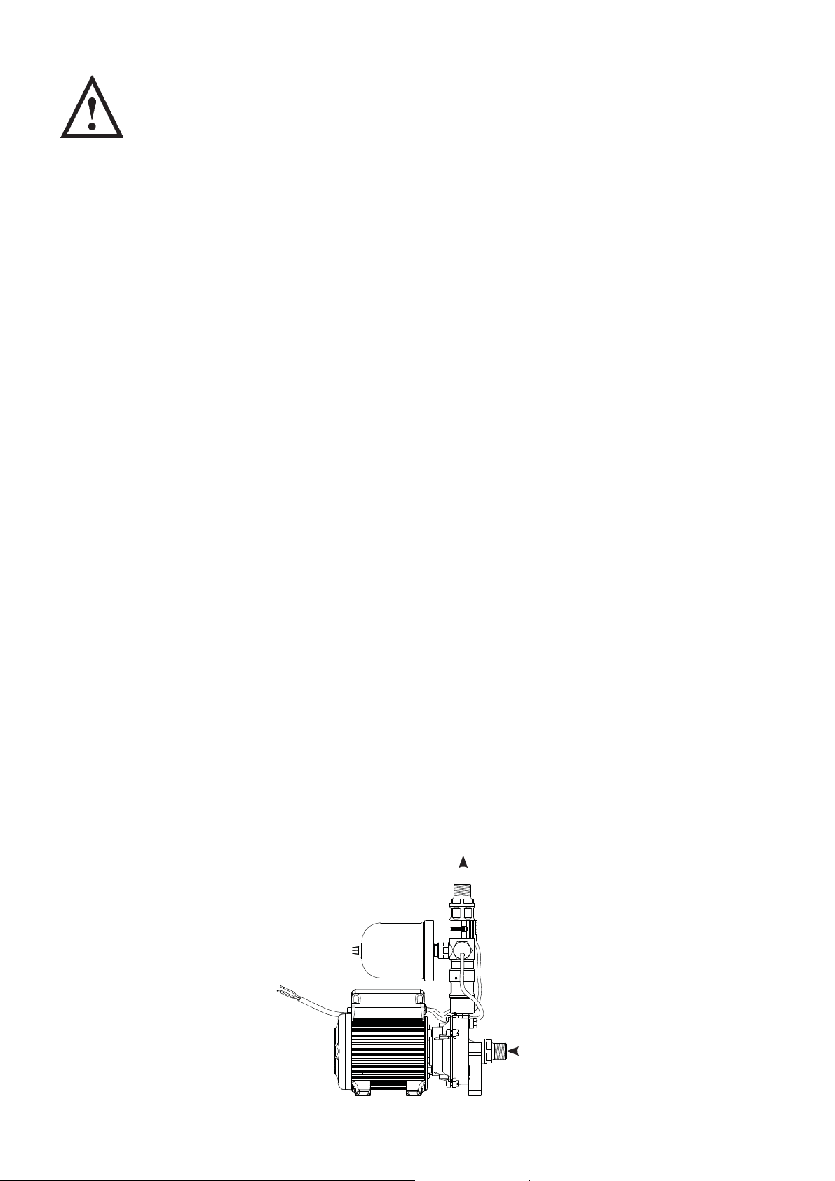
Ensure the water flow is in the direction of the arrow that is marked on the flow switch
reed clamp (vertically upwards) (Fig. 7).
Typical pump locations are in an airing cupboard, or inside a vanity unit with a small
purpose built dry and ventilated enclosure. The enclosure should have a minimum
clearance of 80 mm (3 ”) between the pump and housing on all sides. The enclosure
should be secure and access should only be available by the use of tools.
The resilient anti-vibration mounting feet and flexible hoses which are supplied as
standard, are a precaution to reduce noise transmission, however care must be taken
when mounting the pump that any noise is not amplified through loose panels, pipework or
other mounting medium.
The preferred pump location is at floor level next to the hot water cylinder or a level that
is below the secondary tapping that feeds the pump. This will ensure the pump has access
to an air free water supply which is important for trouble free operation (Figs. 8 & 9).
Pump location is also dependent on limitations of the static inlet and outlet heads of the
installation. For guidance on limitations and recommended location, consult the following
relevant section for hot or cold water installation.
Fig. 7
Outlet
Flow must be in
direction of flow
switch arrow
(vertically upwards)
Cont ...
- 4 -
Cold Water Installations
Max. inlet head 10 m ( 8 m for U1.4)
Min. inlet head 1 m
Negative
head
Max. outlet head 13 m ( 8 m for U1.4)
Fig. 8
Before deciding where to locate the unit, check to ensure the static inlet head (Fig. 8)
meets the minimum requirement of 1 metre and does not exceed the maximum
requirement of 8 metres for U1.4 and 10 metres for other models.
The static outlet head (Fig. 8) must also be within the maximum requirement of 8 metres
for U1.4 and 13 metres for other models.
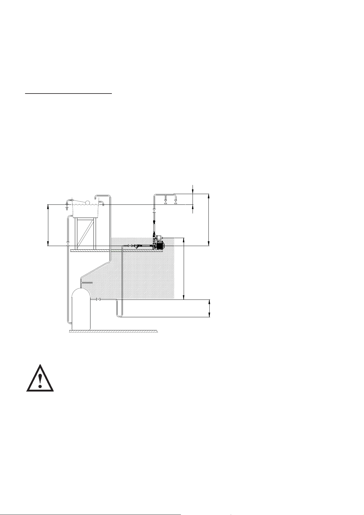
Hot Water Installations
The preferred pump location is at floor level next to the hot water cylinder or a level that
is below the secondary tapping that feeds the pump. This will ensure the pump has access
to an air free water supply which is important for trouble free operation (Fig. 9).
Negative
head
Preferred Pump Location
(shaded area). Pump at
a level below the cylinder
draw off tapping.
Max. inlet head 10 m ( 8 m for U1.4)
Min. inlet head 1 m
- 5 -
Preferred
area
Max. outlet head 13 m ( 8 m for U1.4)
Fig. 9
Cont ...
Before deciding where to locate the unit, check to ensure the static inlet head (Fig. 9)
meets the minimum requirement of 1 metre and does not exceed the maximum
requirement of 8 metres for U1.4 and 10 metres for other models.
The static outlet head (Fig. 9) must also be within the maximum requirement of 8 metres
for U1.4 and 13 metres for other models.
Hot Water Installations
If it is not possible to locate the pump in the preferred area due to site limitations and it is
necessary to position the unit in the loft, or in a position above the secondary tapping that
feeds the pump, then there is an increased risk of air locks. This risk must be eliminated.
The following measure is a suggestion that may overcome the problem:
A “U” bend or downward loop in the supply pipe to the pump of 350 mm depth before
rising to the pump should ensure the cylinder vents its air up the expansion pipe, not up the
pump feed (Fig. 10).
Negative
head
Max. inlet head 10 m ( 8 m for U1.4)
Min. inlet head 1 m
Least preferred area
STEP 3 PIPEWORK CONNECTIONS (General)
WARNINGS
Ensure pipework to and from pump is independently supported to
prevent forces being transferred to inlet and outlet branches of pump.
Do not introduce solder flux to pumps or pump parts manufactured
from plastic. All solder joints should be completed and flux residues
removed prior to pump connection.
Do not allow contact with oil or cellulose based paints, paint thinners
or strippers, acid based descalents or aggressive cleaning agents.
Always install isolating valves to both suction and delivery pipework.
Max. outlet head 13 m ( 8 m for U1.4)
350 mm
min.
Fig. 10
Least Preferred Pump
Location (shaded area).
Pump located above the
hot cylinder can increase
the risk of air locks.
- 6 -
Cont ...
Do not install a non-return valve, or devices
which contain non-return valves, in the
suction (inlet) pipework to the pump. The
pump must be free to vent to the supply
tanks at all times.
It must be ensured that the water storage capacity is sufficient to meet the flow rates
required by the pump and any other water using fittings and appliances, which may be
operated simultaneously.
As a rule of thumb: assuming a cold water temperature of 10°C and a hot water
temperature of 65°C.
A 6-minute shower using 10 litres/min will consume 40 litres of hot water and 20 litres
of cold. This means the total quantity of water used from the cold water storage tank
will be 60 litres (40 + 20).
A 10-minute shower using 15 litres/min will consume 100 litres of hot water and 50
litres of cold. This means the total quantity of water used from the cold water storage
tank will be 150 litres (100 + 50).
On installations where there are high flow requirements e.g. multiple showers or body
jets.
A 10-minute shower using 45 litres/min will consume 300 litres of hot water and 150
litres of cold. This means the total quantity of water used from the cold water storage
tank will be 450 litres (300 + 150).
The pipework feeds to the storage tank should be of adequate size to ensure
replenishment rate of tanks is sufficient to meet the needs of the pump.
Care should be taken in the design of pipework runs, to minimize the risk of airlocks.
To prevent loss of water pressure through pipework use 28 mm suction pipework to the
pump.
Any bend requirements should be achieved by hand drawing the tube or by use of the
appropriate bend fittings. All pipework should be securely clipped.
Isolating valves (not supplied) should be fitted on the suction and delivery pipework to
enable easy isolation and access to the pump.
The 1 “ inline strainer as supplied should be fitted in the suction line to the pump
between the isolating valve and the pump. This will eliminate the risk of debris or scale
entering the pump.
Outlet
Fig. 11
U1.4 Single shown
Inlet
Cont ...
- 7 -
Pipework Connections (Cold)
The pump must be supplied with a dedicated feed direct from the cold water
storage tank.
Ensure the pipework size from the cold water storage tank to the pump is of adequate
size and a minimum of 28 mm.
The supply must be air free and connections of the feed pipe to the tank should be via a
tank connector, positioned at a slightly lower level (25 mm minimum) than the feed pipe to
the hot water cylinder.
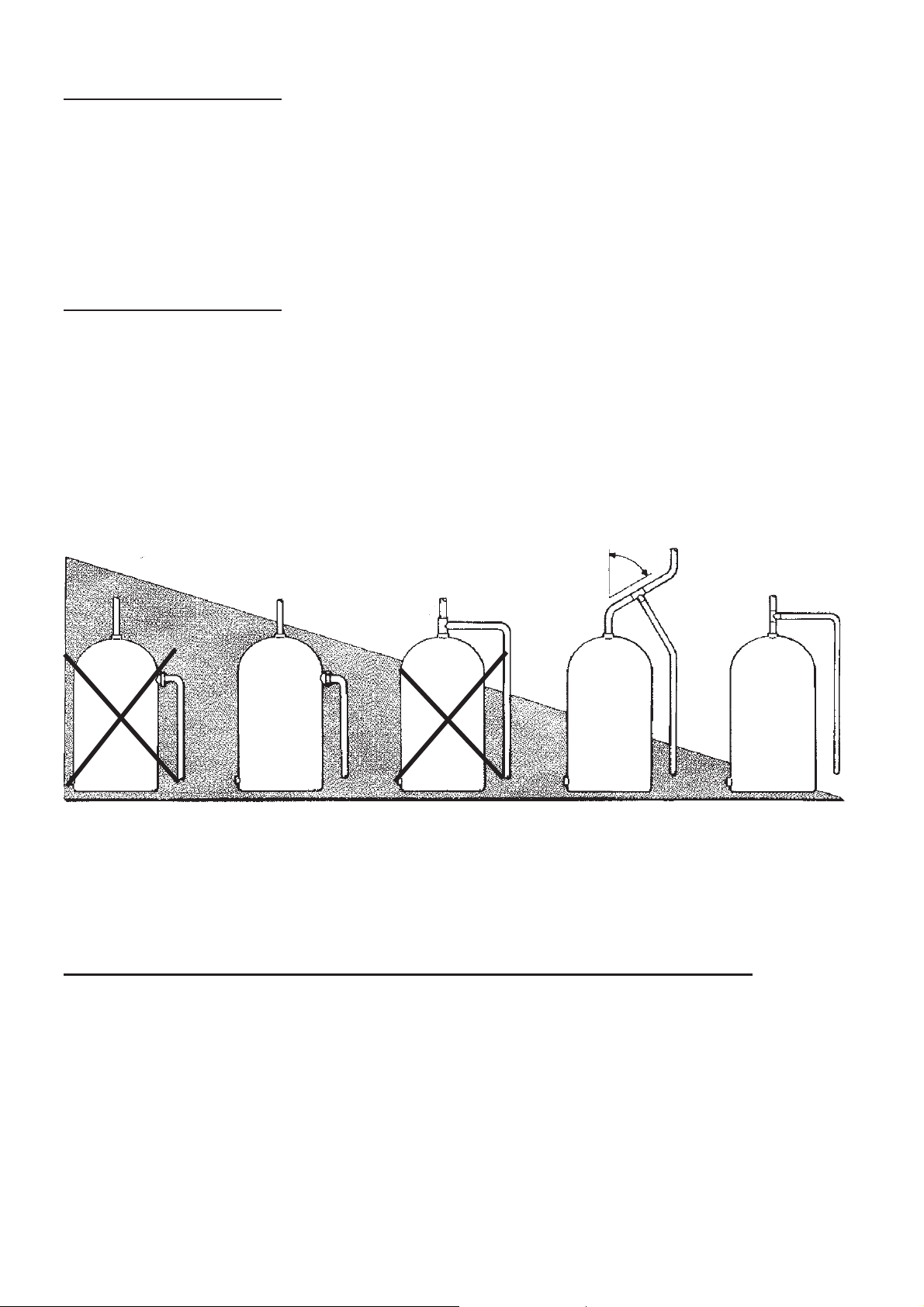
Pipework Connections (Hot)
When a hot water cylinder or storage tank is used, ensure the pipework size from the
cold water storage to the hot water storage is of adequate size and a minimum of 28 mm.
The pump must be supplied with a dedicated feed direct from the hot water
cylinder or storage tank.
Ensure the pipework size from the hot water storage tank to the pump is of adequate
size and a minimum of 28 mm. The supply must be air free and connection to the cylinder
can be via an Essex flange, or by one of the methods shown in Fig. 12.
When the method of connection is to be made via the expansion pipe, the cold water
cistern should be at least 1.5 metres above the top of the hot water cylinder.
Most preferred
Existing
secondary
tappings
22 mm
NOT RECC
Essex
flange
28 mm
Fig. 12
Surrey
flange
22 mm outlet
NOT RECC
Least
45°
Off expansion
pipe, off-set 45°,
28 mm pipework
(As close to the cylinder as possible)
preferred
Off vertical
expansion
pipe 28 mm
pipework
Pipework Connections (Connection between pump and system outlets)
This should run as far as possible in 22 mm copper tube. Any bend requirements should
be achieved by hand drawing the tube or by use of the appropriate bend fittings. Pipework
should only be reduced to 15 mm copper if necessary when entering the terminal fittings.
By this method the maximum performance of the pump will be maintained. All pipework
should be securely clipped.
- 8 -
Cont ...
 Loading...