

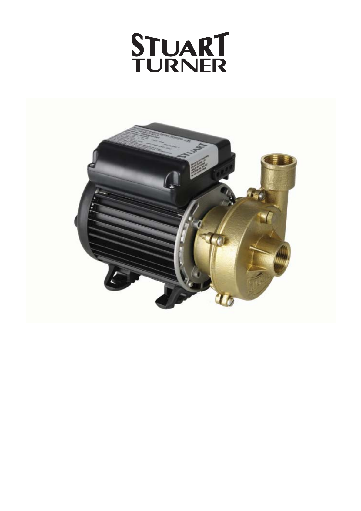
CENTRIFUGAL PUMPS
OPERATING INSTRUCTIONS
Please leave this instruction booklet with the pump as it
contains maintenance and safety information
(Original Instructions)
MODELS
Kennet K7-2
Kennet K9-2
Thame T6-2
Thame T12-2
Loddon L5-4S
Loddon L7-4S
Kennet K12-2
INDEX . . . . . . . . . . . . . . . . . Page No
Application . . . . . . . . . . . . . . . . . . . . . . . . . 2
Product Description . . . . . . . . . . . . . . . . . . 3
Limits of Application . . . . . . . . . . . . . . . . . . 3
Technical Specifi cation . . . . . . . . . . . . . . . 4
Connections . . . . . . . . . . . . . . . . . . . . . . . 5
Siting of the Pump/Pipework . . . . . . . . . . . 6
Electrical Installation . . . . . . . . . . . . . . . . . 8
IMPORTANT NOTES
Please read these instructions fully before starting the
installation:
The installation must comply with the relevant water supply,
electrical and building regulations and be installed by a
competent person.
If in doubt, consult Stuart Turner Ltd.
X201
INDEX . . . . . . . . . . . . . . . . . Page No
Noise . . . . . . . . . . . . . . . . . . . . . . . . . . . . . 13
Commissioning . . . . . . . . . . . . . . . . . . . . . 13
Maintenance . . . . . . . . . . . . . . . . . . . . . . . 15
Trouble Shooting Guide . . . . . . . . . . . . . . . 16
Performance Information . . . . . . . . . . . . . . 17
Environment Protection . . . . . . . . . . . . . . . 17
APPLICATION
The range of centrifugal pumps is designed to pump clean fresh water. Other clean,
non aggressive, non explosive liquids with similar characteristics to water may be pumped.
Consult Stuart Turner for advice on such applications.
The pumps can be used for pressure boosting, fluid transfer and distribution. They are
suitable for flooded suction applications. Alternatively a maximum suction lift of
4.6 metres is permitted when using a Stuart footvalve/strainer.
The X201 pump is a self priming pump. Suction lifts up to 6 metres are possible, with or
without a footvalve/strainer, once the pump is primed.
WARNING AGAINST MISUSE
This pump set must not be used for any other application without the
written consent of Stuart Turner Limited. In particular, it must not be
connected directly to the mains water supply, or used outside the
conditions specified in the limits of application.
This appliance is not intended for use by persons (including children)
with reduced physical, sensory or mental capabilities, or lack of
experience and knowledge, unless they have been given supervision
or instruction concerning use of the appliance by a person responsible
for their safety.
Children should be supervised to ensure that they do not play with the
appliance.
- 2 -
Cont ...

PRODUCT DESCRIPTION
Motor:
Induction type, totally enclosed fan ventilated cooling, continuously rated, class ‘F’
insulation. Motors comply with BS 5000 or IEC 34-1. Single phase versions incorporate
a permanent capacitor and integral auto resetting thermal overload protection. Enclosure
ratings are given in the technical specification section.
The standard range of motors are suitable for a supply of 230V, 1 phase, 50Hz.
Optional motors are available on certain models to suit various voltages and frequencies
(see technical specification for details).
Pump:
Close coupled, end suction configuration and of centrifugal design. The number of
pump stages are given in the technical specification section. Standard pump materials of
construction of major wetted parts are as follows: -
Model Body Impeller Shaft Mechanical Seal
Kennet Range Brass
Thame Range
Loddon
X201 Noryl Glass filled Nylon Brass (Sleeved)
Noryl
Stainless Steel
Noryl
Stainless Steel
Acetal or
Brass
Polycarbonate Stainless Steel
Polycarbonate Stainless Steel
Stainless Steel
Nitrile/Carbon/Silicon
Carbide/Stainless Steel
Nitrile/Carbon/Silicon
Carbide/Stainless Steel
Nitrile/Carbon/Silicon
Carbide/Stainless Steel
Nitrile/Carbon
Ceramic/Stainless Stee
Other seal material options are available on certain models.
LIMITS OF APPLICATION
Model Supply Impeller
Material
K7-2 230/1/50 Plastic 80 4 40 4.6* 9.2 50 9.5 600 (6) 51 60
K9-2 230/1/50 Plastic 80 4 40 4.6* 8.9 50 9.5 600 (6) 51 60
K9-2 230/1/50 Brass 80 4 40 4.6* 9.2 50 9.5 600 (6) 51 60
K9-2 400/3/50 Plastic 80 4 40 4.6* 9 50 9.5 600 (6) 51 60
K12-2 230/1/50 Plastic 80 4 40 4.6* 13.9 50 9.5 600 (6) 51 60
Max.
Liquid
Temp.
o
C
Min.
Liquid
Temp.
o
C
Max.
Ambient
Air Temp
o
C
Max.
Suction
Lift (m)
Max. Head
(Pump
Closed
Valve) (m)
Max. Viscosity
(Redwood
No. 1 Scale)
Centistokes
**Max.
Working
Pressure
kPa (bar)
Max.
Inlet
Head
(m)
Starts/h
Max.
No.
K12-2 230/1/50 Brass 80 4 40 4.6* 14.7 50 9.5 600 (6) 51 60
K12-2 400/3/50 Plastic 80 4 40 4.6* 14 50 9.5 600 (6) 45 60
T6-2 230/1/50 Plastic 65 4 40 4.6* 30 50 9.5 400 (4) 10 60
T12-2 230/1/50 Plastic 65 4 40 4.6* 32 50 9.5 400 (4) 7 60
L5-4S 230/1/50 Plastic 65 4 40 4.6* 47.5 50 9.5 700 (7) 27 60
L7-4S 230/1/50 Plastic 65 4 40 4.6* 49.5 50 9.5 700 (7) 23 60
X201 230/1/50 Plastic 50 4 40 6 19 50 9.5 300 (3) 11 60
* With footvalve fitted.
**Note: Max working pressure is the maximum pressure that can be applied to the
pump internal casing under any installation conditions.
- 3 -

TECHNICAL SPECIFICATION
Model Supply Impeller
Material
K7-2 230/1/50 Plastic 180 230 1 IP44 237 131 180 6.1 1
K9-2 230/1/50 Plastic 250 330 1.5 IP44 242 131 180 6.3 1
K9-2 230/1/50 Brass 250 350 1.6 IP44 242 131 180 6.3 1
K9-2 400/3/50 Plastic 250 370 0.85 IP44 288 133 166.5 6.3 1
K12-2 230/1/50 Plastic 500 595 2.8 IP44 277 131 180 8.2 1
K12-2 230/1/50 Brass 500 635 2.9 IP44 277 131 180 8.2 1
K12-2 400/3/50 Plastic 500 610 1.1 IP44 288 133 166.5 6.3 1
T6-2 230/1/50 Plastic 650 890 3.9 IP55 326 210 214 8.2 2
T12-2 230/1/50 Plastic 820 1140 5.2 IP55 350 210 214 9.4 2
L5-4S 230/1/50 Plastic 600 925 4.1 IP55 400 202 214 9.8 4
L7-4S 230/1/50 Plastic 760 1075 4.9 IP55 424 202 214 10.8 4
X201 230/1/50 Plastic 670 930 4.1 IP55 375 205 255 9.6 1
Nominal
Watts
Output
(Motor)
Max. Watts
consumed
at full flow
Full
Load
(AMPS)
Enc.
Rating
Dims (mm) Gross
Weight
(packed)
LWH
No. of
Pump
Stages
kg
Stuart Turner reserve the right to amend the specification in line with its policy of
continuous development of its products.
Note: For information on other voltages/frequencies which are not shown, consult any
supplementary instruction sheet supplied, or the rating label attached to the
pump.
- 4 -
Cont ...
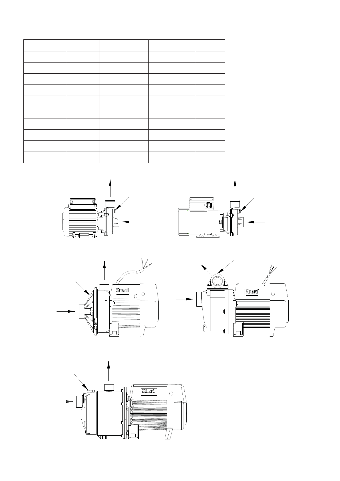
CONNECTIONS
Pump Type Voltage Inlet Outlet Fig. No
K7-2 230/1/50 G1 Female G1 Female 1
K9-2 230/1/50 G1 Female G1 Female 1
K9-2 400/3/50 G1 Female G1 Female 2
K12-2 230/1/50 G1 Female G1 Female 1
K12-2 400/3/50 G1 Female G1 Female 2
T6-2 230/1/50 G1 Female G1 Female 3
T12-2 230/1/50 G1 Female G1 Female 3
L5-4S 230/1/50 G 1¼ Female G1 Female 5
L7-4S 230/1/50 G 1¼ Female G1 Female 5
X201 230/1/50 G 1¼ Female G 1¼ Female 4
PRIMING
PLUG
INLET
Fig. 1
OUTLET
OUTLET
TURNER LTD
Fig. 3
PRIMING
PLUG
INLET
INLET
Fig. 2
OUTLET
OUTLET
PRIMING
PLUG
TURNER LTD
Fig. 4
PRIMING
PLUG
INLET
PRIMING
PLUG
INLET
OUTLET
TURNER LTD
Fig. 5
Cont ...
- 5 -

SITING OF THE PUMP/PIPEWORK
WARNINGS:
Pump Location
If possible site the pump in a location where in the unlikely event of a
liquid leak, any spillage is contained or routed to avoid electrics or
areas sensitive to liquid damage.
Ensure pipework to and from pump is independently supported to
prevent stress on the pump inlet and outlet branches.
Do not fit a non-return valve, or devices which contain non-return
valves, in the suction (inlet) pipework to the pump. Exceptions can
be made in the case of suction lift installations when a footvalve is
required.
When a footvalve is required on installations that incorporate
automatic pump control, it is recommended that a suitable pressure
relief valve be fitted in the discharge (outlet) pipework from the pump.
Do not run against a closed valve for periods longer than 5 minutes.
Do not allow plastic pump parts to come into contact with oil or
cellulose based paints, paint thinners or strippers, acid based
descalents or aggressive cleaning agents.
Do not introduce solder flux to pumps or pump parts manufactured
from plastic. All solder joints should be completed and flux residues
removed prior to pump connection.
Care should be taken to protect the pump from frost and freezing.
Always install isolating valves to both suction and delivery pipework.
The motor casing can become very hot under normal operating
conditions. Care should be taken to ensure it cannot be touched
during operation.
Site the pump horizontally in a dry, frost-free position where it cannot be sprayed with
water and as close to the liquid source as possible.
The pump enclosure must be ventilated and there should be a minimum clearance of
80 mm between the pump and housing on all sides.
To prevent loss of pressure through pipework, use pipe size to match pump whenever
possible, minimising 90° bends.
It must be ensured that storage capacity of the liquid supply is adequate for the flow
rates required by the pump.
The pipework feeds to the storage tank should be of adequate size to ensure
replenishment rate of tank is sufficient to meet the needs of the pump.
Isolating valves should be fitted in suction and delivery pipework to enable easy isolation
and access to the pump.
When the pump is to be installed in areas where there is a risk of debris or scale build up
within the system, it is recommended that the inlet pipework is fitted with an inline strainer.
- 6 -
Cont ...

Mounting Foot Securing
Some pumps within the range are fitted with plastic mounting feet. If there is a
requirement to secure the pump via the mounting feet, the following points should be
noted.
The pump should be mounted only in the horizontal position.
Floor mounting is the preferred
orientation but wall mounting is
possible providing all fixing
holes provided are used.
*Air locking possible. Special care
required to vent the pump casing
of air with this orientation.
The mounting bolts
used to secure the
pump must be fitted
with a plain washer to
distribute clamping
load evenly across
load bearing face of
foot.
MOUNTING
FOOT
PLAIN
WASHER
Fig. 6
BOLT
Fig. 7
Pump Mounted Above Liquid Source (Suction Lift)
The pumps can be used in a suction lift installation providing the height of lift is within the
limits specified in the limits of application section (Fig. 8).
A footvalve and strainer must always be used (except X201 when used on a self priming
installation) and the suction pipework size must match the pump.
Lay the suction piping over the shortest possible distance and ensure there is a constant
rise from the liquid source to the pump. Any high spots will cause air pockets to form,
reducing system efficiency.
Ensure all joints in suction pipework
are completely airtight. Failure to
comply will result in loss of prime.
The intake of the footvalve/strainer
should be positioned such that it cannot
be blocked with debris or silt that are
frequently found in the bottom of sumps
and wells.
Max suction lift (m)
(see Limits of Application
When a footvalve is installed on
installations that incorporate automatic
pump control, it is recommended that a
suitable pressure relief valve be fitted in
the discharge (outlet) pipework from the
pump.
Fig. 8
Section)
Suction lift installation with
footvalve and strainer
- 7 -

ELECTRICAL INSTALLATION
WARNINGS:
The electrical installation must be carried out in accordance with the
current national electrical regulations and installed by a competent
person.
Before starting work on the electrical installation ensure the power
supply is isolated.
Where any of the pumps are installed in an area where there is a risk
of water spillage and particularly in the case of the X201, it is
recommended that a residual current circuit breaker having a rated
current not exceeding 30 mA, be installed in the supply circuit. This
may be part of a consumer unit or a separate unit.
This appliance must be earthed.
The motor and wiring must not be exposed to water.
Do not allow the supply cord to contact hot surfaces, including the
motor shell, pump body or pipework. The cord should be safely
routed and secured by cable clips.
The standard single phase pumps are suitable for a supply of 230V, 1 Phase, 50Hz.
Other voltages and frequencies are available on certain models and it is therefore very
important to ensure the voltage and frequency on the pump rating plate matches the
supply.
When installing a 230V, 1 phase, pump in the United Kingdom, means for disconnection
must be incorporated in the fixed wiring according to the Wiring Rules. This can be done
by permanently connecting the pump to the mains supply via a double pole switched, fused
connection unit complying with BS 1363-4.
The standard three phase pumps are suitable for a supply of 400V, 3 Phase, 50Hz and
should be connected via a starter complete with suitably sized thermal overload.
All motors exceeding 370 watt output should be provided with control equipment
incorporating means for protection against overload.
The spur box (fused connection unit) or starter to which the pump is connected should
be mounted in an easily accessible position and labelled if confusion is possible to allow
easy isolation of the unit.
All pumps are continuously rated.
Earthing
This appliance must be earthed via the supply cord, which must be correctly connected
to the earth point located in the terminal box.
Copper or metallic pipework must have supplementary earth bonding where the
continuity has been broken by flexible hoses or plastic components. Adjacent suction and
delivery pipes should be fitted with earthing clamps to BS 951 and connected with earthing
wire size 4 mm² (see Fig. 9).
Cont ...
- 8 -

Diagram of earth
continuity connection.
Fig. 9
Certain installations may require additional earthing arrangements such as equipotential
bonding. Reference should be made to the relevant regulations concerning this subject to
ensure compliance.
Wiring (Kennet range)
This product range must be permanently connected to fixed wiring and is provided with a
set of terminals which allow the connection of a flexible supply cord.
Select a cord and fuse size based on the motor full load current and the surrounding
conditions.
For information on cable fitting and connection, consult the wiring diagram and cable
gland and supply cord fitting instructions.
WARNING: This appliance must be earthed.
Wiring (Thame, Loddon and X201 range)
This product range is supplied with a factory fitted mains lead (supply cord). This must
be permanently connected to the fixed wiring.
The wiring in the mains lead are coloured in accordance with the following code:
Green and Yellow: Earth. Blue: Neutral. Brown: Live.
As the colours of the core in the new mains lead may not correspond with the coloured
markings identifying the terminals in your connection unit, proceed as follows:
Green and yellow coloured wire must be connected to the terminal marked with the letter
‘E’ or by the earth symbol
Blue coloured wire must be connected to the terminal marked with the letter ‘N’ or
coloured black.
Brown coloured wire must be connected to the terminal marked with the letter ‘L’ or
coloured red.
WARNING: This appliance must be earthed.
or coloured green or green and yellow.
Supply Cord Replacement (Thame, Loddon and X201 range)
If the supply cord is to be changed or is damaged, it must be replaced with a special cord
assembly available from Stuart Turner or one of their approved repairers.
On disassembly note the cord retention and routing system. Re-assemble to the same
pattern.
For information on cable connection consult the wiring diagram.
- 9 -
Cont ...

Supply Cord Extension (Thame, Loddon and X201 range)
If the supply cord of the pump needs to be extended use the same specification as fitted
to the product.
Thame, Loddon and X201 range:- . . . . . . . . HO7RN-F3 G 1 mm², 10 Amp rating.
Use an appropriate cable connector suitable for the cable specified, current involved and
surrounding conditions.
Fuses
The following table gives the recommended fuse size for pump models fitted with a
power cord at the factory.
Model Fuse Size (AMPS)
Thame 13
Loddon 13
X201 13
For all models not listed, the power cord must be sourced and supplied by the installer.
Cable selection and fuse size should be based on the motor full load current and the
surrounding conditions.
- 10 -
Cont ...

Cable Gland & Supply Cord Fitting Instructions (Kennet single phase range)
The cable gland assembly Fig. 12 (items 1 & 2) provides the necessary protection
against ingress of solid objects and moisture as well as providing cable retention.
Assembly instructions are as follows: -
1. Ensure selected cable sheath
diameter is within the permitted
range (6.5 to 9.5 mm).
2. Strip and prepare the cable
E
sheath and insulators as
shown in Fig. 10.
3. Disassemble cable gland as
shown in Fig. 12 and insert
cable into position
ensuring ‘O’-ring (item 2) is
placed over the cable before
the clamping insert (item 1) is tightened.
4. Consolidate the stranded conductor
ends by twisting and shape the earth
conductor as shown in Fig. 11 (item 3).
5. Remove earth terminal post clamping
components and assemble as shown
in Fig. 11 ensuring shaped conductor
is orientated as shown and all strands
of the conductor are clamped between
the washers.
6. Insert and secure live and neutral
conductors ensuring all conductor
strands are clamped.
7. Confirm cable routing is as shown
in Fig. 12 and assemble and
secure terminal box lid.
8
N
L
12
8
70
(Dims. in mm)
70
110
3
Fig. 11
Fig. 10
- 11 -
2
1
Fig. 12
Cont ...

Cable Gland & Supply Cord Fitting Instructions (Kennet three phase range)
The cable gland assembly Fig. 15, (items 1 & 2) provides the necessary protection
against ingress of solid objects and moisture as well as providing cable retention.
Assembly instructions are as follows:-
1. Ensure selected cable sheath
diameter is within the permitted
range (7.5 to 9.5 mm).
2. Strip and prepare the cable
E
sheath and insulators as shown
in Fig. 13.
3. Disassemble cable gland as
12
shown in Fig. 15 and insert cable
into position ensuring ‘O’-ring (item 2)
is placed over the cable before the
clamping insert (item 1) is tightened.
4. Consolidate the stranded conductor
ends by twisting and shape the earth conductor
as shown in Fig. 14 (item 3).
5. Route the cable as shown in Fig. 15.
6. Remove earth terminal post clamping
components and assemble as shown in
Fig. 14 ensuring shaped conductor is
orientated as shown and all strands of
the conductor are clamped between
the washers.
7. Insert and secure the three off phase
conductors ensuring all conductor
strands are clamped.
8. Confirm cable routing is as shown in
Fig. 15 and assemble and secure
terminal box lid.
8
L1
L2
L3
8
80
(Dims. in mm)
70
110
3
Fig. 14
Fig. 13
1
- 12 -
2
Fig. 15
Cont ...

Wiring Diagrams
The supply cord and internal wiring within the terminal box are routed
and secured to ensure compliance with the electrical standard EN 60335-1.
It is essential that any disturbance of this internal wiring is avoided and the
factory routing and securing of all internal wiring is always maintained.
BLUE
CAPACITOR
BROWN
Fig. 16
MAIN WINDING
BROWN
LINK WIRE
(BLUE)
BLUE
BROWN
L N E
230 VAC/1PH/50Hz
SUPPLY
KENNET K7-2, K9-2 & K12-2 RANGE
230V, 1 phase, 50Hz supply
START WINDING
GREEN/YELLOW
THERMOTRIP
BLUE
BLACK
BLACK
BROWN
WHITE
BLUE
E
GREEN/YELLOW
THAME, LODDON & X201 RANGE
230V, 1 phase, 50Hz supply
MOTOR
YELLOW
BLUE
RED
U
V
W
WHITE
BROWN
BLACK
GREEN/YELLOW
CAPACITOR
BLACK
Fig. 17
TO REVERSE ROTATION INTERCHANGE
ANY TWO SUPPLY LEADS
L2
Fig. 18
L1
KENNET K9-2 & K12-2
400V,3 phase, 50Hz supply
L3
NOISE
The equivalent continuous A-weighted sound pressure level from the pumpset does not
exceed 70 dB(A) at a distance of one metre.
COMMISSIONING
WARNINGS:
The motor casing can become very hot under normal operating
conditions, care should be taken to ensure it cannot be touched
during operation.
Do not run pump without guards and terminal box lid correctly fitted.
The pump chamber must be full of liquid at all times. Seal damage
will result if the pump runs dry.
- 13 -
E
Cont ...

1. System Flushing
Some pumps incorporate plastic components that must not come into
contact with solder flux, acid-based descalents or aggressive cleaning
agents. The pipework system should be flushed out prior to the pump
being connected, to ensure any contaminants/chemical residues and
foreign bodies are removed from elsewhere in the system.
2. Liquid Supply
Always ensure that liquid storage capacity is adequate to meet the demand.
Ensure the pump chamber is full of liquid before starting the pump. Failure
to do this could result in seal damage. To ensure dry running does not
occur the pumps must be primed as described in the priming section. Do
not run pump dry.
3. Ensure electrical supply is compatible with the details that are stated on the pump
rating plate. (The wrong voltage or frequency can be dangerous and may damage
the pump.)
4. Priming
a) Flooded suction installation.
The pump must be primed (filled with liquid) before starting. Turn on liquid
supply, prime and vent the pump by unscrewing the priming plug (Fig. 19)
slowly until all air escapes and liquid emerges. Re-tighten plug.
b) Suction lift installation.
Prime the suction pipework and pump by filling with liquid via the pump discharge
connection or by filling the suction pipework before attaching to the pump.
c) X201 only (suction lift installation)
This pump is capable of priming the suction hose with liquid on installation.
Ensure both suction and delivery hose connections are air tight. Remove the
yellow priming plug located on the top of the pump housing. Fill the pump body
with liquid slowly allowing the air to escape.
Fully submerge suction hose in liquid source. When all is satisfactory the
electrical supply can be switched on, (whilst the pump is priming, the delivery
must be open). If nothing happens after 5 minutes, switch the pump off, re-prime
the pump again.
Note: The amount of time taken for priming and the number of times priming is
required will vary dependant on height of suction lift.
The suction pipe can also be fitted with a footvalve and strainer which will ensure
the pump and pipework remains primed at all times. The suction hose should not
exceed 32 mm dia bore.
- 14 -
Cont ...

Fig. 19
Priming
Plug
Priming
Plug
Priming
Plug
Kennet
230/1/50
Kennet
400/3/50
Thame Loddon X201
5. Starting
a) Switch on power to the pump which will now be operational.
b) If pump has a three phase supply, confirm the direction of rotation is correct by
stopping and observing over run. The correct direction of rotation is
anti-clockwise when looking directly at the front of the pump casing. To reverse
rotation see wiring diagram section.
c) The pump should now be fully operational.
d) Carefully check pump and pipework for leaks whilst pump running and stationary
before leaving the installation unattended.
For Further Technical Support
Phone the Stuart Turner Pump Assist team on 0844 98 000 97. Our staff are trained to
help and advise you over the phone or arrange for a service engineer to call.
Note: When pumps are installed in another manufacturers original equipment, please
contact the manufacturer for advice.
MAINTENANCE
WARNINGS:
Care should be taken to protect the pump from frost and
freezing.
Pump Location
If possible site the pump in a location where in the unlikely
event of a liquid leak, any spillage is contained or routed to
avoid electrics or areas sensitive to water damage.
1. No routine maintenance is required but provision should be made for easy access to
the pump to allow for repairs due to normal wear and tear.
2. Disconnect electrical supply before working on pump.
3. Turn off liquid supplies to the pump and release pressure by opening outlets before
attempting maintenance.
4. If the installation is fitted with a footvalve and strainer or inline suction strainer, the
strainer must be cleaned as necessary to ensure the pump has unrestricted flow.
5. After maintenance is completed, refer to commissioning section for instructions on
restarting pump.
Cont ...
- 15 -

Cleaners, Disinfectants and Descalents
On installations where chemical disinfectants or descalents are periodically
used, the compatibility of the chemical solution regarding the pump must be
considered.
Acid based descalents and aggressive cleaning agents must not come into
contact with the pump. The pump must be removed from the system prior to the
use of these products. The system should be flushed to remove all chemicals
before the pump is re-connected.
If in any doubt as to the suitability of the chemical solutions refer to Stuart
Turner Ltd.
STORAGE
If this product is not installed immediately on receipt, store in a dry, frost and vibration
free location in its original packaging.
TROUBLE SHOOTING GUIDE
Symptoms Probable Cause Recommended Action
Pump will not start. Electrical supply. Check power to motor.
Check the circuit breaker is set.
Check the correct fuse is being used.
Pump runs, but no liquid
is pumped.
Internal motor
thermotrip activated.
Air locked. Bleed pipework and pump to clear air.
No liquid supply. Check the supply valves are turned on.
Motor running
backwards.
Connections reversed. Check liquid connections are on the right way
No flooded suction. Check the pump has a flooded suction and is
No footvalves. If a suction lift exists and pump is not X201
Wait for thermotrip to cool and auto-reset.
Investigate cause of problem.
Check outlet not restricted or blocked.
3 phase only - check motor is rotating in the
correct direction, if not, reverse connections
of any two incoming supply wires.
round.
primed.
self prime model, fit a Stuart footvalve/strainer
and ensure suction pipework is airtight.
- 16 -
Cont ...

PERFORMANCE INFORMATION
Performance curves are based on liquids having the same specific gravity and viscosity
as clean water at 20°C.
16
14
12
10
8
6
4
HEAD (metres)
2
0
0 20 40 60 80 100 120 140 160 180 200 220
FLOW (l/min)
Fig. 20
35
30
25
20
15
10
HEAD (metres)
5
0
0 50 100 150 200 250
Kennet Range
K12-2
K9-2
K7-2
T12-2
T6-2
FLOW (l/min)
50
40
30
20
HEAD (metres)
10
0
0 20 40 60 80 100 120
Fig. 21
20
18
16
14
12
10
8
HEAD (metres)
6
4
2
0
0
L5-4S
L7-4S
FLOW (l/min)
Loddon Range
4m
6m
SUCTION LIFT
20 40 60 80 100 120 140 160 180 20 0 220
FLOW (l/min)
2m
1m
0m
Fig. 22
Thame Range
Fig. 23
X201
NOTE: The performance curves shown above are for standard 230, 1 phase, 50Hz
models. Other variants using different voltages or frequencies may vary from above
performance. For further details contact Stuart Turner.
ENVIRONMENT PROTECTION
Your appliance contains valuable materials which can be recovered or recycled.
At the end of the products’ useful life, please leave it at an appropriate local civic waste
collection point.
- 17 -
Cont ...

NOTES
- 18 -

NOTES
- 19 -

DECLARATION OF CONFORMITY
2006/42/EC
BS EN ISO 12100-1, BS EN ISO 12100-2, BS EN 809
2006/95/EC
BS EN 60335-1, BS EN 60335-2-41, EN 50366
2004/108/EC
BS EN 55014-1, BS EN 55014-2, BS EN 55022, BS EN 61000-3-2, BS EN 61000-3-3,
BS EN 61000-4-2, BS EN 61000-4-3, BS EN 61000-4-4, BS EN 61000-4-5, BS EN 61000-4-6,
BS EN 61000-4-11
IT IS HEREBY CERTIFIED THAT THE STUART ELECTRIC MOTOR DRIVEN PUMP AS
SERIAL NUMBER BELOW, COMPLIES WITH THE ESSENTIAL REQUIREMENTS OF THE
ABOVE E.E.C. DIRECTIVES.
RESPONSIBLE PERSON
AND MANUFACTURER STUART TURNER LIMITED
HENLEY-ON-THAMES, OXFORDSHIRE
RG9 2AD ENGLAND.
Signed . . . . . . . . . . . . . . . . . . . . . . . . . . . . . . . . . . . . . . . . .
Stuart Turner are an approved company to BS EN ISO 9001:2000
Customer Relationship Manager
YOUR 1 YEAR GUARANTEE
Stuart Pumps are guaranteed by Stuart Turner Limited to be free from defects in materials or workmanship for the
applicable guarantee period from the date of purchase. The applicable guarantee period is stated in the installation
booklet supplied with the pump. Within the guarantee period we will repair, free of charge, any defects in the pump
resulting from faults in material or workmanship, repairing, exchanging parts or exchanging the whole unit as we may
reasonably decide.
Not covered by this guarantee: Damage arising from incorrect installation, improper use, unauthorised repair,
normal wear and tear and defects which have a negligible effect on the value or operation of the pump.
Reasonable evidence must be supplied that the pump has been purchased within the applicable guarantee period
prior to the date of claim (such as proof of purchase or the pump serial number).
This guarantee is in addition to your statutory rights as a consumer. If you are in any doubt as to these rights,
please contact your local Trading Standards Department or Citizen’s Advice Bureau.
In the event of a claim please telephone Stuart Turner Limited on 0844 980 0097 or return your pump and flexible
hoses with accessories removed, plugs, pipes etc. If you have any doubt about removing a pump, please consult a
professional.
Proof of purchase should accompany the returned pump to avoid delay in investigation and dealing with your
claim.
Stuart Turner Ltd, Henley-on-Thames, Oxfordshire RG9 2AD ENGLAND
Tel: +44 (0) 1491 572655, Fax: +44 (0) 1491 573704
email: pumps@stuart-turner.co.uk web: www.stuart-turner.co.uk
V.A.T. REG. No. 199 0987 92. Registered in England No. 88368. Registered Offi ce: Market Place, Henley-on-Thames
Issue No. 5010/1-02 Pt. No. 19330
 Loading...