

Stuart Turner Jet Pump 45 User Manual
Installation, Operation & Maintenance
Instructions
Please leave this instruction booklet with the owner as it contains important
guarantee, maintenance and safety information
Read this manual carefully before commencing installation.
This manual covers the following products.
Jet 55-45
Pt. No. 46587
Jet 80-45
Pt. No. 46588
CE compliant product

PRODUCT DESCRIPTION
Electric motor driven, close coupled, single stage, end suction configuration and of
centrifugal design with integral Jet injector.
APPLICATION
The Jet Pump range is designed to pump clean fresh water.
The pumps can be used for applications such as water transfer and distribution, pressure
boosting and irrigation. The pump can be used for portable applications and is also
suitable for self-priming (after initial priming) installations using the optional suction hose/
footvalve assembly.
This pump set must not be used for any other application without the
written consent of Stuart Turner Limited.
This pump must not be connected directly to the mains water supply.
This appliance can be used by children aged from 8 years and above
and persons with reduced physical, sensory or mental capabilities or
lack of experience and knowledge if they have been given
supervision or instruction concerning use of the appliance in a safe
way and understand the hazards involved. Children shall not play
with the appliance. Cleaning and user maintenance shall not be made
by children without supervision.
Children should be supervised to ensure that they do not play with the
appliance.
Please read installation details carefully as they are intended to ensure this product
provides long, trouble free service. Failure to install the unit in accordance with the
installation instructions will lead to invalidation of the warranty.
STORAGE
If this product is not to be installed immediately on receipt, ensure that it is stored in a dry,
frost and vibration free location in its original packaging.
CONTENTS
Page
Checklist . . . . . . . . . . . . . . . . . . . . . . . . . . . . . . . . . . . . . . . . . . . . . . . . . . . . . . . . 3
Important Facts - Read before commencing installation . . . . . . . . . . . . . . . . . . . 4
Location . . . . . . . . . . . . . . . . . . . . . . . . . . . . . . . . . . . . . . . . . . . . . . . . . . . . . . . . 5
Electrical Installation . . . . . . . . . . . . . . . . . . . . . . . . . . . . . . . . . . . . . . . . . . . . . . . 8
Commissioning . . . . . . . . . . . . . . . . . . . . . . . . . . . . . . . . . . . . . . . . . . . . . . . . . . . 10
Maintenance . . . . . . . . . . . . . . . . . . . . . . . . . . . . . . . . . . . . . . . . . . . . . . . . . . . . . 12
Technical Specifi cation . . . . . . . . . . . . . . . . . . . . . . . . . . . . . . . . . . . . . . . . . . . . . 13
Trouble Shooting . . . . . . . . . . . . . . . . . . . . . . . . . . . . . . . . . . . . . . . . . . . . . . . . . 14
Guarantee . . . . . . . . . . . . . . . . . . . . . . . . . . . . . . . . . . . . . . . . . . . . . . . . . . . . . . . 15
- 2 -
Cont ...
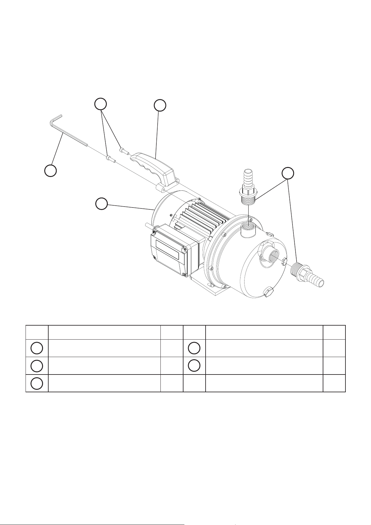
CHECKLIST
D
IMPORTANT: With the pump
removed from its packaging check
for any damage prior to installation.
If any damage is found contact Stuart
Turner Ltd within 24 hours of receipt.
C
Fig. 1
Item
A
E
A
Description Qty
Pump 1 Handle screws 2
Item
D
Description Qty
B
19 mm x G 1 Hose union 2 5 mm Allen key 1
B
Handle 1
C
Your product may vary slightly from the picture above.
E
- 3 -

1 READ BEFORE COMMENCING PUMP INSTALLATION
A. Water storage capacity.
1.11 The cold water storage capacity must be sufficient to meet the flow rates
required by the pumped equipment and any other water using fittings and
appliances, which may be operated simultaneously.
1.12 Ensure the pump is primed as described in the priming section before starting,
damage to the shaft seal will result otherwise. See Section 4 - Commissioning.
B. Water temperature
The water entering the pump must be controlled as follows:
o
o
C.
C.
you must consult the
o
bends.
1.13 The maximum allowable water temperature is 35
1.14 The minimum allowable water temperature is 4
1.15 DO NOT fit a pump if the hot water is heated via a method whereby the water
temperature cannot be controlled, such as solar or solid fuel
pump assist team at Stuart Turner Ltd.
C. Pipework - General
1.16 Secure pipework: Ensure pipework to and from pump is independently
supported & clipped to prevent forces being transferred to inlet and outlet
branches of pump.
1.17 Flux: Solder joints must be completed and flux residues removed prior to pump
installation (flux damage will void any warranty).
1.18 Pipework design: Care should be taken in the design of pipework runs to
minimize the risk of air locks e.g. use drawn bends rather than 90
1.19 DO NOT introduce solder flux to flexible hoses, pumps or pump parts
manufactured from plastic.
1.20 DO NOT allow contact with oil or cellulose based paints, paint thinners or
strippers, acid based descalents or aggressive cleaning agents.
1.21 DO NOT install a non-return valve, or devices which contain non-return
valves, in the suction (inlet) pipework to the pump. The pump must be free
to vent to the supply tank at all times. Exceptions can be made in the
case of suction lift installations when a footvalve is required.
o
1.22 DO NOT bend the flexible hoses beyond 30
. They must be installed as
straight as possible.
1.23 DO NOT connect this pump to the mains water supply.
D. Plumbing & Electrical Installation Regulations
1.24 The plumbing installation must comply with “The Water Supply (Water Fittings)
Regulations 1999” and “BS 6700” building regulations.
1.25 The plumbing installation must be installed by a qualified person.
1.26 The electrical installation must be carried out in accordance with the current
national electrical regulations.
1.27 The electrical installation must be installed by a qualified person.
- 4 -
Cont ...

2 LOCATION - GENERAL
2.11 Access: For emergencies and maintenance the pump must be
easily accessible.
2.12 Protection: The pump must be located in a dry position, frost free and
protected from freezing, particularly when installed in a loft (not
recommended).
2.13 Ventilation: Ensure an adequate air flow to cool the pump. Separate
the pump from other appliances that generate heat. An 80 mm (3 “) air
gap must be maintained around the pump.
2.14 Safety: The motor casing can become very hot under normal
operating conditions. Care must be taken to ensure it cannot be
touched during operation.
2.15 Water retention: Site in a location where in the unlikely event of
a water leak, any spillage is contained or routed to avoid electrics
or areas sensitive to water damage.
2.16 Static inlet pressure: Before deciding where to locate the pump check to ensure
the static inlet head (Fig. 2) meets the minimum requirement of 1 metre and does
not exceed the maximum requirement of 5 metres.
2.17 Ambient temperature: The pump must be sited in a location where the maximum
ambient temperature does not exceed 40
2.18 Pipework: For optimum performance pipework 28 mm should be used. 22 mm is
acceptable, however, any pipe size reduction will reduce the pumps performance.
2.19 Do not run against a closed valve for periods longer than 5 minutes.
2.20 Portable: The pump is suitable for use as a portable unit and is provided with a
carrying handle for this purpose.
2.21 Pipe size: To prevent loss of pressure through pipework, use pipe size to match
pump (19 mm internal diameter) whenever possible, minimising 90° bends
(sweeping bends).
2.22 Isolating valves: If permanently installed, isolating valves should be fitted in
suction and delivery pipework to enable easy isolation and access to the pump.
2.23 Inline strainer: When pump is to be installed in areas where there is risk of
debris or scale build up within the system, you MUST ensure the inlet pipework is
fitted with an inline strainer.
2.24 Suction lift: This pump is capable of a maximum suction lift of 5 m in this case
only, an NRV in the footvalve is permissible (Fig. 3).
o
C.
- 5 -
Cont ...
 Loading...