

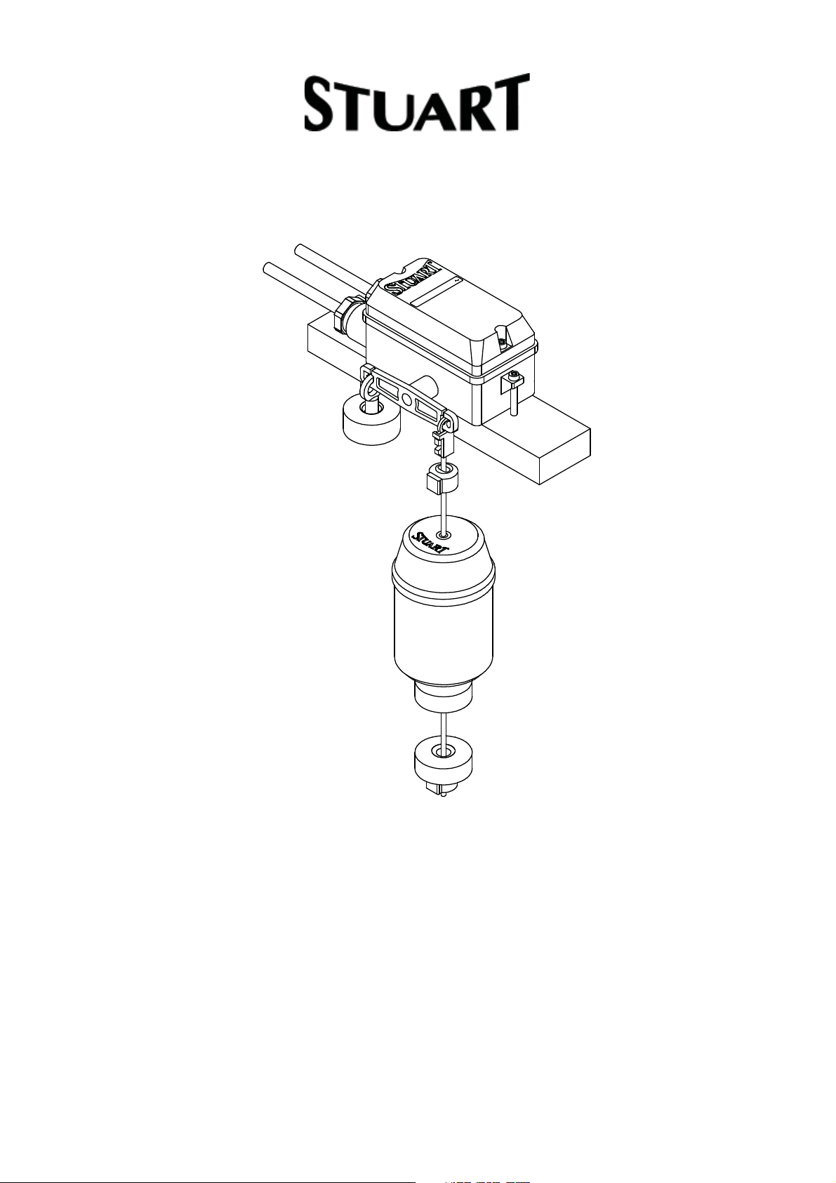
FLOAT SWITCH
OPERATING INSTRUCTIONS
Please leave this instruction booklet with the pump as it
contains maintenance and safety information
(Original Instructions)

MODELS F1 20/8
INDEX . . . . . . . . . . . . . . . . . . . . . . . . . . . . . . . . . . . . . . . . . . . . . . . . Page No
Application . . . . . . . . . . . . . . . . . . . . . . . . . . . . . . . . . . . . . . . . . . . . . . . . . . . . . . . . . . . . . . . . 2
Product Description . . . . . . . . . . . . . . . . . . . . . . . . . . . . . . . . . . . . . . . . . . . . . . . . . . . . . . . . . 3
Limits of Application . . . . . . . . . . . . . . . . . . . . . . . . . . . . . . . . . . . . . . . . . . . . . . . . . . . . . . . . . 3
Technical Specifi cations . . . . . . . . . . . . . . . . . . . . . . . . . . . . . . . . . . . . . . . . . . . . . . . . . . . . . 3
Typical Switch Installations . . . . . . . . . . . . . . . . . . . . . . . . . . . . . . . . . . . . . . . . . . . . . . . . . . . 4
Pre-Assembly of Weights . . . . . . . . . . . . . . . . . . . . . . . . . . . . . . . . . . . . . . . . . . . . . . . . . . . . 6
Siting of the Switch & Installation . . . . . . . . . . . . . . . . . . . . . . . . . . . . . . . . . . . . . . . . . . . . . . 7
Electrical Installation . . . . . . . . . . . . . . . . . . . . . . . . . . . . . . . . . . . . . . . . . . . . . . . . . . . . . . . . 9
Maintenance . . . . . . . . . . . . . . . . . . . . . . . . . . . . . . . . . . . . . . . . . . . . . . . . . . . . . . . . . . . . . . 12
Storage . . . . . . . . . . . . . . . . . . . . . . . . . . . . . . . . . . . . . . . . . . . . . . . . . . . . . . . . . . . . . . . . . . 12
IMPORTANT NOTES
Please read these instructions fully before starting the
installation:
The installation must comply with the relevant water supply,
electrical and building regulations and be installed by a
competent person.
If in doubt, consult Stuart Turner Ltd.
APPLICATION
Stuart float switches are suitable for operation in most water based liquids and provide
automatic control of electrically driven pumps of all types. They can be used for direct
switching of small single phase motors with built in thermal overload protection. They can
also be used to switch larger motors via a contact starter.
WARNING AGAINST MISUSE
This switch must not be used for any other application without the
written consent of Stuart Turner Limited.
This appliance is not intended for use by persons (including children)
with reduced physical, sensory or mental capabilities, or lack of
experience and knowledge, unless they have been given supervision
or instruction concerning use of the appliance by a person responsible
for their safety.
Children should be supervised to ensure that they do not play with the
appliance.
- 2 -
Cont ...

PRODUCT DESCRIPTION
The switch consists of a polypropylene casing, brass counterbalance weights, nylon float
cord and polystyrene float.
The electrical contact is made using mechanical micro switches which are suitable for
operation on voltages up to 250V AC. The switch operation is achieved by the rocking
motion of the arm caused by the rise and fall of the float.
LIMITS OF APPLICATION
Maximum liquid temperature 50oC
Minimum liquid temperature 4
Maximum ambient air temperature 50
o
C
o
C
TECHNICAL SPECIFICATIONS
Gross
Model
F1 20/8 250V a.c. 20 amp 8 amp
Max
Voltage
Current Rating Type
Resistive Inductive H W L Dia L
Single
Pole
Enc.
Rating
IP22 59 56 132 63 125 0.6
Dims (Switch) Dims (Float)
Weight
(packed)
kg
Stuart Turner reserve the right to amend the specification in line with its policy of
continuous development of its products.
- 3 -
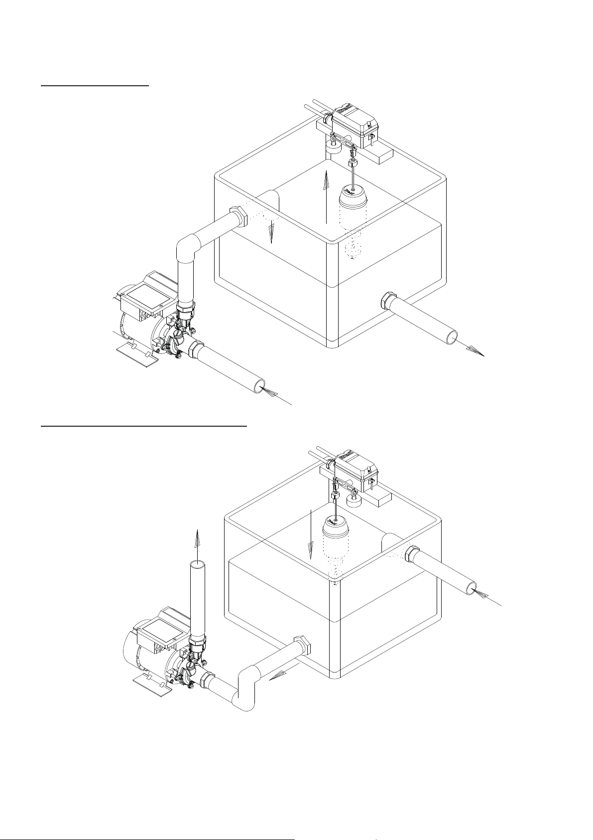
TYPICAL SWITCH INSTALLATIONS
High level cut out (tank filling)
Low level cut out (tank emptying)
Fig. 1
Fig. 2
NOTE : Different positions of float and counter balance, relevant to the operation the
switch is required to carry out.
- 4 -
Cont ...
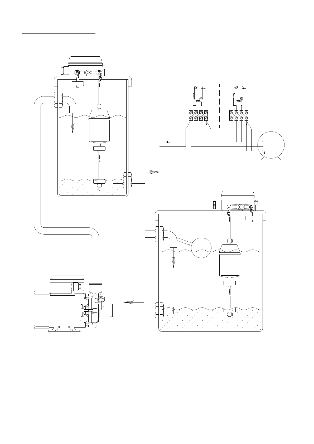
Two switch installation (providing low level cut out protection)
FLOAT SWIT CH 2
FLOAT SWITC H 1
FUSE
L
N
E
SUPPLY 220/240-1PH-AC
WATER SUPPLY
OUTLET
NOTE:D.O.L. SWITCHING RECOMMENDED
FOR MOTORS UP TO 370 WATT THAT ARE
PROTECTED BY AN INTEGRAL THERMAL TRIP
N1
N1 L2 L1N2
L2 L1N2
FLOAT SWIT CH 1
Fig. 3
FLOAT SWITC H 2
MOTOR
WATER SUPPLY
INLET
Fig. 4
For installations where an erratic water supply can be a problem, two switches can be
used as illustrated. Float switch 2 is controlling the start and stopping of the pump, whilst
float switch 1 is providing low level protection by preventing the operation of the pump in
the case of water shortage.
- 5 -
Cont ...

PRE-ASSEMBLY OF WEIGHTS
The switch assembly includes three weights, the position of which relative to the switch
assembly is important for correct functionality of the switch.
a) Counterbalance weight
This is the heaviest of the three (approx
112 g) and is pre-fitted at the factory as
shown in Fig. 6.
If ever there is a need to remove or replace
this weight, it must be re-fitted with the
chamfer upwards as shown in Fig. 7.
Counterbalance
weight
(112 g)
Chamfer
Fig. 6
Fig. 7
b) Float weight and stop weight
These two weights are the same size (approx
90 g), are supplied loose and are
interchangeable.
The float weight must be assembled to the
float with the chamfer upwards as shown in
Fig. 8.
The stop weight must also be assembled
with the chamfer upwards as shown in Fig. 9.
Chamfer
Float
weight
(90 g)
Stop
weight
(90 g)
Fig. 5
Fig. 8
Chamfer
Fig. 9
- 6 -

SITING OF THE SWITCH & INSTALLATION
WARNINGS:
When used on a sump, make sure that it is kept clean. Aggressive
mediums such as concrete dust and cinders may cause damage.
When installing the main float switch casing ensure the mounting
holes (to suit M4 screws) are used. Do not drill the switch casing as
water ingress may subsequently occur which will damage the switch.
Do not allow plastic parts to come into contact with oil or cellulose
based paints, paint thinners or strippers, acid based descalents or
aggressive cleaning agents.
The switch housing must be securely fixed in a horizontal position and should be
protected from being sprayed with water. To permit free action of the switch, a sump
should not be less than 20 cm diameter and at least 45 cm deep. This will permit a
reasonable distance to be obtained between adjustment stops, which in turn will prevent
constant stop / start conditions which could cause damage to motor. See sketch below for
float operating range.
Float Operating Range
70 cm Max
5 cm Min
Fig. 10
Install unit so that the cord, float and the counterbalance weight cannot foul or rub
against anything. The top of the float is marked ‘TOP’. It is important to fit it the right way
up. The float must slide easily up and down the cord . Control the movement of the float
by adjusting the upper and lower level stops. Ensure that when in the lower position the
float and stop weight are clear of the bottom of the sump or tank. The counterbalance
operates the switch when the float lifts up the weighted cord. When the tank is emptied,
the weighted cord plus float must overcome the counterbalance and operate the switch in
the reverse direction. A 0.92 metre nylon cord is provided as standard.
- 7 -

To set switch for sump emptying:
For draining a sump (low level cut out) assemble the float on the left hand side of the
operating lever (as shown in Fig. 11).
Float Switch
Upper level
stop
Counterbalance
weight
Float
weight
Lower level
stop
Float
Cord
Stop weight
Fig. 11
To set switch for sump filling:
Assemble the float on the right hand side of the operating lever (as shown in Fig. 12).
The pump will switch off when the tank is full.
Float Switch
Upper level
stop
Counterbalance
weight
Stop weight
Fig. 11
Float
Float
weight
Cord
Lower level
stop
Cont ...
- 8 -

To change function of switch:
To change the function of the switch from sump emptying to sump filling or vice versa,
proceed as follows:-
Switch lever
Counterbalance
weight support clip
Float cord
support clip
Fig. 13
The counterbalance weight and float assembly must be interchanged. This is done by
manoeuvring both component support clips to the position where easy exit is provided on
the switch lever. Re-assembly is the reversal of this procedure.
ELECTRICAL INSTALLATION
WARNINGS:
The electrical installation must be carried out in accordance with the
current national electrical regulations and installed by a competent
person.
Before starting work on the electrical installation ensure the power
supply is isolated.
The switch and wiring must not be exposed to liquid.
Do not operate switch without terminal box lid correctly fitted.
The F1 switch is suitable for directly switching small output, single phase AC motors
up to 370 watt (0.5 HP), providing the motors are fitted with integral thermal overload
protection. Motors above 370 watt up to 750 watt (1HP) can also be directly switched,
provided the motors are fitted with some means of overload protection and the motor full
load current does not exceed the switch maximum (see technical specification section).
Larger single phase and three phase motors can be controlled by the switch via a
contact starter. The starter should be fitted with hand reset thermal overload protection
and the switch wired in series with the starter coil circuit (see wiring diagram section).
For installations in the United Kingdom, means for disconnection must be incorporated in
the fixed wiring according to the Wiring Regulations.
- 9 -
Cont ...

Earthing
WARNING: Earthing continuity between the supply cords to and from the
switch must be maintained.
The switch is provided with internal earthing terminals which are suitable for the
connection of the earthing conductors within the flexible supply cords.
Wiring
The switch is provided with a set of terminals which allow the connection of flexible
supply cords.
The supply cords should be of the PCP rubber insulated type (HO5RN-F) which is
suitable for a wet environment. Cable and fuse size must be appropriately selected. For
information on cable fitting consult the wiring diagrams and cable gland & supply cord
fitting instructions.
Ensure the electrical connections are securely made and that the micro switch is
connected in to the live line, not the neutral.
Cable Gland & Supply Cord Fitting Instructions (Single phase supply)
The cable gland assembly Fig. 15 (items 1 & 2) provides the necessary protection
against ingress of solid objects and moisture as well as providing cable retention.
Assembly instructions are as follows: -
1. Ensure selected cable sheath
diameter is within the permitted range
(6.5 to 9.5 mm).
2. Strip and prepare the cable sheath
E
and insulators as shown in Fig. 14.
3. Disassemble cable gland as shown in
Fig. 15 and insert cable into position
ensuring ‘O’-ring (item 1) is placed
over the cable before the clamping
insert (item 2) is tightened.
4. Consolidate the stranded conductor
ends by twisting.
5. Insert the phase, neutral and earthing
conductors into the appropriate terminal
block connections (see wiring diagram)
and secure, ensuring all conductor strands
are clamped.
N
L
8
100
70
8
8
70
Fig. 14
- 10 -
Fig. 15
Cont ...

Wiring Diagrams
WIRING DIAGRAM OF F1 MK4
FLOAT SWITCH D.O.L.
SWITCHING OF SINGLE
PHASE MOTOR
Fig. 16
WIRING DIAGRAM OF F1 MK4 FLOAT
SWITCH C/W STARTER AND SINGLE
PHASE MOTOR
- 11 -
Fig. 17
Cont ...

Wiring Diagrams Cont.
WIRING DIAGRAM OF F1 MK4 FLOAT
SWITCH C/W STARTER AND THREE
PHASE MOTOR
Fig. 18
MAINTENANCE
1. No routine maintenance of the switch unit is required, although dependent upon
conditions, a periodical clean of the float and cord should ensure trouble free
operation.
2. Isolate electricity supply before attempting maintenance.
STORAGE
If this product is not installed immediately on receipt, ensure that it is stored in a cool dry
place.
FOR FURTHER TECHNICAL SUPPORT
Phone the Stuart Turner Pump Assist team on 0844 98 000 97. Our staff are trained to
help and advise you over the phone or arrange for a service engineer to call.
- 12 -
Cont ...

YOUR 1 YEAR GUARANTEE
Stuart Pumps are guaranteed by Stuart Turner Limited to be free from defects in
materials or workmanship for the applicable guarantee period from the date of purchase.
The applicable guarantee period is stated in the installation booklet supplied with the
pump. Within the guarantee period we will repair, free of charge, any defects in the pump
resulting from faults in material or workmanship, repairing, exchanging parts or exchanging
the whole unit as we may reasonably decide.
Not covered by this guarantee: Damage arising from incorrect installation, improper use,
unauthorised repair, normal wear and tear and defects which have a negligible effect on
the value or operation of the pump.
Reasonable evidence must be supplied that the pump has been purchased within the
applicable guarantee period prior to the date of claim (such as proof of purchase or the
pump serial number).
This guarantee is in addition to your statutory rights as a consumer. If you are in any
doubt as to these rights, please contact your local Trading Standards Department or
Citizen’s Advice Bureau.
In the event of a claim please telephone Stuart Turner Limited on 0844 980 0097 or
return your pump and flexible hoses with accessories removed, plugs, pipes etc. If you
have any doubt about removing a pump, please consult a professional.
Proof of purchase should accompany the returned pump to avoid delay in investigation
and dealing with your claim.
- 13 -
Cont ...

NOTES
- 14 -
Cont ...

NOTES
- 15 -
Cont ...

DECLARATION OF CONFORMITY
2006/95/EC
BS EN 60335-1, BS EN 60204-1
1999/519/EC
BS EN 62233
2011/65/EU
IT IS HEREBY CERTIFIED THAT THE STUART FLOAT SWITCH COMPLIES WITH THE
ESSENTIAL REQUIREMENTS OF THE ABOVE E.E.C. DIRECTIVE AND STANDARDS.
RESPONSIBLE PERSON
AND MANUFACTURER STUART TURNER LIMITED
HENLEY-ON-THAMES, OXFORDSHIRE
RG9 2AD ENGLAND.
Signed . . . . . . . . . . . . . . . . . . . . . . . . . . . . . . . . . . . . . . . . .
Stuart Turner are an approved company to BS EN ISO 9001:2000
Business Development Director
Stuart Turner Ltd, Henley-on-Thames, Oxfordshire RG9 2AD ENGLAND
Tel: +44 (0) 1491 572655, Fax: +44 (0) 1491 573704
email: pumps@stuart-turner.co.uk web: www.stuart-turner.co.uk
V.A.T. REG. No. 199 0987 92. Registered in England No. 88368. Registered Offi ce: Market Place, Henley-on-Thames
Issue No. 2612/9-08 Pt. No. 17481
 Loading...