

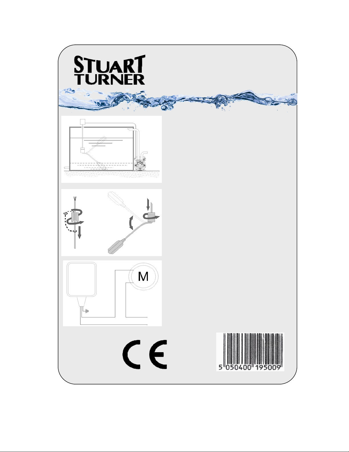
TANK FILLING
FLOAT SWITCH
3M CABLE
Installation:
STOP
START
Fig: 1
1
Fig: 2
To ensure the efficient function of the switch it is
necessary to fix the electric cable inside the tank or
well as illustrated in fig: 1.
The length of the cable section between the Pivot
Point (counterweight) and the float will determine
the length of time the pump runs between starting
and stopping
The switch must be free from obstructions within
the area of the float arc.
No joins should be made to the cable that may
become immersed in water.
Height Counterweight Installation
For correct counterweight installation refer to the
procedure as illustrated in fig: 2.
2
1. Insert the cable into the counterweight, from the
conical shaped end, turning it as shown. This will
result in the detachment of the plastic ring inserted
in the mouth (if required aid detachment by using a
screwdriver) Place the ring at the point of the cable
where the counterweight is to be fixed.
YELLOW /
GREEN
BROWN
BLUE
Fig: 3
Stuart Turner,
Henley-on-Thames,
Oxfordshire,
RG9 2AD
ENGLAND
2. Fix the counterweight on the ring using moderate
pressure and turning it as shown
Electrical Connections
L
N
Connect the float wires as shown in fig: 3
Part No:
19500
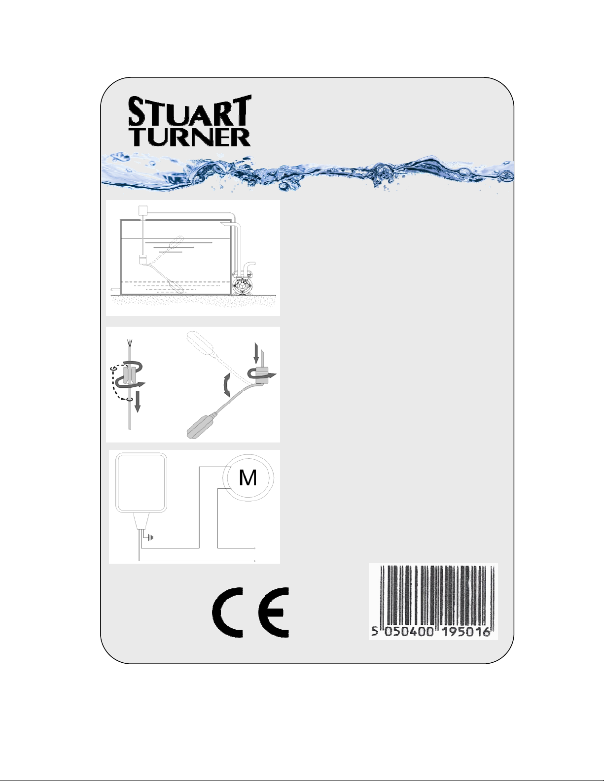
TANK FILLING
FLOAT SWITCH
5M CABLE
Installation:
STOP
START
Fig: 1
1
Fig: 2
To ensure the efficient function of the switch it is
necessary to fix the electric cable inside the tank or
well as illustrated in fig: 1.
The length of the cable section between the Pivot
Point (counterweight) and the float will determine
the length of time the pump runs between starting
and stopping
The switch must be free from obstructions within
the area of the float arc.
No joins should be made to the cable that may
become immersed in water.
Height Counterweight Installation
For correct counterweight installation refer to the
procedure as illustrated in fig: 2.
2
1. Insert the cable into the counterweight, from the
conical shaped end, turning it as shown. This will
result in the detachment of the plastic ring inserted
in the mouth (if required aid detachment by using a
screwdriver) Place the ring at the point of the cable
where the counterweight is to be fixed.
YELLOW /
GREEN
BROWN
BLUE
Fig: 3
Stuart Turner,
Henley-on-Thames,
Oxfordshire,
RG9 2AD
ENGLAND
2. Fix the counterweight on the ring using moderate
pressure and turning it as shown
Electrical Connections
L
N
Connect the float wires as shown in fig: 3
Part No:
19501

Fig: 1
TANK FILLING /
EMPTYING
FLOAT SWITCH
3M CABLE
Installation:
To ensure the efficient function of the switch it is
necessary to fix the electric cable inside the tank or
well as illustrated in fig: 1.
The length of the cable section between the Pivot
Point (counterweight) and the float will determine
the length of time the pump runs between starting
and stopping
The switch must be free from obstructions within
the area of the float arc.
No joins should be made to the cable that may
become immersed in water.
Height Counterweight Installation
For correct counterweight installation refer to the
procedure as illustrated in fig: 2.
1
Fig: 2
Stuart Turner,
Henley-on-Thames,
Oxfordshire,
RG9 2AD
ENGLAND
1. Insert the cable into the counterweight, from the
conical shaped end, turning it as shown. This will
2
result in the detachment of the plastic ring inserted
in the mouth (if required aid detachment by using a
screwdriver) Place the ring at the point of the cable
where the counterweight is to be fixed.
2. Fix the counterweight on the ring using moderate
pressure and turning it as shown
Electrical Connections
See Reverse Of Sheet
Part No:
19638

TANK FILLING /
EMPTYING
FLOAT SWITCH
3M CABLE
START
STOP
STOP
START
Fig: 3
BROWN BLUE
BLUE
BLACK
Fig: 4
Electrical Connections
Emptying (Fig 3 & 4)
To empty a tank or well:
Connect ‘Brown’ and ‘Black’
This will allow the switch to:Open when Down
Close when Up
Rating
= 16(4)A 230V
L
N
Electrical Connections
Filling (Fig 5 & 6)
To fill a tank or well:
Connect ‘Blue’ and ‘Black’
This will allow the switch to:Open when Up
Close when Down
Fig: 5
BROWN
BLACK
Fig: 6
Note: - If used with pumps having a continuous rating of 4 Amps or more
the switch must be connected through a relay or contactor.
- Always ensure the wire that is not used is correctly and fully insulated
L
N

Fig: 1
TANK FILLING /
EMPTYING
FLOAT SWITCH
5M CABLE
Installation:
To ensure the efficient function of the switch it is
necessary to fix the electric cable inside the tank or
well as illustrated in fig: 1.
The length of the cable section between the Pivot
Point (counterweight) and the float will determine
the length of time the pump runs between starting
and stopping
The switch must be free from obstructions within
the area of the float arc.
No joins should be made to the cable that may
become immersed in water.
Height Counterweight Installation
For correct counterweight installation refer to the
procedure as illustrated in fig: 2.
1
Fig: 2
Stuart Turner,
Henley-on-Thames,
Oxfordshire,
RG9 2AD
ENGLAND
1. Insert the cable into the counterweight, from the
conical shaped end, turning it as shown. This will
2
result in the detachment of the plastic ring inserted
in the mouth (if required aid detachment by using a
screwdriver) Place the ring at the point of the cable
where the counterweight is to be fixed.
2. Fix the counterweight on the ring using moderate
pressure and turning it as shown
Electrical Connections
See Reverse Of Sheet
Part No:
19639

TANK FILLING /
EMPTYING
FLOAT SWITCH
5M CABLE
START
STOP
STOP
START
Fig: 3
BROWN BLUE
BLUE
BLACK
Fig: 4
Electrical Connections
Emptying (Fig 3 & 4)
To empty a tank or well:
Connect ‘Brown’ and ‘Black’
This will allow the switch to:Open when Down
Close when Up
L
N
Electrical Connections
Filling (Fig 5 & 6)
To fill a tank or well:
Connect ‘Blue’ and ‘Black’
This will allow the switch to:Open when Up
Close when Down
Fig: 5
BROWN
BLACK
Fig: 6
Rating = 16(4)A 230V
Note: - If used with pumps having a continuous rating of 4 Amps or more
the switch must be connected through a relay or contactor.
- Always ensure the wire that is not used is correctly and fully insulated
L
N
 Loading...