

Stuart Turner 3.2 bar PS User Manual

Installation Instructions For
Monsoon Extra Pressure Sets:
3.2 bar PS
4.7 bar PS
INDEX . . . . . . . . . . . . . . . . . Page No
Application . . . . . . . . . . . . . . . . . . . . . . . . . . 1
Storage . . . . . . . . . . . . . . . . . . . . . . . . . . . . 1
Typical Installation . . . . . . . . . . . . . . . . . . . . 2
Pre-Installatiion Check. . . . . . . . . . . . . . . . . 2
Pump Location. . . . . . . . . . . . . . . . . . . . . . . 2
Sequence of Operation . . . . . . . . . . . . . . . . 4
Pipework Connections . . . . . . . . . . . . . . . . . 4
Pump Connections . . . . . . . . . . . . . . . . . . . 5
INDEX . . . . . . . . . . . . . . . . . Page No
Electrical Installation . . . . . . . . . . . . . . . . . . 8
Commissioning . . . . . . . . . . . . . . . . . . . . . . 12
Maintenance . . . . . . . . . . . . . . . . . . . . . . . . 13
Trouble Shooting Guide . . . . . . . . . . . . . . . . 15
Technical Specifi cation . . . . . . . . . . . . . . . . 17
Noise . . . . . . . . . . . . . . . . . . . . . . . . . . . . . . 17
Environment Protection . . . . . . . . . . . . . . . . 17
PRODUCT DESCRIPTION
Electric motor driven centrifugal pump, complete with pressure vessel and automatic
control system, consisting of flow and pressure switches and electronic controls.
APPLICATION
The Monsoon Extra pressure set range is designed for cold water pressure boosting
applications to hot or cold clean water systems. Inlet pressures to the pump and ambient
temperatures must not exceed the values given in the technical specifications.
This pump set must not be used for any other application without the
written consent of Stuart Turner Limited and in particular, must not be
connected directly to the mains water supply.
This appliance is not intended for use by persons (including children)
with reduced physical, sensory or mental capabilities, or lack of
experience and knowledge, unless they have been given supervision
or instruction concerning use of the appliance by a person responsible
for their safety.
Children should be supervised to ensure that they do not play with the
appliance.
This product should not be used for the supply of water to more than
one dwelling (house, apartment, flat).
STORAGE
If this product is not to be installed immediately on receipt, ensure that it is stored in a
dry, frost and vibration free location in its original packaging.
Please leave this instruction booklet with the pump as it contains
maintenance and safety information
(Original Instructions)
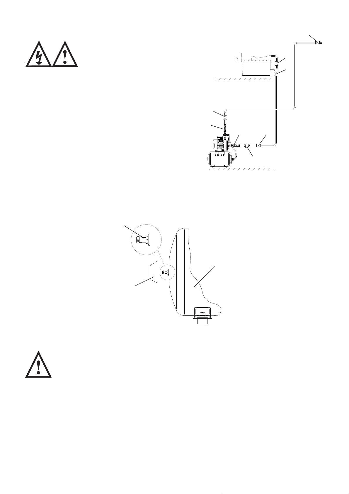
TYPICAL INSTALLATION
1
The plumbing installation must
comply with the following:
1
1
The Water Supply (Water Fittings) Regulations 1999.
BS6700 and building regulations.
Be installed by a competent person.
If in doubt contact Stuart Turner Ltd
1
This diagram should be used for
schematic reference only
1: Isolating valve
2: Inlet strainer
3: Flexible hose
3
3
PUMPS
1
2
Fig. 1
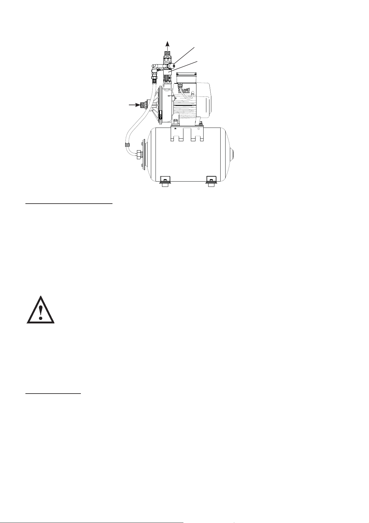
STEP 1 PRE-INSTALLATION CHECK
Your pump set comprises of two major parts, the main pump and pressure vessel. The
pressure vessel is pre-charged with air at the factory to 140 kPa (1.4 bar or 20.3 psi).
This pressure should be checked at the Schrader valve using a tyre pressure gauge and
adjusted if necessary using a car or bicycle pump prior to installation.
Schrader
valve
Plastic
Protector Cap
(unscrew to
access valve)
STEP 2 PUMP LOCATION (GENERAL)
WARNINGS:
The pump must not be located where the inlet pressure to the pump is
greater than permitted.
Care should be taken to protect pump from frost and freezing,
particularly when located in a loft installation.
Pump Location
If possible site the pump in a location where in the unlikely event of a
water leak, any spillage is contained or routed to avoid electrics or
areas sensitive to water damage.
The motor casing can become very hot under normal operating
conditions, care should be taken to ensure it cannot be touched
during operation.
Ensure all components in the down-stream system to be pressurised
are suitably rated to accommodate the final system working pressure.
Pressure
Vessel
Fig. 2
- 2 -
The pump must be installed so that the following conditions are met:
Locate the pump in a frost free horizontal position where it cannot be sprayed with water
and as close to the water source as possible, having a minimum flooded suction head of 1
metre at all times. Ensure the water flow is in the direction of the arrow that is marked on
the flow switch reed clamp (vertically upwards).
The pump is started by a pressure switch and stopped by a flow switch, enabling the unit
to function in both positive or negative head installations.
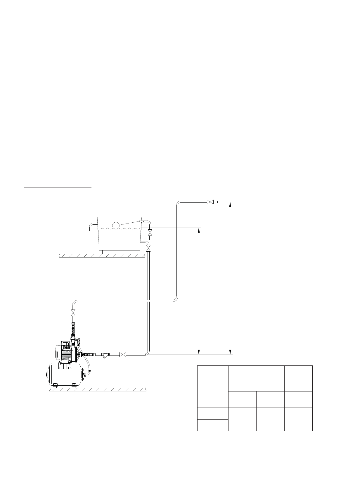
Before deciding where to position the unit, check to ensure the static inlet head of water
above the pump does not exceed 10 metres (Fig. 3). The static outlet head of water above
the pump must not exceed 13 metres (Fig. 3).
The pump must be installed on its anti-vibration mounting feet and must not be screwed
down.
Typical pump locations are in an airing cupboard, or inside a purpose built dry and
ventilated enclosure. The enclosure should have a minimum clearance of 80 mm (3 “)
between the pump and housing on all sides. The enclosure should be secure and access
should only be available by the use of tools.
Typical Installation
To boosted
services
Fig. 3
Diagram showing typical
cold water boosting
installatiion.
Static Inlet Head
PUMPS
Model
3.2
4.7
Static Outlet Head
Static
Inlet
Head
Min.
metres
11013
Max.
metres
Static
Outlet
Head
Max.
metres
- 3 -

STEP 3 SEQUENCE OF OPERATION
The pressure vessel is able to provide for small demands of water, limiting pump starts
to the larger demand requirements. The sequence of operation for the pump set is as
follows:-
1. A terminal fitting in down-stream boosted system is opened, causing water to flow
from fitting.
2. Pressure vessel satisfies initial demand by exhausting it’s pre-charged stored water
capacity.
3. As vessel is exhausted, system pressure falls to pressure switch cut in level.
4. Pump starts and takes over water flow requirements from pressure vessel.
5. Terminal fitting in down-stream boosted system is closed causing flow to stop.
6. Flow switch sensor detects loss of flow activity as flow falls to 1 l/min or less.
7. Pump will stop after the pressure vessel stored water charge is replenished.
8. Pump set is now ready for next demand requirement.
STEP 4 PIPEWORK CONNECTIONS (General)
WARNINGS:
Ensure pipework to and from pump is independently supported to
prevent forces being transferred to inlet and outlet branches of pump.
Do not introduce solder flux to pumps or pump parts manufactured
from plastic. All solder joints should be completed and flux residues
removed prior to pump connection.
Do not allow contact with oil or cellulose based paints, paint thinners
or strippers, acid based descalents or aggressive cleaning agents.
Always install isolating valves to both suction and delivery pipework.
Do not install a non-return valve, or devices
which contain non-return valves, in the
suction (inlet) pipework to the pump. The
pump must be free to vent to the supply
tank at all times.
It must be ensured that the water storage capacity is sufficient to meet the flow rates
required by the pump and any other water using fittings and appliances, which may be
operated simultaneously.
The pipework feeds to the storage tank should be of adequate size to ensure
replenishment rate of tank is sufficient to meet needs of pump.
The pump must be supplied with a dedicated feed direct from the water storage
tank.
To prevent loss of water pressure through pipework use 28 mm suction pipework to the
pump minimising 90° bends.
Isolating valves (not supplied) should be fitted on the suction and delivery pipework to
enable easy isolation and access to the pump.
The 1” inline strainer as supplied should be fitted in the suction line to the pump between
the isolating valve and the pump. This will eliminate the risk of debris or scale entering the
pump.
- 4 -
Outlet
Pressure Switch
Flow Switch
Inlet
Fig. 4
Pipework Connections (Connection between pump and down-stream services to
be boosted)
This should run as far as possible in 22 mm copper tube. Any bend requirements should
be achieved by hand drawing the tube or by use of the appropriate bend fittings. Pipework
should only be reduced to 15 mm copper if necessary when entering any terminal fittings
of this size. By this method the maximum performance of the pump will be maintained. All
pipework should be securely clipped.
STEP 5 PUMP CONNECTIONS (Release And Connection Of Push-in Connectors)
WARNINGS: (Push-in Connectors)
Do not use stainless steel, chrome or nickel plated pipe with Stuart
Turner push-in plumbing connections.
Do not introduce solder flux into the joint or surrounding area as
connectors will be attacked and may fail.
All solder joints should be completed and flux residues removed
before final connection to push-in connections, either on flexible hose
or pump head.
Do not allow contact with oil or cellulose based paints, paint thinners
or strippers, acid based descalents or aggressive cleaning agents.
Hose to Pump
The pump inlet and outlet ports have factory assembled fittings which are specifically
designed for connection to the G ¾ female running nuts on the flexible hoses. The hose
end is fitted with a rubber sealing washer which is held captive within the nut assembly.
Locate the hose into position and screw the nut fully onto the fitting by hand. finally nip
tight with a spanner (4/5 Nm) for a water tight seal (do not overtighten).
- 5 -
Cont ...
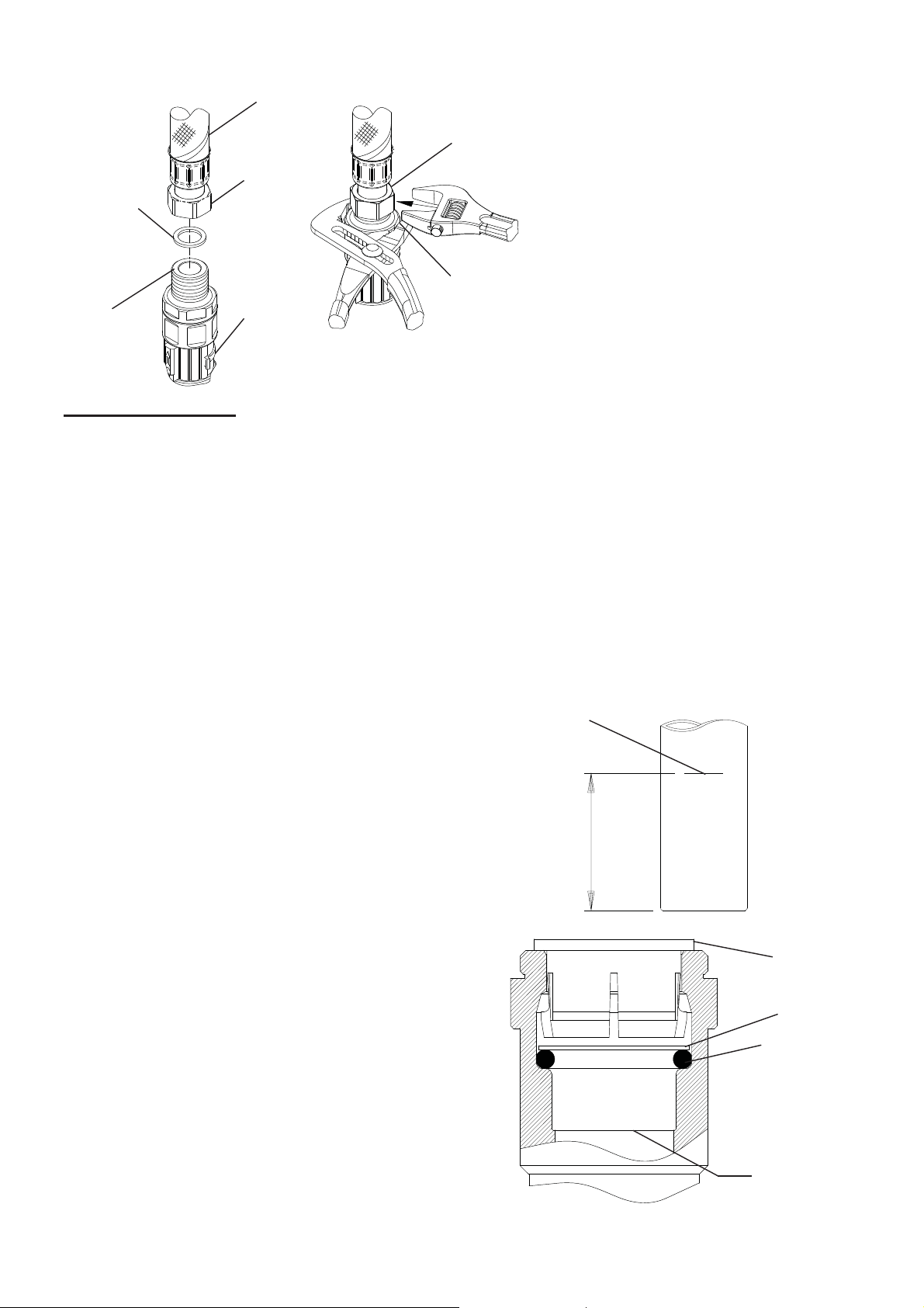
Rubber sealing
washer
Port fitting
Flexible hose
29 mm AF
G ¾ running
nut assembly
Anti-rotation flats
38 mm AF
Reed
switch clamp
assembly
Note: When tightening or loosening the
hose nut assembly, the anti-rotation
flats provided on the inlet and outlet
fittings should be used for placement of
a second spanner as shown. This is to
prevent complete assembly rotation.
It may be necessary to partially rotate
the reed switch clamp assembly on the
outlet fitting to avoid damage during
placement of the second spanner.
Fig. 5
Hose to Pipework
1. Stuart Turner recommend only the use of their 22 mm flexible hoses.
The hoses are fitted with plastic push-in connectors, which must only be connected
with the following:
a) 22 mm diameter copper pipe to BS EN 1057 - R250 (half hard) - Table 3.
b) 22 mm plastic pipe to BS 7291 part 1 and part 2 (Table 1), or part 3 (Table 1) plus
internal support sleeve*.
* The internal bore of the plastic pipe must be supported against collapse with the
pipe manufacturers’ recommended support sleeve (pipe insert).
c) Appropriate plumbing fittings that are compatible and will provide a water tight
connection.
Ensure the pipe is free from all score marks and deformities in the area of the
insertion depth (Fig. 6) and cut the pipe square removing all burrs and sharp
edges to prevent damage to the sealing ‘O’-ring.
2. Prior to inserting pipe into fitting mark the
insertion depth on the wall of the pipe with
a soft pencil at a distance of 35 mm from the
end to be inserted (Fig. 6).
Pencil
mark
22 mm Pipe
3. Check in the mouth of the fitting that
‘O’-ring, nylon washer and collet are
in position.
35 mm
Insert depth
Fig. 6
Collet
Washer
‘O’-Ring
Pipe Stop
Fig. 7
- 6 -
 Loading...