

Merit Water Still
W4000 & W4000/EURO
water still Merit W4000
Instruction Manual
Manuel d’utilisation
Manuale d’istruzioni
Manual de instrucciones
Bedienungsanleitung
700492 / 02 2020
& W4000/EURO
EnglishMerit Water Still W4000
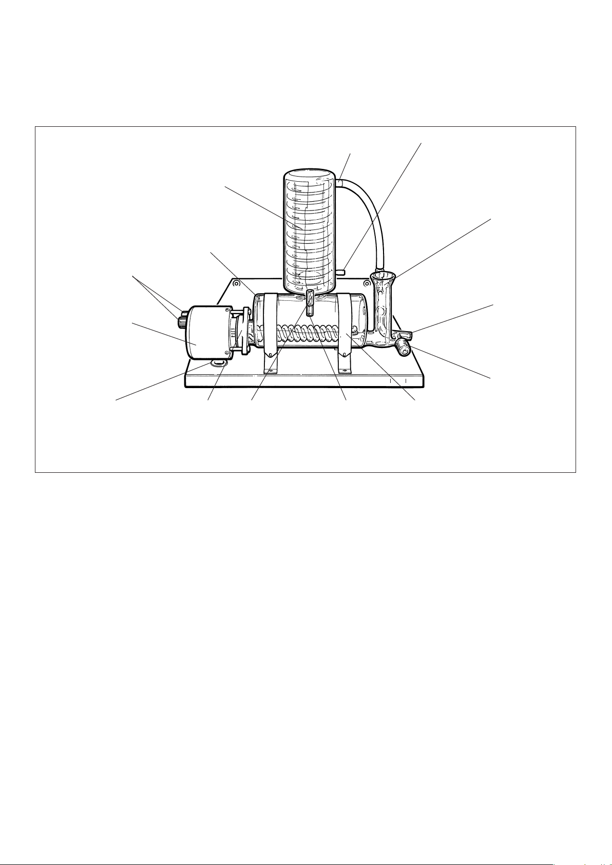
Thermostat reset
buttons
Heater
Grommet
Condenser
Boiler
Gaskets and
flange
Condenser upper outlet
Vent Distillate
outlet
water still Merit W4000
Condenser lower inlet
Constant level
control
Outlet
Stopcock
Straps
Figure 1 General assembly
Before use
If the equipment is not used in the manner described in this
manual the protection provided by the equipment may be
impaired.
Note: The Merit Water Still is classified as “Permanently
Connected Equipment” and should be connected to the electricity
supply by a qualified electrician in the manner described in the
electrical installation section of this manual.
The Merit Water Still is designed to operate under the following
conditions:
❖ For indoor use only
❖ Ambient temperature range +5°C to +40°C
❖ Altitude up to 2000m
❖ Relative humidity not exceeding 80%
❖ Mains supply voltage fluctuations not
greater than ±10% of nominal
❖ Overvoltage category II IEC60364-4-443
❖ Pollution degree 2 IEC664
2
Location
The Merit Water Still can be wall or bench mounted. Select a
convenient location which has access to the following services:–
Electricity Supply
Before connection please ensure that the line supply is suitable.
The Merit Water Still W4000 is suitable for supplies rated at
3kW, 220-240V, 50/60Hz~ single phase.
W4000/Euro is suitable for supplies rated at 3.5kW, 200-240V,
50/60Hz~ single phase. Supplies should be fitted with a 30mA RCD
circuit breaker.
Water Supply
A cold water supply capable of providing a minimum flow rate of 60 l/
hr. Ensure all water supplies are earth bonded.
Drain
A waste water drain located below the level of the still so that the
drain pipe can fall away straight without kinks or bends, to allow an
unimpeded flow. Ensure all drainage systems are earth bonded.
Reservoir
A distillate collection reservoir should be located beneath the still.
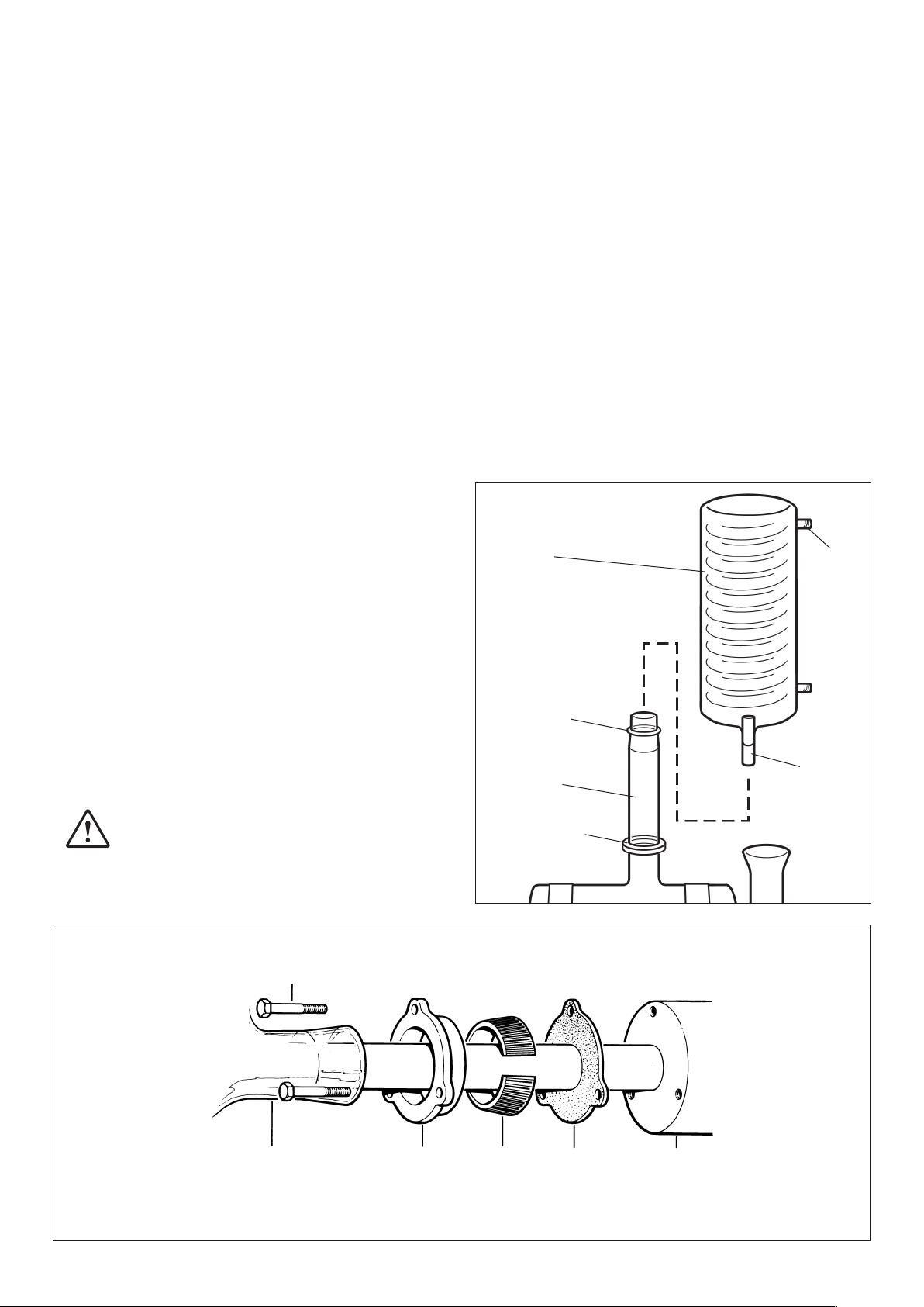
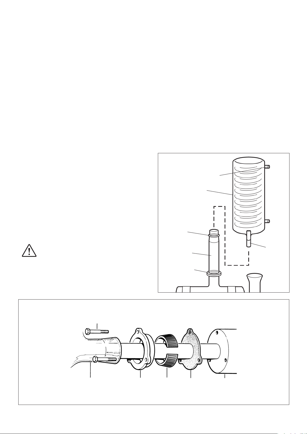
Assembly
i) Insert the 3 bolts provided into the holes in the metal flange
and place the metal flange over the tapered glass tube of the
boiler – ensuring that the flat side of the flange faces the
boiler.
ii) Take the plastic insert and place this round the glass tube
and into the metal flange. Pull the flange and insert towards
the end of the glass tube so that they press onto the glass.
iii) Place the rubber gasket over the heater coils and then insert
the heating element through the tapered glass tube and into
the boiler.
iv) Now secure the heater using the 3 bolts. Do not over tighten.
4. Feed the electric cable of the heater through the hole in the base
of the support stand. Place the boiler and heater assembly in the
‘cradle’ of the stand. Ensure the stopcock on the boiler is facing to
the front. Secure with the 2 straps provided.
5. Ensure that the sealing o-ring and stabilising o-ring are correctly
positioned, as shown in Figure 3. Fit the condenser WC48/M2 by
mounting it onto the vapour tube of the boiler. Ensure the
distillate outlet tube of the condenser faces the front and the
cooling outlet faces parallel to the unit.
Your Merit W4000 has been designed with ease of assembly
specifically in mind, but before commencing assembly please study
the illustrations and text to familiarise yourself with the general
lay¬out. During assembly, follow the sequence of instructions and do
not connect the mains electricity supply until directed.
1. Unpack the water still and identify the following components:–
Qty. Component Catalogue No.
1
Support stand with 2 boiler straps
Boiler
1
Condenser
1
Heater
1
or
Hose Kit
1
Gasket Kit
1
2. Take the metal stand and place in the desired location.
Note that 2 screw holes are provided for wall fitting.
If wall mounting you must ensure you use appropriate
wall fixings that can hold a minimum weight of 28KG. If
you are in any doubt seek professional advice.
3. Take the boiler W4000/B, the heater and gasket kit W4000/GK.
Assemble the heater into the boiler as shown in Figure 2.
W4000/S
W4000/B
WC48 M2
A6/6 (240V)
A6/6/EURO (220V)
W4000/HK
W4000/GK
Figure 3
Condenser
Sealing o-ring
Vapour tube
Stabilising o-ring
Cooling
water
outlet
Outlet
tube
Figure 2 Flange assembly
Bolts
Tapered
glass
tube
Metal
flange
Plastic
insert
Rubber
gasket
Heater
3
6. From the hose kit take the 225mm length of 8mm bore plastics
hose fitted with screwthread connectors at either end. Referring to
Figure 1, screw one end of the hose to the upper outlet of the
condenser and the other end to the glass thread on the constant
level control. If the Still has been correctly assembled the hose
should comfortably reach, without any strain.
7. Take the 1000mm length of 16mm bore plastic hose and carefully
connect to the outlet of the constant level control. For easy
connection first warm the hose with hot water.
Secure with a tie strap.
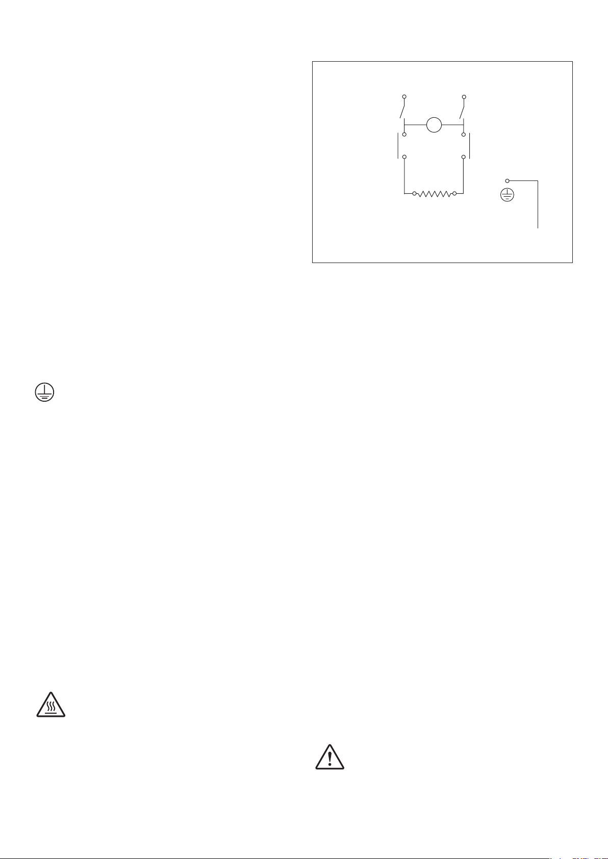
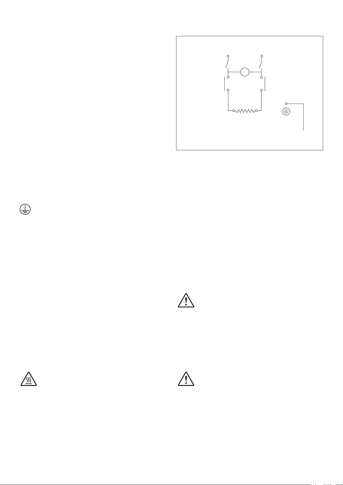
Circuit diagram
L N
(S)
Switch
(W4000/EURO only)
(S)
Thermostat
~240V
Lamp
(S)
Thermostat
8. Lead the free end of the tubing to drain, ensuring it falls away
from the still with no kinks or bends to impede water flow.
9. Ensure the stopcock on the constant level control is closed.
10. Connect the lower inlet of the condenser to the cold water feed
supply. A plastic screwthread connector is provided for easy
attachment to the condenser.
Select good quality tubing and ensure all connections are secured
with hose clips.
11. Connect the distillate outlet on the condenser to a suitable
collection reservoir.
12. Turn on the water supply and test for leaks then turn off the water
supply.
Electrical installation
THIS EQUIPMENT MUST BE EARTHED!
The electrical installation should only be carried out by a qualified
electrician.
The equipment is supplied with 1.7m of flexible triple core circular
cable to CMA 3183 TQ specification. The conductors are 1.5mm2 to BS
6360 Class 5 insulated with E.P.R. The outer sheath is 85°C heat
resisting type C.S.P. to HOFR, BS 6500 Table 9.
Connection to the mains electrical supply, should be via a double pole
30mA RCD isolation circuit breaker with a continuous current carrying
capacity of 15A at 250v and overcurrent protection of 15A, 250V .
These devices should be sited near to the equipment and clearly
marked – “Disconnect device for Merit Water Still“
Connect to the line supply noting that the wires in the instrument lead
are coloured in accordance with the following code:–
Brown – Live
Blue – Neutral
Yellow/Green – Earth
E
Element
Heater flange
(S) Denotes safety critical component.
Operation
1. Turn on the cold water supply and adjust the flowrate to approx.
60 l/h.
Note: It is strongly recommended to measure the flow rate,
failure to do so can result in possible injury from hot water
exiting from the Still. If a flow meter isn't available a simple
measurement can be performed with a 1L beaker.
timed period of five minutes the beaker should be completely
filled five times.
Observe that the water flows via the condenser and into the boiler.
Wait until the boiler has attained its correct operating level and
make sure that the excess water is flowing freely to drain.
2. Switch on the electricity supply to the heating element at the
mains isolation switch.
For the W4000/EURO version, switch on the switch situated on the
heater.
3. After a few minutes the water will start to boil and distillate will
emerge from the condenser. With new glassware, or after cleaning,
it is advisable to allow this to run to drain for approximately 30
minutes before beginning collection.
4. To turn off the still, first turn off the heating element but allow the
cooling water to continue for a further 10 minutes to allow the still
to cool.
Over a
Mains Cable Replacement
If the mains cable requires replacement, only specially prepared spare
mains lead obtained from Cole-Parmer should be used.
Hot warning
Some parts of the product may become hot during
use. These are clearly marked with 'Hot Warning
Labels. Avoid touching these parts.
4
WARNING!
Do not use this equipment to distil any liquid other than
water.
Safety cut-outs
The Merit Water Still is protected by two safety cut-outs:
Boiler heater thermostats
Should the boiler water level fall and expose the
element the thermostats will operate and turn off the
electricity supply to the element.

After operation of either of the thermostats, normal operation may be
resumed by resetting the thermostats by means of their respective
reset buttons mounted on the end of the heater end cover.
Remove the black plastic cover and then press the button – a slight
click will be heard if the thermostat had operated.
Before resetting either thermostat the still should be
allowed to cool completely and the cause of cut-out
operation identified and rectified.
If the thermostats continue to operate consult a qualified electrician or
the Service Department of Cole-Parmer.
Care and maintenance
Note: Before commencing any maintenance, cleaning or fault
finding the equipment should be isolated from the mains electricity
supply. These operations should be only carried out by suitably
qualified personnel.
Only spare parts supplied or approved by Cole-Parmer, or its agent
should be used. Fitting of non-approved parts may affect the
performance or safety of the equipment.
Maintenance
Due to the nature of these parts it is necessary to periodically check
the quality of the plastic connectors and hoses. There should be no
strain on the connectors or hoses. Both the hoses and connectors
should be intact without any cracking. If any damage is discovered on
these parts the Still should immediately be turned off, as detailed
under the "Operation" section of this manual, and not used again
before these parts are replaced. Please refer to the "List of spare parts"
section of this manual for order codes.
5. Into the open funnel of the constant level control carefully add
about 1 litre of 10% formic acid solution or kettle descaler.
Do not use strong acids such as hydrochloric, this can cause severe
corrosion of the metal heating element.
WARNING!
ALWAYS HANDLE ACIDS WITH GREAT CARE. PROTECTIVE
CLOTHING, GLOVES AND FACE-MASKS SHOULD BE WORN
DURING THE DESCALING OPERATION.
REMOVE ANY ACID SPILLS IMMEDIATELY.
Turn on the water supply and fill the boiler to the normal
operating level. The water will flush the acid into the boiler. The
water supply should be turned off when the level in the boiler is
slightly below the overflow.
6. Leave the acid in the boiler to desolve the scale. This may take
some time depending on the severity of the build-up.
7. Open the stopcock and allow the boiler to drain.
Note: If the acid in the boiler has not been completely
neutralised
necessary safety precautions should be observed around the
drain and any effluent control procedures followed.
8. Close the stopcock, turn on the water and allow the boiler to fill
with cold water. Turn off the water, re-open the stopcock and allow
the boiler to drain. Repeat this procedure three times.
9. The Merit Water Still may now be restarted by referring to the
instructions given under “Operation” in this manual.
Note: The stand and outer surfaces of the glassware should be
cleaned using a damp cloth and a mild detergent solution.
the liquid flowing to drain may be highly acidic. All
List of spare parts
Cleaning
Over a period of operation scale deposits will build up inside the
boiler. To obtain optimum performance from the still, the scale should
be removed on a regular basis.
The time span between cleaning depends greatly on the hardness of
the water supply and the amount of use. Frequently used stills in hard
water areas may need descaling once a week whereas in a soft water
area several weeks may elapse before descaling is necessary.
Note: Heavy scaling will reduce distilled water quality and can
shorten the life of the heating element.
It is possible to descale the Merit Water Still without dismantling the
glassware by following these instructions in conjunction with Control
of Substances Hazardous to Health regulations (COSHH) 1988.
1. Switch off the electricity supply to the still and allow it to cool
completely.
2. Turn off the cooling water supply.
3. Open the stopcock on the constant level control and allow the
boiler to drain completely, Close stopcock.
4. Turn on the cooling water supply and allow the boiler to fill to
approximately half way to its normal operating level. Turn off
the water supply.
The following components are available from most laboratory
suppliers. In case of difficulty, please contact Cole-Parmer.
Cat. No.
Boiler
Condenser
Heater (complete with thermostats) 240V
(complete with thermostats) 220V
Set of heater fixings (flange, gasket, insert and bolts)
Hose kit
W4000/B
WC48/M2
A6/6
A6/6/EURO
W4000/GK
W4000/HK
Warranty
Cole-Parmer Ltd. warrants this instrument to be free from defects in
material and workmanship, when used under normal laboratory
conditions, for a period of three (3) years. In the event of a justified
claim Cole-Parmer will replace any defective component or replace
the unit free of charge.
This warranty does NOT apply if damage is caused by fire, accident,
misuse, neglect, incorrect adjustment or repair, damage caused by
incorrect installation, adaptation, modification, fitting of non
approved parts or repair by unauthorised personnel.
This Warranty does not include the heater element which is only
guaranteed for 1 year.
5

Fault finding
In the event of operating difficulties with your Merit Still, please consult the following notes. If
these fail to identify and remedy the fault, then you are advised to seek the help of your
supplier or the Service Department of Cole-Parmer.
Note – Fault finding should only be carried out by suitably qualified people.
Symptom Cause Remedy
1. Water level in boiler is too
LOW. e.g. – heater exposed.
2. Water level in boiler is too
HIGH. e.g. – boiling water
surging into condenser.
3. Water in boiler is “pumped”
out of boiler to drain.
4. Distillate temperature is Flow of cooling water is insufficient.
high, e.g. – above 50°C.
a) Supply of feed/cooling water is
insufficient.
b) Stopcock on boiler inadvertently
left open.
a) Supply of feed/cooling water
is excessive.
b) Flow of drainage water
is constricted.
a) Tubing from condenser distillate
outlet to reservoir is constricted.
b) Vent on condenser distillate
outlet is blocked.
c) Supply of feed/cooling water
is insufficient.
a) Increase flowrate of water to
approx. 60 litres/hour.
b) Close stopcock.
a) Reduce flowrate of water to
approx. 60 litres/hour.
b) Ensure drainage tubing falls
freely.
a) Ensure tubing falls freely to
reservoir without kinks or bends.
b) Remove obstruction.
c) Increase flowrate of water to
approx. 60 litres/hour.
Increase flowrate of water to
approx. 60 litres/hour.
5. Distillate rate less than 4 litres/hour. Mains voltage low Excessive
cooling water flow.
6. Distillate quality poor*. Boiler heavily scaled. Clean boiler.
7. Heater not working. a) Burnt-out heater.
b) Mains electricity fuse blown.
c) Thermostat operated.
8. Persistent tripping of the RCD The integrity of the heater Replace the RCD
* Distillate quality when determined by pH or electrical conductivity is greatly affected by temperature and the presence of absorbed carbon
dioxide.
–
Reduce to 60 litres/hour.
a) Replace heater.
b) Replace fuse.
c) Reset.
6

W4000 & W4000/EURO
Réfrigérant
Bouilleur
Boutons de
rearmement
thermostat
Elément
Chauffant
FrançaisDistillateur
Entrée inférieure de condenseurSortie supérieure de condenseur
Contrôleur
de niveau
Sortie eau de
refroidissement
Œillet
Figure 1 : Vue d’ensemble
Joint
d’étanchéité et
collier de
fixation
Event Sortie
Avant l’utilisation
Si l’appareil n’est pas utilisé de la manière décrite
ci-après, les sécurités prévues peuvent être défaillantes.
N.B. L’appareil à cau distillée MERIT est classé parmis les
«appareils connectés en permanence» et doit être raccordé par un
électricien qualifié comme décrit dans la section
«installation électrique» de ce manuel.
Le distillateur MERIT est prévu pour fonctionner dans les conditions
suivantes :
❖ Utilisation en intérier uniquement.
❖ Température d’utilisation +5°C à 40°C.
❖ Altitude < 2000m.
❖ Humidité relative < 80%.
❖ Alimentation électrique ne variant pas de ±10%
autour de la valeur nominale.
❖ Survoltage catégorie II IEC60364-4-443.
❖ Degré de pollution 2 IEC664.
distillat
water still Merit W4000
Robinet
Anneau de
fixation
7
Installation
Le distillateur MERIT peut être installé sur une paillasse ou fixé au mur.
Choisir un emplacement à proximité des dispositifs suivants:
Alimentation électrique:
Avant de connecter l’appareil, vérifier que l’alimentation électrique est
correcte. Modèle W4000 pour alimentation électrique 3kW 220V,
50/60Hz monophasé. Modèle W4000 EURO pour alimentation
électrique 3.5kW 220V, 50/60Hz monophasé. Des approvisionnements
devraient être équipés d'a 30mA RCD disjoncteur. Les fournitures
doivent être munis d'un disjoncteur de circuit RCD 30mA.
Alimentation en eau:
Source d’eau froide capable de fournir un débit minimum de 60 l/hr.
Evacuation:
Dispositif d’évacuation ou évier situé en dessous de l’appareil de façon
à ce que le tuyau d’évacuation d’eau ne présente aucun coude.
Réservoir de recette:
Un réservoir de recette du distillat pourra être installé sous l’appareil.
Montage
1. Déballer le distillateur et identifier les
composants suivants:–
Qte Designation Référence
1
Support muni de 2 anneaux
métalliques de fixation
Bouilleur
1 775421
Réfrigérant
1 775361
Elément chauffant 220V
1 775422
1 775426
1
de tuyaux
Jeu
Jeu de colliers de fixation
W4000/S
775424
i) Insérez les 3 boulons fournis dans les orifices de la bride
métallique et placez-la sur le tube en verre conique du
bouilleur en vous assurant que le côté plat de la bride est
orienté vers le bouilleur.
ii) Insérer le collier en graphite à l’intérieur du collier
métallique. Tirer le collier métaliique et son insert en
graphite vers l’extrémité du bouiller de façon à ce qui’ils
exercent une pression sur le tube évasé.
iii) Insérer le joint en caoutchouc par dessus les spires de
l’élément chauffant. Introduire l’élément chauffant dans le
bouilleur.
iv) Fixer l’élément chauffant en vissant les 3 boulons. Ne pas
serrer à bloc.
4. Placer le bouiller et l’élément chauffant sur le support. Le robinet
doit alors faire face à l’utilisateur. Faire passer le câble
d’alimentation à travers l’orifice situé à la base du support. Fixer le
bouilleur avec les 2 anneaux métalliques.
5. Enfiler le réfrigérant sur le tube vapeur du bouilleur. L’orifice de
sortie du distillat doit faire face à l’utilisateur.
Figure 3
Sortie d'eau
de refroidissement
Condenseur
2. Installer le support à l’emplacement choisi. 2 trous permettent
de le visser au mur si nécessaire.
En cas de montage mural, vous devez vous assurer
d'utiliser des fixations murales appropriées pouvant
supporter un poids minimum de 28 kg. Demandez
conseil à un professionnel en cas de doute.
3. Prendre le bouilleur, l’élément chauffant et le jeu de colliers.
Assembler selon la figure 2.
Boulon
Joint torique
d'étanchéité
Tube de vapeur
Joint torique de
stabilisation
Tube de
sortie
Figure 2
8
Tube évasé Collier
métallique
Collier en
graphite
Joint en
caoutchouc
Elément
chauffant
6.7.Dans le jeu de tuyaux, prendre le tube 225mm de long et 8mm
de diamètre équipé de connecteurs à vis à ses 2 extrémités.
Visser une extrémité du tuyau sur le raccord à vis supérieur du
réfrigérant et l’autre extrémité sur le raccord à vis du contrôleur
de niveau (voir figure 1).
Prendre le tuyau de 1000 mm de long et 16 mm de diamètre.
Fixer avec précaution son extrémité en sortie du contrôleur de
niveau. Pour faciliter cette opération, passer prélablement
l’extrémité du tuyau sous l’eau chaude. Fixer avec un collier.
8. Placer l’extrémité libre du tuyau vers l’évacuation, en s’assurant
qu’il ne présente aucun coude pouvant perturber l’écoulement
de l’eau.
9. Vérifier que le robinet du contrôleur de niveau est fermé.
Schema de principe
P N
~240V
(S
)
Interrupteur
(S
)
Thermostat
120°C
Lampe
(
S)
Thermostat
120°C
T
10. Visser le connecteur plastique sur le raccord à vis inférieur du
réfrigérant. Fixer le tuyau d’alimentation en eau froide sur ce
connecteur. Choisir un tuyau de bonne qualite et vérifier que
toutes les connexions sont renforcées par un collier.
11. Relier par un tuyau l’orifice de sortie du distillat au réservoir de
recette.
12. Ouvrez l’alimentation en eau et testez la présence de fuite puis
coupez l’alimentation en eau.
Installation electrique
CET APPAREIL DOIT ETRE RELIE A LA TERRE !
L
’installation électrique doit être effectuée par un électricien qualifié.
L’appareil est livré avec un câble de 1,7m (conforme aux spécifications
CMA 3183 TQ). Les fils conducteurs, de section 1,5mm2 (conformes aux
spécifications BS 6360 classe 5) protégés avec de l’EPR. La résistance à
la température est de 85°C et de type CSP à HOFR, BS 6500, table 9.
La connexion à l'alimentation électrique doit être un pôle double
isolation RCD 30mA disjoncteur avec un courant continu nominal de
15A à 250V et la protection de surintensité de 15A, 250V.
Cet équipement doit se trouver à proximité de l’appareil et être
clairement identifier «protection pour distillateur MERIT».
Raccorder le câble selon les indications suivantes:
Marron - Phase
Bleu - Neutre
Jaune/vert - Terre
Si le câble d’alimentation nécessite un remplacement, un câble
spécial, fournis par Cole-Parmer, doit être utilisé.
Avertissement chaud
Certaines pièces du produit peuvent chauffer à
l’utilisation. Elles sont clairement marquées avec des
étiquettes d’avertissement « Chaud ». Évitez de
toucher ces pièces.
Element
Chauffant
Couvercle
(S
) Composant de sécurité.
Mise en route
1. Ouvrir le robinet d’eau froide et régler le débit à 60 litres/heure
environ. L’eau doit circuler à travers le réfrigérant. Attendre que le
niveau d’eau dans le bouilleur soit stable. Vérifier que l’eau
s’écoule normalement vers l’évacuation.
2. Allumer l’interrupteur de l’élément chauffant.
Observer l’ébullition et vérifier que le distillat s’écoule
normalement vers le réservoir de recette.
ATTENTION !
NE PAS UTILISER CET APPAREIL POUR DISTILLER AUTRE CHOSE
QUE DE L’EAU.
Thermostats de sécurité
Le distillateur MERIT est protégé par deux thermostats de sécurité.
Thermostat de sur-chauffe du bouilleur.
Si le controleur de niveau est défectueux et expose
l’elément chauffant à une sur-chauffe, le thermostat agit
et coupe l’alimentation électrique de la résistance.
Après l’opération d’un des deux thermostats, il suffit de les réarmer
en appuyant simplement sur le bouton adéquoit situé à gauche de
l’élément chauffant.
Retirer le capuchon plastique et appuyer sur le bouton (un léger «
clic » doit se produire).
AVANT LE REARMEMENT, IL FAUT ATTENDRE LE
REFROIDISSEMENT DE L’APPAREIL, ET LA CAUSE DU
DECLENCHEMENT DES THERMOSTATS, IDENTIFIEE ET
RECTIFIEE.
Si le thermostat continue de se déclencher, consulter un électricien
qualifié ou le service technique de Cole-Parmer.
9

Entretien et maintenance
Un entretien régulier prolonge la durée de vie de l’appareil et assure
son bon fonctionnement.
Pour des raisons de sécurité, l’entretien et la maintenance de l’appareil
y compris le nettoyage ou le remplacement de composants doivent
être effectués par des personnes qualifiées.
IMPORTANT:
Débrancher l’appareil avant toute operation d’entretien ou de
maintenance.
Nettoyage
Liste des pièces detachées
Les pièces détachées suivantes sont disponibles auprès de votre
revendeur.
Référence
Bouilleur
Réfrigérant
Elément chauffant complet avec thermostat
Thermostat
Jeu de colliers de fixation de l’élément chauffant
(collier métallique, joint caoutchouç insert graphite et boulons)
7.754.21
7.753.61
7.754.22
7.754.23
7.754.24
Après un certain temps de fonctionnement, du tartre peut se déposer
à l’intérieur du bouilleur. Afin d’assurer le bon fonctionnement de
l’appareil, le tartre devra être éliminé régulièrement.
L
’intervalle de temps entre 2 nettoyages dépend de la dureté de l’eau
d’alimentation. Dans les régions où l’eau est très dure, il peut s’avérer
nécessaire de nettoyer le distillateur toutes les semaines. Dans les
régions où l’eau est plus douce, plusieurs semaines peuvent s’écouler
entre deux opérations de nettoyage.
Le tartre se dissout parfaitement dans une solution d’acide formique
diluée à 10%. Certaines solutions de détartrage à usage domestique
peuvent également être utilisées.
ATTENTION !
Il faut toujours manipuler les acides avec prudence. Des
vêtements de protection, des gants et des masques faciaux
devront être utilisés lors des opérations de nettoyage.
1. Eteindre l’interrupteur de l’élément chauffant, débrancher
l’alimentation électrique et laisser refroidir l’eau dans le bouilleur.
2. Fermer le robinet d’alimentation d’eau.
3. Ouvrir le robinet du contrôleur de niveau pour vidanger le
bouilleur. Fermer le robinet.
4. Par l’entonnoir du contrôleur de niveau, verser environ 1 litre d’une
solution d’acide formique diluée à 10%.
Remplir le bouilleur jusqu’ au niveau de fonctionnement, afin
d’éviter que la solution acide ne se déverse à l’égout par le tuyau
d’évacuation.
Garantie
Cole-Parmer Ltd. garantit cet appareil de tout défaut de fabrication
ou de montage pour une utilisation normale en laboratoire et ce
durant trois (3) ans. En cas de défaillance, Cole-Parmer s’engage à
remplacer gratuitement la pièce défectueuse ou l’appareil si ce
dernier était déclaré irréparable.
Cette garantie ne s’applique pas si les dommages sont dus à un
incendie, un accident, une inondation, une négligence ou une
utilisation inadéquate. La garantie ne s’applique pas non plus si
l’appareil n’a pas été installé correctement, réparé par une personne
non qualifiée ou modifié à l’aide de pièces détachées ne provenant
pas de la société Cole-Parmer.
La garantie n’inclut pas l’élément chauffant qui est, quant à lui,
garanti 1 an.
5. Laisser agir l’acide qui doit dissoudre les dépôts de tartre. Le temps
nécessaire dépend du degré d’entartrage.
6. Ouvrir le robinet afin de vidanger complètement le bouilleur.
ATTENTION !
Si la solution de détartrage n’a pas été complètement
neutralisée, l’eau de vidange peut s’avérer être fortement acide.
Prendre les précautions nécessaires au niveau de l’évacuation.
7. Fermer le robinet et remplir le bouilleur d’eau froide. Vidanger le
bouilleur en ouvrant le robinet. Répéter 2 à 3 fois cette opération
de rinçage.
8. Recommencer à distiller l’eau, une fois le bouilleur rempli.
Le distillat obtenu pendant les dix premières minutes qui suivent
une opération de rinçage ne devra pas être utilisé.
Il est important de nettoyer regulierement l’appareil.
10

Incidents de fonctionnement
En cas d’incidents de fonctionnement, consulter le tableu ci-dessous.
Dans le cas où ces informations ne permettraient pas d’identifier
et de résoudre le problème constaté, consulter votre fournisseur ou
les services techniques de Cole-Parmer.
Nature de l’Incident Cause Solution
1. Le niveau d’eau dans le a) Alimentatation en eau insuffisante
bouilleur est trop bas.
ex: l’élément chauffant n’est
plus immergé.
2. Le niveau d’eau dans le a) Alimentation en eau excessive.
ex: l’eau bouillante monte vers
le réfrigérant.
3. L’eau en ébulliton s’écoule du
bouilleur vers l’évacuation.
4. La température du distillat est
élevée (supérieure à 50°C).
b) Robinet du contrôleur de niveau
ouvert.
b) L’évacuation de l’eau se fair mal.bouilleur est trop haut.
a) L’évacuation du distillat vers le
réservoir se fait mal.
b) L’évent sur le réfrigérant est
obstrué.
c) Alimentation en eau insuffisante.
Débit d’eau de refoidissement.
insuffisant.
a) Augmenter le débit jusqu’ à 60
litres/heure environ.
b) Fermer le robinet.
a) Reduire le débit jusqu’ à 60 litres/
heure environ.
b) Vérifier que le tuyau d’évacuation
ne présente aucun coude.
a) Vérifier que le tube reliant
l’orifice d’évacuation du distillat
au réservoir ne présente aucun
coude.
b) Déboucher l’évent.
c) Augmenter le débit jusqu’ à 60
litres/heure environ.
Augmenter le débit jusqu’ à 60
litres/heure environ.
5. Débit du distillat inférieur à
4 litres/heure.
6. Mauvaise qualité du distillat.* Bouilleur entartré. Nettoyer le bouilleur.
7. L’élément chauffant ne marche pas. a) Elément chauffant défectueux.
Déclenchement persistant du RCD Intégrité du thermoplongeur Remplacez le RCD
* Lorsque la qualité du distillat est contrôlée par des mesures de PH ou de conductivité, les valeurs
mesurées sont dépendantes de la température et de la préssence d’oxyde de carbone en solution.
Alimentation électrique inférieure à
220 volts.
b) Thermostats défectueux.
c) Fusible de la prise.
a) Remplacer l’élement chauffant.
b) Remplacer le thermostat
c) Remplacer le fusible.
11

W4000 e W4000/EURO
ItalianoMerit Water Still
Pulsanti di
azzeramento
del termostato
Riscaldatore
Guarnizione
Condensatore
Caldaia
Guarnizioni
e flangia
Uscita superiore del condensatore
Sfiato Uscita
distillato
water still Merit W4000
Entrata acqua di
raffreddamento
Controllo del livello
costante
Verso lo scarico
Rubinetto di
arresto
Cinghie
Figura 1 Montaggio generale
Prima dell'uso
Qualora il dispositivo non venga utilizzato nel modo descritto nel
presente manuale, la protezione fornita dal dispositivo stesso può
risultarne pregiudicata.
N.B. Il Merit Water Still è classificato come “Apparecchiatura a
collegamento permanente” e deve essere collegata
all’alimentazione elettrica da un elettricista qualificato nel modo
descritto nella sezione di installazione elettrica del presente
manuale.
Il Merit Water Still è stato progettato per funzionare nelle seguenti
condizioni:
❖ Da utilizzarsi esclusivamente in ambienti chiusi
❖ Temperatura ambiente compresa tra +5°C e +40°C
❖ Altitudine fino a 2.000 m
❖ Umidità relativa non superiore all'80%
❖ Fluttuazioni della tensione di alimentazione di rete non superiori a
±10% della potenza nominale
❖ Categoria di sovratensione II CEI60364-4-443
❖ Grado di inquinamento 2 CEI664.
12

Posizione
Il Merit Water Still può essere montato a parete o su banco. Scegliere
una posizione comoda con accesso alle seguenti utenze:-
Alimentazione elettrica
Prima di effettuare il collegamento, assicurarsi dell'idoneità
dell'alimentazione di linea. Il Merit Water Still W4000 è adatto ad
alimentazioni di potenza nominale di 3kW, 220-240V, 50/60Hz~
monofase. W4000/Euro è adatto ad alimentazioni di potenza nominale
di 3.5kW, 200-240V, 50/60Hz~ monofase. Forniture dovrebbero essere
dotati di un interruttore differenziale 30mA circuito disgiuntore.
Alimentazione dell'acqua
Alimentazione dell'acqua fredda in grado di fornire una portata
minima di 60 l/ora.
Scarico
Scarico dell'acqua usata posto sotto il livello dello Still in modo che il
tubo di scarico cada lontano senza attorcigliarsi o piegarsi, in modo da
consentire un flusso uniforme e senza strozzature.
Serbatoio
Sotto lo Still occorre posizionare un serbatoio di raccolta del distillato.
della caldaia, facendo in modo che il lato piatto della
flangia sia rivolto verso la caldaia.
ii) Prendere l'inserto in plastica e collocarlo attorno al tubo in
vetro e nella flangia metallica. Tirare la flangia e l'inserto
verso l'estremità del tubo in vetro in modo che premano sul
vetro.
iii) Collocare la guarnizione in gomma sopra le bobine del
riscaldatore e poi inserire l'elemento riscaldatore attraverso il
tubo in vetro conico e nella caldaia.
iv) A questo punto, fissare il riscaldatore usando i tre bulloni
forniti. Non serrare eccessivamente.
4. Collocare il gruppo caldaia e riscaldatore nel ‘supporto’ del
cavalletto. Assicurarsi che il rubinetto di arresto sulla caldaia sia
rivolto verso la parte anteriore. Alimentare il cavo elettrico del
riscaldatore attraverso il foro posto nella base del cavalletto di
supporto. Fissare con le due cinghie fornite.
5. Assicurarsi che l’O-ring di tenuta e l’O-ring ring di stabilizzazione
siano correttamente posizionati, così come illustrato in Figura 3.
Montare il condensatore WC48/M2 sul tubo del vapore della
caldaia. Assicurarsi che il tubo di uscita del distillato del
Figura 3
Bulloni
Tubo in
vetro
conico
Figura 2 Montaggio della flangia
Flangia
metallica
Inserto
in
plastica
Guarniz-
ione in
gomma
Riscaldatore
Montaggio
1. Disimballare il Water Still ed individuare i seguenti componenti:-
Q.tà Componente N. catalogo
1 W4000/S
Cavalletto di supporto con 2 cinghie per la
1 W4000/B
caldaia Caldaia
1 WC48/M2
Condensatore
1 A6/6 (240V)
Riscaldatore
oppure
1 W4000/HK
Kit tubo flessibile
1
Kit guarnizioni W4000/GK
2. Prendere il cavalletto di supporto e collocarlo nella posizione
desiderata. Notare che vi sono due fori per viti per il montaggio a
parete.
Se procedete con il montaggio al muro, assicuratevi di
usare appropriati fissanti che possono sostenere un peso
minimo di 28 Kg. Se avete qualche dubbio, affidatevi ai
consigli di un esperto.
3. Prendere la caldaia W4000/B, il riscaldatore ed il kit guarnizione
W4000/GK. Montare il riscaldatore nella caldaia come illustrato
nella Figura 2.
i) Inserire i 3 bulloni forniti nei fori nella flangia di metallo e
posizionare la flangia di metallo sul tubo di vetro affusolato
A6/6/EURO (220V)
L’uscita dell’acqua di
raffredda-mento
Condensatore
L’O-ring di tenuta
Il tubo del vapore
L’O-ring di
stabilizzazione
condensatore sia rivolto verso le parti anteriore e di
raffreddamento parallele all'unità.
6. Dal kit del flessibile prendere il flessibile in plastica con foro da 8
mm. di 225 mm. di lunghezza montato con i connettori a filetti
alle estremità. Con riferimento alla Figura 1, avvitare un'estremità
del tubo flessibile all'uscita superiore del condensatore e l'altra al
filetto in vetro sul controllo del livello costante. Se lo Still è stato
montato nel modo corretto, il flessibile deve estendersi
agevolmente e senza sollecitazioni.
7. Prendere il tubo flessibile in plastica con foro da 16 mm. di 1000
mm. di lunghezza e collegarlo con cautela all’uscita del controllo
di livello costante. Per un collegamento più agevole, scaldare
prima il tubo flessibile in acqua calda.
Fissare con una fascetta.
8. Portare l’estremità libera della tubatura allo scarico,
assicurandosi che cada lontano dallo Still senza attorcigliarsi o
piegarsi, in modo da consentire un flusso uniforme dell’acqua.
9. Assicurarsi che il rubinetto di arresto sul controllo costante di
livello sia chiuso.
Il tubo di
uscita
13

10. Collegare l'entrata inferiore del condensatore dell'alimentazione
dell'acqua fredda. Per un fissaggio agevole al condensatore, si
fornisce un connettore a filetto in plastica.
Scegliere tubature di buona qualità ed assicurarsi che tutti i
raccordi siano fissati con fascette stringitubo.
Assicurarsi dell'assenza di sollecitazioni sul connettore o sul
flessibile.
11. Collegare l’uscita del distillato sul condensatore ad un serbatoio di
raccolta idoneo.
12. Attivare la condotta di acqua e verificare che non vi siano perdite,
quindi chiudere la condotta dell'acqua.
Installazione elettrica
IL DIPOSITIVO DEVE ESSERE COLLEGATO A TERRA!
L’installazione elettrica deve essere realizzata esclusivamente da un
elettricista
L’apparecchiatura viene fornita con un cavo circolare a triplo nucleo
flessibile da 1,7 m. secondo specifiche CMA 3183 TQ. I conduttori sono
da 1,5 mm2 secondo BS 6360 Classe 5 isolati con E.P.R. IL rivestimento
esterno è resistente ad 85°C tipo C.S.P. secondo HOFR, BS 6500 Tabella
9.
Il collegamento alla rete di alimentazione elettrica, deve essere tramite
un interruttore bipolare 30mA isolamento RCD circuito con una
continua capacità di trasporto di corrente di 15A a 250V e protezione
contro le sovracorrenti di 15A, 250V.
Questi dispositivi devono essere posizionati vicino all’apparecchiatura
e chiaramente contrassegnati - “Dispositivo di scollegamento per Merit
Water Still”
Collegare l’alimentazione di linea notando come i cavi nel connettore
dello strumento siano codificati secondo il colore:-
Sostituzione del cavo di rete
Nel caso in cui occorra sostituire il cavo di rete, occorre usare
esclusivamente cavi di rete di ricambio preparati ad hoc da
Cole-Parmer.
qualificato.
Marrone - Sotto tensione
Blu - Neutro Giallo/
Verde - Terra
Avvertimento caldo
Alcune parti del prodotto possono riscaldarsi durante
l'uso e sono contrassegnate in modo chiaro con
etichette di avviso di elementi caldi. Non toccare queste
parti.
Diagramma del circuito
S N
~240V
(S)
Interruttore
(solo W4000/EURO)
(S)
Termostato
Lampada
(S)
Termostato
Funzionamento
1. Accendere l’alimentazione dell'acqua fredda e regolare il flusso su
circa. 60 l/ora.
Nota: si consiglia vivamente di misurare la portata; la
mancata osservanza di tale norma potrebbe dare luogo a
infortuni causati dall'acqua calda in uscita dallo Still. In caso
di indisponibilità di un flussometro, è possibile realizzare una
semplice misurazione usando un beaker da 1L. Occorre
riempiere il beaker completamente per cinque volte nel giro
di cinque minuti.
Osservare che l’acqua scorra attraverso il condensatore e nella
caldaia. Attendere fino a che la caldaia non abbia raggiunto il
corretto livello di funzionamento ed assicurasi che l’acqua in
eccesso scorra liberamente verso lo scarico.
2. Accendere l’alimentazione elettrica all’elemento riscaldatore con
l'interruttore di isolamento di rete.
Per la versione W4000/EURO, accendere l’interruttore posto sul
riscaldatore.
3. Dopo qualche minuto, l’acqua inizierà a bollire ed il distillato
emergerà dal condensatore. Con recipienti in vetro nuovi, o dopo
la pulizia, si consiglia di lasciarlo scorrere per circa 30 minuti prima
di iniziare la raccolta.
4. Per spegnere lo Still, prima spegnere l’elemento riscaldatore ma
lasciare che l’acqua continui a scorrere per ulteriori 10 minuti in
modo che lo Still si raffreddi.
ATTENZIONE!
Non usare questa apparecchiatura per distillare liquidi che non
siano acqua.
Interruttori di sicurezza
Il Merit Water Still è protetto da due interruttori di sicurezza:
Termostati del riscaldatore della caldaia
Se il livello dell’acqua della caldaia scende e lascia
scoperto l’elemento, entreranno in funzione i
termostati ed interromperanno l’alimentazione
elettrica all’elemento.
Dopo il funzionamento di uno o l’altro dei termostati, è possibile
ripristinare il funzionamento normale azzerando i termostati
mediante i rispettivi pulsanti di azzeramento montati sul coperchio
dell’estremità del riscaldatore.
Togliere il coperchio in plastica nero e poi premere il pulsante: se il
termostato era entrato in funzione, si udrà un leggero scatto.
Prima di azzerare uno o l’altro dei termostati, occorre far
raffreddare completamente lo Still ed individuare ed
eliminare la causa dell’attivazione degli interruttori.
Se i termostati continuano ad entrare in funzione, consultare un
elettricista qualificato o il Servizio di assistenza tecnica di Cole-Parmer.
Cura e manutenzione
Elemento
(S) Denota componente fondamentale di sicurezza.
14
T
Flangia del
riscaldatore
N.B. Prima di iniziare qualsiasi intervento di manutenzione, pulizia o
guasto, occorre isolare l’apparecchiatura dall'alimentazione
elettrica di rete. Solo personale qualificato idoneo deve realizzare
queste operazioni.
Occorre usare esclusivamente parti di ricambio fornite o approvate da
Cole-Parmer o dal suo agente. Il montaggio di parti non approvate
potrebbe impattare sulle prestazioni o sulla sicurezza
dell’apparecchiatura.

Manutenzione
In ragione della natura di queste parti, occorre controllare
periodicamente la qualità dei connettori e dei flessibili in plastica. Essi
non devono presentare alcun segno di sollecitazione. Sia i flessibili che i
connettori devono essere intatti e privi di criccature. Nel caso in cui si
rilevino eventuali danni a queste parti, occorre spegnere
immediatamente lo Still, così come spiegato nella sezione
“Funzionamento” del presente manuale, e non tornare a utilizzarlo se
non dopo aver sostituito queste parti. Per i codici d’ordine, consultare la
sezione “Lista delle parti di ricambio” del presente manuale.
Pulizia
Durante un certo periodo di funzionamento, all’interno della caldaia si
depositeranno accumuli di incrostazioni. Per ottenere le prestazioni
ottimali dallo Still, occorre eliminare regolarmente le incrostazioni.
L’intervallo di tempo tra le pulizie dipende molto dalla durezza
dell’acqua e dall’uso. Le apparecchiature che sono usate
frequentemente e con acqua dura potrebbero necessitare di una pulizia
settimanale, mentre per quelle che usano acqua dolce potrebbe essere
sufficiente una pulizia ogni qualche settimana.
Nota: le incrostazioni pesanti riducono la qualità dell’acqua distillata
e possono diminuire la durata dell’elemento riscaldatore.
È possibile eliminare le incrostazioni dal Merit Water Still senza dover
smontare il recipiente in vetro seguendo queste istruzioni insieme con
le normative sul Controllo delle sostanze pericolose per la salute
(Control of Substances Hazardous to Health- COSHH) 1988.
1. Disinserire l'alimentazione elettrica allo Still e lasciarlo raffreddare
completamente.
7. Aprire il rubinetto di arresto e fare scaricare la caldaia.
Nota: se l’acido nella caldaia non è stato completamente
neutralizzato, il liquido che scorre nello scarico potrebbe essere
altamente acidico. Occorre osservare tutte le
necessarie attorno allo scarico e seguire tutte le procedure di
controllo dell’eventuale effluente.
8. Chiudere il rubinetto di arresto, accendere l’alimentazione
dell’acqua e far riempire la caldaia di acqua fredda. Spegnere
l’alimentazione dell’acqua, aprire nuovamente il rubinetto di arresto
e far scaricare la caldaia. Ripetere questa operazione per tre volte.
9. A questo punto, è possibile riavviare il Merit Water Still secondo le
istruzioni fornite nella sezione “Funzionamento” del presente
manuale. Nota: il cavalletto e le superfici esterne del recipiente in
vetro devono essere puliti usando un panno umido imbevuto in una
soluzione detergente delicata.
precauzioni
Lista di parti di ricambio
I seguenti componenti sono disponibili presso la maggior parte dei
fornitori di materiale da laboratorio. In caso di difficoltà, contattare
Cole-Parmer.
Cat. N.
Caldaia
Condensatore
Riscaldatore (completo di termostati) 240V
(completo di termostati) 220V
Set di accessori di fissaggio per il riscaldatore
(flangia, guarnizione, inserto e bulloni)
Kit tubo flessibile
W4000/B
WC48/M2
A6/6
A6/6/EURO
W4000/GK
W4000/HK
2. Spegnere l'alimentazione dell’acqua di raffreddamento.
3. Aprire il rubinetto di arresto sul controllo di livello costante e far
scaricare completamente la caldaia, poi chiudere il rubinetto di
arresto.
4. Accendere l’alimentazione dell’acqua di raffreddamento e riempire
la caldaia fino a circa la metà del suo livello di funzionamento
normale. Spegnere l’alimentazione dell’acqua.
5. Aggiungere delicatamente 1 litro di 10% soluzione di acido
formico o di anticalcare per pentolini nell’imbuto aperto del
controllo di livello costante. Non usare acidi forti come l’acido
cloridrico, in quanto potrebbe provocare una grave corrosione
dell’elemento di riscaldamento metallico.
ATTENZIONE!
MANEGGIARE SEMPRE GLI ACIDI CON GRANDE ATTENZIONE.
DURANTE LE OPERAZIONI DI ELIMINAZIONE DELLE INCROSTAZIONI,
OCCORRE INDOSSARE ABBIGLIAMENTO PROTETTIVO, GUANTI E
MASCHERINA PER IL VOLTO. ELIMINARE IMMEDIATAMENTE
EVENTUALI PERDITE DI ACIDO.
Accendere l’alimentazione dell’acqua e riempire la caldaia fino al livello
di funzionamento normale. L’acqua farà scorrere l’acido nella caldaia.
Quando il livello nella caldaia è leggermente sotto quello di troppopieno,
occorre spegnere l’alimentazione dell’acqua.
6. Lasciare l’acido nella caldaia in modo che sciolga le incrostazioni.
Questa operazione potrebbe richiedere un tempo variabile a
seconda della quantità di incrostazioni presenti.
Garantie
Cole-Parmer Ltd. garantisce che questo strumento è esente da difetti di
materiali e lavorazione, se usato in normali condizioni di laboratorio, per
un periodo di tre (3) anni. In caso di richiesta giustificata,
Cole-Parmer sostituirà qualsiasi componente difettoso o l’apparecchio
gratuitamente.
La presente garanzia NON si applica in caso di danni causati da incendio,
incidente, uso improprio, negligenza, regolazione o riparazione
incorretta, danni causati da installazione, adattamento, modifica,
installazione di parti non approvate o riparazione realizzate da
personale non autorizzato.
Questa garanzia non comprende l'elemento riscaldante che è
garantita solo per 1 anno.
15

Ricerca guasti
In caso di difficoltà di funzionamento del Merit Still, consultare le seguenti note.
Nel caso in cui queste non riescano ad individuare ed eliminare il guasto, si consiglia di chiedere aiuto al proprio
rivenditore o al Servizio di assistenza tecnica di Cole-Parmer.
Nota - La ricerca guasti deve essere realizzata esclusivamente da persone idoneamente preprarate.
Sintomo Causa Rimedio
1. Il livello dell'acqua nella caldaia è troppo
BASSO, ad es. riscaldatore in vista.
2. Il livello dell’acqua nella caldaia è troppo
ALTO. ad es. acqua bollente
che si solleva nel condensatre.
3. L’acqua nella caldaia viene “pompata”
fuori dalla caldaia per scaricare.
alto, ad es. - sopra i 50°C.
a) Fornire acqua di alimentazione/raffreddamento
è insufficiente.
b) Rubinetto di arresto sulla caldaia
inavvertitamente lasciato aperto.
a) Fornire acqua di alimentazione/raffreddamento
è eccessivo.
b) Il flusso dell’acqua di scarico
si restringe.
a) La tubatura proveniente dall’uscita del distillato
del condensatore al serbatoio è ristretta..
attorcigliarsi o piegarsi.
b) Lo sfiato sull’uscita del distillate del condensatore
è bloccato.
c) Fornire acqua di alimentazione/raffreddamento è
insufficiente.
Il flusso dell’acqua di raffreddamento è insufficiente.
circa 60 litri/ora.
a) Aumentare la portata dell’acqua a
circa 60 litri/ora.
b) Chiudere il rubinetto di arresto.
a) Ridurre la portata dell’acqua a
circa 60 litri/ora.
b) Assicurarsi che la tubatura di scarico cada
liberamente.
a) Assicurarsi che la tubatura cada
liberamente sul serbatoio senza
b) Eliminare l’ostruzione.
c) Aumentare la portata dell’acqua a
circa 60 litri/ora.
Aumentare la portata dell’acqua a4. La temperatura del distillato è
5. Velocità del distillato inferiore a
4 litri/ora.
6. Qualità del distillato scadente*. Caldaia molto incrostata. Pulire la caldaia.
7. Riscaldatore fuori uso. a) Riscaldatore bruciato.
Scatto persistente dell'RCD L'integrità del riscaldatore Sostituire l'RCD
Tensione di rete bassa.
Flusso dell’acqua di raffreddamento eccessivo.
b) Fusibile elettricità di rete bruciato.
c) Termostato azionato.
-
Ridurre a 60 litri/ora.
a) Sostituire il riscaldatore.
b) Sostituire fusibile.
c) Azzerare.
*La qualità del distillato quando è stabilita dal pH o dalla conduttività elettrica è molto influenzata dalla temperatura e dalla presenza di
anidride carbonica assorbita.
16

Alambique de agua Merit
W4000 & W4000/EURO
Espano~l
Botones de reajuste de
temperatura
Calefactor
Salida
Condensador
Caldera
Juntas y
brida
Salida superior del condensador
Respiradero Salida de
destilado
water still Merit W4000
Entrada de agua de
refrigeración
Control de nivel
constante
Para evacuar
Llave de paso
Correas
Figura 1 Montaje general
Antes del uso
Si el equipo no se utiliza de la forma descrita en este manual, se
puede reducir la protección que proporciona el equipo.
N.B. El alambique de agua Merit se clasifica como “Equipo
conectado permanentemente” y debe conectarse a un suministro
eléctrico por un electricista cualificado de la forma descrita en la
sección de instalación eléctrica de este manual.
El alambique de agua Merit está diseñado para utilizarse para las
siguientes condiciones:
❖ Sólo para uso el interior
❖ Intervalo de temperatura ambiente +5°C a +40°C
❖ Altitud hasta 2.000m
❖ Humedad relativa no superior a 80%
❖ Fluctuación de voltaje del suministro eléctrico no superior a
±10% del voltaje nominal
❖ Categoría de sobrevoltaje II IEC60364-4-443
❖ Nivel de contaminación 2 IEC664
17

Colocación
El alambique de agua Merit se puede colocar en la pared o en una
mesa. Seleccione una ubicación adecuada que tenga acceso a los
servicios siguientes:
Suministro eléctrico
Antes de realizar la conexión, asegúrese de que el suministro de red
sea adecuado. El alambique de agua Merit W4000 se puede utilizar con
suministros con un régimen de 3kW, 220-240V, 50/60Hz~ monofásico.
W4000/Euro es adecuado para suministros con un régimen de 3.5kW,
200-240V, 50/60Hz~ monofásico. El producto debe ser cabido con a
30mA RCD disyuntor.
Suministro de agua
El suministro de agua debe ofrecer un caudal mínimo de 60 litros/hora.
Desagüe
El desagüe de aguas residuales debe situarse debajo del nivel del
alambique, de tal forma que el tubo de desagüe caiga sin que tenga
dobleces ni pliegues y permita un caudal sin restricciones.
Depósito
Es necesario situar un depósito de recogida de destilado debajo del
alambique.
Tornillos
ii) Coja la pieza de plástico y colóquela alrededor del tubo de
vidrio y dentro de la brida metálica. Tire de la brida e insértela
hacia el extremo del tubo de vidrio, de tal forma que presione
sobre el vidrio.
iii) Coloque la junta de goma sobre las bobinas del calefactor y
luego inserte el elemento calefactor a través del tubo de
cristal y dentro de la caldera.
iv) Fije el calefactor con los 3 tornillos suministrados. No los
apriete demasiado.
4. Coloque la caldera y la unidad del calefactor en el bastidor del
soporte. Asegúrese de que la llave de paso de la caldera está
orientada hacia la parte delantera. Pase el cable eléctrico del
calefactor por el orificio situado en la base del soporte de apoyo.
Fíjelo con las 2 correas suministradas.
5. Asegúrese de que la junta tórica de sellado y la junta tórica
estabilizadora estén correctamente colocadas, según se muestra
en la Figura 3. Monte el condensador WC48/M2 montándolo en el
tubo de vapor de la caldera. Asegúrese de que tubo de salida de
destilado del condensador está orientado hacia la parte delantera
y que la salida de refrigeración esté paralela a la unidad.
Figura 3
Condensador
La salida de
refrigeración
de aqua
Tubo de
vidrio cónico
Figura 2 Montaje de la brida
Brida
metálica
Pieza
plástico
de
Junta
de
goma
Calefactor
Montaje
1. Desembale el alambique de agua e identifique los siguientes
componentes:
Cant. Componente Nº catálogo
1 W4000/S
Soporte de apoyo con dos correas de
1 W4000/B
caldera Caldera
1 WC48/M2
Condensador
1 A6/6 (240V)
Calefactor
o
1 W4000/HK
Kit de tubos
1
Kit de juntas W4000/GK
2. Coloque el soporte de apoyo en un lugar adecuado. Los dos
orificios roscados están destinados al montaje en pared.
En caso de que lo fije a una pared, debe asegurarse de
que utiliza sujeciones adecuadas que puedan soportar un
peso mínimo de 28 kg. Si tiene cualquier duda, consulte a
un profesional.
3. Coja la caldera W4000/B, el calefactor y el kit de juntas W4000/GK.
Monte el calefactor en la caldera según se muestra en la Figura 2.
i) Inserte los 3 pernos suministrados en los orificios de la brida
metálica y sitúe la brida metálica sobre el tubo cónico de
vidrio de la caldera, asegurándose de que el lado plano de la
brida mire hacia la caldera.
A6/6/EURO (220V)
La junta
tórica de
sellado
El tubo de vapor
La junta tórica
estabilizadora
6. En el kit de tubos, coja el tubo de plástico de 225 mm de longitud
y 8 mm de diámetro que tiene las uniones roscadas en los dos
extremos. Según la Figura 1, rosque un extremo del tubo en la
salida superior del condensador, y el otro extremo en la rosca de
vidrio del control de nivel constante. Si el alambique está montado
correctamente, el tubo debe llegar cómodamente, sin tensiones.
7. Coja el tubo de plástico de 1000 mm de longitud y 16 mm de
diámetro y conéctelo con cuidado a la salida del control de nivel
constante. Para facilitar la conexión, caliente el tubo con agua
caliente.
Fije con una correa de unión.
8. Pase el extremo libre del tubo al desagüe, y asegúrese de que cae
del alambique sin dobleces ni pliegues que dificulten el caudal de
agua.
El tubo
de salida
18

9. Asegúrese de que la llave de paso del control de nivel constante
está cerrada.
10. Conecte la entrada inferior del condensador hasta el suministro de
entrada de agua fría. Se suministra un conector roscado de
plástico para facilitar la conexión al condensador.
Asegúrese de que no haya tensión en el conector o el tubo.
Seleccione tubos de buena calidad y asegúrese de que todas las
conexiones están fijadas con abrazaderas de tubos.
11. Conecte la salida de destilado del condensador a un depósito de
recogida adecuado.
12. Active el suministro de agua y compruebe que no haya fugas; a
continuación, desactive el suministro de agua.0
Instalación eléctrica
EL EQUIPO DEBE CONECTARSE A TIERRA.
La instalación eléctrica sólo debe realizarse por un electricista
capacitado.
El equipo se suministra con un cable circular flexible de triple núcleo
de 1,7 m en conformidad con las especificaciones CMA 3183 TQ. Los
conductores son de 1,5mm2 con aislamiento E.P.R, en conformidad
con las especificaciones BS 6360 Clase 5. La funda exterior es de tipo
C.S.P resistente a una temperatura de 85°C. en conformidad con las
especificaciones HOFR, BS 6500 Tabla 9.
La conexión a la red de alimentación eléctrica, debe ser a través de
un 30mA bipolar aislamiento RCD interruptor de circuito con una
capacidad de corriente continua de 15A a 250V y protección contra la
sobretensión de 15A, 250V.Estos dispositivos deben montarse cerca
del equipo, y deben tener la marca - “Dispositivo de desconexión
para el alambique de agua Merit”
Conecte el equipo al suministro de red y asegúrese de que los hilos
del cable del instrumento están identificados según los siguientes
colores:
Marrón - Corriente
Azul - Neutro
Amarillo/Verde - Toma de tierra
Sustitución del cable de alimentación
Si es necesario sustituir el cable de alimentación, sólo debe utilizarse
el cable de alimentación de recambio especialmente preparado que
suministra Cole-Parmer.
Diagrama de circuitos
C N
~240V
(
S)
Interruptor
(sólo W4000/EURO)
)
(S
ermostato
T
Lámpara
)
(S
ermostato
T
Alcune parti del prodotto possono riscaldarsi durante
l'uso e sono contrassegnate in modo chiaro con
etichette di avviso di elementi caldi. Non toccare queste
parti.
Funcionamiento
1. Abra el suministro de agua fría y ajuste el caudal a unos 60 l/h.
N.B.: Se recomienda encarecidamente medir el caudal; de lo
contrario, el agua caliente que sale del alambique podría producir
lesiones. Si no hay disponible un alambique de agua, se puede
realizar una medida sencilla con un recipiente de 1 litro. El
recipiente se debe llenar completamente cinco veces durante un
período de 5 minutos.
Verifique que el agua circula a través del condensador hasta el interior
de la caldera. Espere hasta que la caldera haya alcanzado su nivel
operativo correcto y asegúrese de que el exceso de agua se vacía
libremente.
2. Encienda el interruptor de corriente para conectar suministro
eléctrico en el elemento calefactor.
Para la versión W4000/EURO, encienda el interruptor situado en el
calefactor.
3. Tras unos minutos, el agua empezará a hervir y el destilado saldrá
del condensador. Con cristalería nueva o después de la limpieza,
se recomienda dejar que purge durante unos 30 minutos antes de
iniciar la recogida.
4. Para desconectar el alambique, primero apague el elemento
calefactor pero deje circular el agua de refrigeración durante
otros 10 minutos para que se enfríe el alambique.
ADVERTENCIA:
No utilice este equipo para destilar otro líquido que no sea agua.
Disyuntores de seguridad
El alambique de agua Merit está protegido mediante dos disyuntores
de seguridad:
Termostatos del calefactor de la caldera
Si el nivel del agua de la caldera disminuye y deja al
descubierto el elemento, se activarán los termostatos y
desconectarán el suministro eléctrico al elemento.
Después de que actúe uno de los termostatos, el funcionamiento
normal se puede reanudar reajustando los termostatos mediante sus
botones de reajuste correspondientes situados en el extremo de la
cubierta del calefactor.
Extraiga la cubierta de plástico negra y luego presione el botón. Se
oirá un ligero 'clic' si se ha accionado el termostato.
Antes de reajustar el termostato, se debe dejar enfriar
por completo el alambique, e identificar y solucionar la
causa del accionamiento del disyuntor.
Si los termostatos siguen actuando, póngase en contacto con un
electricista cualificado o con el Departamento de Servicio Técnico de
Cole-Parmer.
Elemento
(
S) Indica componente crítico de seguridad.
T
Brida del
calefactor
Cuidados y mantenimiento
N.B. Antes de realizar una tarea de mantenimiento, limpieza o
búsqueda de fallos, se debe desconectar el equipo del suministro
eléctrico. Estas operaciones se deben realizar únicamente por
personal debidamente cualificado.
Sólo se deben utilizar piezas de recambio suministradas o autorizadas
por Cole-Parmer o su agente. La instalación de piezas no autorizadas
puede afectar al rendimiento o a la seguridad del equipo.
19

Mantenimiento
Debido a la naturaleza de estas piezas, es necesario comprobar
periódicamente la calidad de los conectores y los tubos de plástico. No
deben existir tensiones en los conectores ni en los tubos, y no deben
presentar grietas. Si se observan daños en estas piezas, se debe
desconectar inmediatamente el alambique, según se indica en la
sección “Funcionamiento” de este manual, y no se debe utilizar hasta
que se sustituyan estas piezas. Consulte la “Lista de piezas de recambio”
en este manual para los códigos de pedido.
Limpieza
Tras un período de funcionamiento, se depositarán incrustaciones en el
interior de la caldera. Para obtener un rendimiento óptimo del
alambique, se deberá eliminar las incrustaciones a intervalos regulares.
7. Abra la llave de paso y deje que se vacíe la caldera.
Nota: Si el ácido de la caldera no se ha neutralizado
completamente, el líquido vaciado puede ser muy ácido. Es
necesario seguir todas las precauciones de seguridad necesarias
en el desagüe, así como todos los procedimientos de control del
efluente.
8. Cierre la llave de paso, abra el agua y deje que se llene la caldera
con agua fría. Apague el agua, vuelva a abrir la llave de paso y deje
que se vacíe la caldera. Repita tres veces este proceso.
9. El alambique de agua Merit puede reiniciarse siguiendo las
instrucciones de la sección “Funcionamiento” de este manual.
Nota: El soporte y las superficies exteriores de la cristalería se
deben limpiar con un paño húmedo y una solución detergente
suave.
El intervalo de tiempo entre la limpieza depende en gran medida de la
dureza del agua y de la cantidad de agua utilizada. Es posible que los
alambiques que se utilicen con frecuencia en áreas de aguas duras
deban desincrustarse una vez a la semana, mientras que, en un área con
aguas blandas, pueden transcurrir varias semanas hasta que sea
necesario realizar una desincrustación.
N.B. Las incrustaciones fuertes reducirán la calidad del agua
destilada disminuirán la vida útil del elemento calefactor.
Es posible desincrustar el alambique de agua Merit sin desmontar la
cristalería. Para ello, siga las siguientes instrucciones en conformidad
con la normativa de Control de sustancias peligrosas para la salud
(COSHH)?1988.
1. Apague el suministro eléctrico del alambique y déjelo enfriar
totalmente.
2. Cierre el suministro de agua de refrigeración.
3. Abra la llave de paso del control de nivel constante y deje que se
vacíe totalmente la caldera. Cierre la llave de paso.
4. Abra el suministro de agua de refrigeración y deje que se llene la
caldera hasta la mitad aproximadamente de su nivel de
funcionamiento normal. Cierre el suministro de agua.
5. En el embudo abierto del control de nivel constante, añada con
cuidado 1 litro de solución de ácido fórmico al 10% o
desincrustador para calderas.
No utilice ácidos fuertes como ácido hidroclórico, ya que pueden
producir una corrosión fuerte en el elemento calefactor de metal.
ADVERTENCIA:
MANIPULE SIEMPRE LOS ÁCIDOS CON CUIDADO EXTREMO. ES
NECESARIO LLEVAR ROPA DE PROTECCIÓN, GUANTES Y
MÁSCARAS DURANTE EL PROCEDIMIENTO DE
DESINCRUSTACIÓN.
LIMPIE INMEDIATAMENTE EL ÁCIDO DERRAMADO.
Abra el suministro de agua y llene la caldera hasta su nivel de
funcionamiento normal. El agua hará pasar el ácido a la caldera. El
suministro de agua se debe cerrar cuando el nivel de la caldera
esté ligeramente por debajo del desbordamiento.
Lista de piezas de recambio
Los siguientes componentes pueden obtenerse de la mayoría de
proveedores de laboratorio. En caso de dificultades de obtención,
póngase en contacto con Cole-Parmer.
Nº cat.
Caldera
Condensador
Calefactor (con termostatos) 240V
(con termostatos) 220V A6/6/EURO
Juego de piezas del calefactor
(brida, junta, pieza y tornillos)
1 Kit de tubos
W4000/B
WC48/M2
A6/6
W4000/GK
W4000/HK
Garantía
Cole-Parmer Ltd. garantiza que este equipo está libre de defectos en los
materiales y la fabricación cuando se utiliza en condiciones normales
de laboratorio durante un período de tres (3) años. En caso de
presentarse una reclamación justificada, Cole-Parmer sustituirá los
componentes defectuosos o la unidad sin cargo alguno.
Esta garantía NO se aplica a los daños producidos por incendios,
accidente, uso incorrecto, negligencia, ajuste o reparación incorrectos,
daños producidos por una instalación incorrecta, adaptación,
modificaciones, montaje de piezas no autorizadas o reparación
realizada por personal no autorizado.
Esta garantía no incluye el elemento calentador que sólo está
garantizado por 1 año.
6. Deje el ácido en la caldera para disolver las incrustaciones. Es
posible que tarde en disolverlas según el grado de incrustación.
20

Localización de fallos
En caso de dificultades de funcionamiento del alambique Merit, consulte las notas siguientes.
Si estas notas no permiten identificar y solucionar el fallo, debe buscar asistencia de
su proveedor o del Departamento de Servicio Técnico de Cole-Parmer.
Nota - La localización de fallos sólo debe realizarse por personal debidamente cualificado.
Síntoma Causa Solución
1. El nivel de agua de la caldera es demasiado
BAJO. ej.: - calefactor expuesto.
2. El nivel de agua de la caldera es demasiado
ALTO. ej.: - agua hirviendo
pasa al condensador.
3. El agua de la caldera se “bombea”
fuera de la caldera y se vacía.
alto, ej.: - superior a 50°C.
5. Caudal del destilado inferior a
4 litros/hora.
6. Calidad del destilado deficiente*: Caldera con muchas incrustaciones. Limpie la caldera.
a) Suministro de agua de entrada/refrigeración
insuficiente.
b) La llave de paso de la caldera
se ha dejado abierta inadvertidamente.
a) Suministro de agua de entrada/refrigeración
excesivo.
b) Caudal de agua de desagüe
restringido.
a) El tubo que va de la salida de destilado
del condensador hasta el depósito está restringido.
b) El respiradero en la salida de destilado
del condensador está bloqueado.
c) Suministro de agua de entrada/refrigeración
insuficiente.
Caudal de agua de refrigeración insuficiente. 4. La temperatura del destilado es
Voltaje de red bajo.
Caudal de agua de refrigeración excesivo.
a) Aumente el caudal de agua a
aprox. 60 litros/hora
b) Cierre la llave de paso.
a) Reduzca el caudal de agua a
aprox. 60 litros/hora
b) Asegúrese de que el tubo de
desagüe cae libremente.
a) Asegúrese de que el tubo cae
libremente al depósito sin dobleces
ni pliegues.
b) Elimine la obstrucción.
c) Aumente el caudal de agua a aprox.
60 litros/hora
Aumente el caudal de agua a
aprox. 60 litros/hora
Reduzca el caudal a 60 litros/hora.
7. El calefactor no funciona. a) Calefactor quemado.
b) Fusible de red eléctrica fundido.
c) Accionamiento del termostato.
Desconexión permanente del interruptor diferencial La integridad del calentador Sustituir el interruptor diferencial
a) Sustituya el calefactor.
b) Sustituya el fusible.
c) Reajuste.
* La calidad del destilado determinada por pH o conductividad eléctrica está muy influida por la temperatura y la presencia de dióxido de
carbono absorbido.
21

asserdestillier-Apparat
W4000 & W4000/Euro
DeutschMerit W
Thermostat
Rückstellknöpfe
Heizung
Tülle
Kondensator
Boiler
Dichtungen
und Flansch
Oberer Auslass des Kondensators
water still Merit W4000
Öffnung Destillataustritt Laschen
Kaltwasserzufuhr
Füllstandsregler
Zum Ablauf
Absperrhahn
Abbildung 1 Allgemeiner Aufbau
Vor dem Gebrauch
Wird das Gerät nicht entsprechend dieser Anleitung betrieben, so
können die Schutzfunktionen des Geräts beeinträchtigt werden.
HINWEIS: Der Merit Wasserdestillier-Apparat gilt als ortsfestes Gerät
und muss von einem Elektrofachmann entsprechend den
Anweisungen im Kapitel „Elektrischer Anschluss“ angeschlossen
werden.
Der Merit Wasserdestillier-Apparat ist für den Einsatz unter folgenden
Bedingungen ausgelegt:
❖ Nur für den Gebrauch in Innenräumen
❖ Umgebungstemperatur zwischen +5°C und +40°C
❖ Höhe: bis zu 2000 m
❖ Relative Feuchte nicht über 80%
❖ Netzspannungsschwankungen nicht über 10%
❖ Überspannungsklasse II IEC60364-4-443
❖ Verschmutzungsgrad 2 IEC664
Einsatzbeschränkungen
Dieses Produkt entspricht den geltenden EU-Normen für
Hochfrequenzstörungen so dass ein störungsfreier Betrieb in
Verbindung mit Geräten ähnlichen Standards vorausgesetzt werden
darf. Wir können jedoch nicht gewährleisten, dass im Umfeld
betriebene Geräte diesen Anforderungen entsprechen, oder dass
keine Störungen in der Praxis auftreten werden. Bei
Verletzungsgefahr, sowie bei Gefahr von Schädigung oder Verlust
durch fehlerhafte Funktionsweise aufgrund von
Hochfrequenzstörungen (aber auch für allgemeine Informationen
bezüglich des Gebrauchs) wenden Sie sich bitte an die
Kundendienstabteilung von Cole-Parmer.
22

Aufstellung
Der Merit Wasserdestillier-Apparat kann an der Wand oder auf einem
Tisch montiert werden. Wählen Sie einen zweckmäßigen Aufstellort
der folgende Anschlüsse bietet:
Stromversorgung
Kontrollieren Sie vor dem Anschließen bitte ob die Stromversorgung
für dieses Gerät geeignet ist. Der Merit Wasserdestillier-Apparat W4000
benötigt folgende Stromversorgung: 3kW, 220-240V,
50/60Hz~ einphasig. Das Modell W4000/Euro benötigt folgende
Stromversorgung 3.5kW, 200-240V, 50/60Hz~ einphasig.
Versorgungsmaterialien sollten mit a gepasst werden 30mA RCD
Stromunterbrecher
Wasserzufuhr
Eine Kaltwasserversorgung mit einem Mindestdurchsatz von 60 l/h.
Abfluss
Ein Abwasserablauf unterhalb des Destillierapparats, sodass der
Abwasserschlauch knickfrei hängen kann ohne den Ablauf zu
beeinträchtigen.
Behälter
Unter dem Destillierapparat muss sich ein Auffangbehälter für das
Destillat befinden.
ii) Nehmen Sie den Kunststoff-Sitzring und setzen Sie ihn so
auf das Glasrohr auf, dass er in den Metallflansch reicht.
Ziehen Sie Flansch und Sitzring zusammen in Richtung
Glasrohrende, sodass beide auf das Glas drücken.
iii) Positionieren Sie die Gummidichtung auf den Heizspiralen
und setzen Sie dann das Heizelement durch das verjüngte
Glasrohr in den Boiler ein.
iv) Jetzt kann die Heizung mit den 3 beiliegenden Schrauben
befestigt werden. Schrauben nicht zu stark anziehen.
4. Setzen Sie Boiler und Heizgerät in das Gestell ein. Dabei muss der
Absperrhahn nach vorne zeigen. Führen Sie das Stromkabel des
Heizgeräts durch die Öffnung unten am Ständer ein. Sichern Sie
das Gerät mit den beiden beiliegenden Laschen.
5. Achten Sie darauf, dass die beiden O-Ringe zur Abdichtung und
Stabilisierung entsprechend Abbildung 3 richtig eingesetzt sind.
Montieren Sie nun den Kondensator WC48/M2, indem Sie ihn am
Kondensschlauch des Boilers befestigen. Achten Sie darauf, dass
der Destillataustrittschlauch des Kondensators nach vorne zeigt
und dass die Kühlaustrittsflächen parallel zum Gerät verlaufen.
Abbildung 3
Schrauben
Verjüngtes
Glasrohr
Abbildung 2 Flanschmontage
Metall-flansch
Gummi-dichtung Kunststoff-
Sitzring
Heizung
Montage
1. Packen Sie den Wasserdestillier-Apparat aus und vergleichen Sie
die Komponenten mit folgender Aufstellung:
Anz. Bauteil Katalog-Nr.
1
Ständer mit 2
1
Boiler
1
Kondensator
1
Heizung
oder
1
Schlauch-Set
1
Dichtungssatz
2. Stellen Sie den Metallständer an einem geeigneten Ort auf.
Beachten Sie die beiden Schraubenlöcher für eine evtl.
Wandmontage.
Verwenden Sie bei einer Wandmontage unbedingt
passende Aufhängeelemente, die mindestens 28kg
tragen können. Sollten irgendwelche Zweifel bestehen,
suchen Sie Rat bei einem Experten.
3. Nehmen Sie den Boiler W4000/B, das Heizelement und den
Dichtungssatz W4000/GK zur Hand. Montieren Sie das Heizgerät
nach Abbildung 2.
i) Die 3 mitgelieferten Schrauben in die Löcher des
Metallflansches einsetzen, und den Metallflansch auf das
konische Glasrohr des Heizkessels setzen. Dabei sicherstellen,
dass die flache Seite des Flansches in Richtung des
Heizkessels zeigt.
Boiler-Laschen
W4000/S
W4000/B
WC48/M2
A6/6 (240V)
A6/6/EURO (220V)
W4000/HK
W4000/GK
Kondensator
O-Ringe zur
Abdichtung
Kondensschlauch
O-Ringe zur
Stabilisierung
6. Nehmen Sie aus dem Schlauch-Set den 8 mm Kunststoffschlauch
(225 mm Länge), der an beiden Ende einen Schraubverbinder
aufweist. Schrauben Sie ein Schlauchende in den oberen
Kondensatoraustritt und das andere Ende in das Glasgewinde am
Füllstandsregler (siehe Abbildung 1). Bei korrekter Montage des
Destillier-Apparats besitzt der Schlauch ausreichende Länge und
muss nicht unter Zug montiert werden.
7. Nehmen Sie den 16 mm Kunststoffschlauch mit 1000 mm Länge
und schließen Sie diesen vorsichtig am Austritt der
Füllstandsregelung an. Der Schlauch lässt sich leichter
aufschieben wenn er zuvor in heißem Wasser erwärmt wurde.
Sichern Sie den Schlauch mit einem Befestigungsband.
8. Führen Sie das freie Schlauchende zum Ablauf. Achten Sie dabei
auf knickfreien Verlauf und unbehinderten Wasserablauf.
9. Stellen Sie sicher, dass der Absperrhahn des Füllstandreglers
geschlossen ist.
Kühlwasser
-auslass
Auslassrohr
23

10. Schließen Sie den unteren Kondensatoreintritt an die
Kaltwasserversorgung an. Der Anschluss an den Kondensator wird
durch einen Kunststoff-Schraubverbinder erleichtert. Achten Sie
darauf, dass Verbindungselement und Schlauch nicht unter Zug
stehen.
Verwenden Sie nur hochwertige Schläuche und sichern Sie alle
Anschlüsse mit Schlauchklemmen.
11. Verbinden Sie den Destillataustritt am Kondensator mit einem
geeigneten Auffangbehälter.
12. Wasserzufuhr öffnen und auf Leckagen prüfen. Anschließend die
Wasserzufuhr wieder schließen.
Elektrischer Anschluss
DIESES GERÄT MUSS GEERDET WERDEN!
Der elektrische Anschluss muss von einem Elektrofachmann
ausgeführt werden.
Das Gerät wird mit einem 3-adrigen Rundkabel von 1,7 m Länge nach
Spezifikation CMA 3183 TQ geliefert. Die Leiter haben einen
Querschnitt von 1,5mm2 nach BS 6360 Klasse 5 und sind mit EthylenPropylen-Kautschuk (EPK) isoliert. Die CSP Außenummantelung hat
eine Wärmebeständigkeit von 85°C nach HOFR, BS 6500 Tabelle 9.
Der Anschluss an die elektrische Stromversorgung, sollte über eine
Doppel-Pole 30mA RCD Isolation Schutzschalter mit einem
kontinuierlichen Strombelastbarkeit von 15A bei 250V und
Überstromschutz von 15A, 250V werden.
Diese Vorrichtungen müssen in Gerätenähe montiert werden und
folgende Aufschrift tragen: „Abschaltvorrichtung für Merit
Wasserdestillier-Apparat“
Schließen Sie das Kabel am Netz an. Die Leiter des Gerätekabels sind
wie folgt farblich gekennzeichnet:
Braun - Phase
Blau - Null
Gelb/Grün - Erde
Netzkabel ersetzen
Wenn das Netzkabel ersetzt werden muss, darf nur ein spezielles
Ersatzkabel von Cole-Parmer verwendet werden.
Schaltplan
P N
~240V
(S)
Schalter
(nur für W4000/EURO)
(S)
Thermostat
Lampe
Element
(S)
Thermostat
E
Heizungsflansch
Einige Teile des Produkts können während des
Gebrauchs heiß werden. Diese Teile sind eindeutig
mit Warnungen gekennzeichnet. Den Kontakt mit
diesen Teilen vermeiden.
Bedienung
1. Drehen Sie die Kaltwasserversorgung auf und stellen Sie die
Durchflussrate auf ca. 60 l/h ein.
Hinweise: Es wird dringend empfohlen die Durchflussrate zu
messen. Andernfalls kann es zu möglichen Verletzungen durch
austretendes Heißwasser aus dem Destillierapparat kommen. Ist
kein Durchflussmessgerät vorhanden, so kann eine einfache
Messung auch mit einem 1 l Behälter vorgenommen werden. Über
einen Zeitraum von fünf Minuten muss sich der Behälter fünf Mal
vollständig füllen.
Beobachten Sie, ob das Wasser durch den Kondensator und in den
Boiler läuft. Warten Sie bis der Boiler den richtigen Füllstand erreicht
hat und sorgen Sie dafür, dass überschüssiges Wasser unbehindert
ablaufen kann.
2. Schalten Sie am Trennschalter die Stromversorgung zum
Heizelement ein.
Bei der Geräteversion W4000/EURO müssen Sie zudem den
Schalter am Heizgerät selbst einschalten.
3.4.Das Wasser beginnt nach ein paar Minuten zu kochen, sodass
Destillat aus dem Kondensator ausläuft. Bei neuen Glasgefäßen
bzw. nach der Reinigung empfiehlt es sich das Gerät etwa 30
Minuten lang laufen zu lassen, bevor eine Destillatentnahme
stattfindet.
Zum Abschalten des Destillierapparats wird zuerst das
Heizelement abgeschaltet. Lassen Sie dann das Kühlwasser
weitere 10 Minuten durchlaufen damit sich das Gerät abkühlen
kann.
ACHTUNG!
Dieses Gerät darf ausschließlich zur Destillation von Wasser
verwendet werden.
Sicherheitsschalter
Der Merit Wasserdestillier-Apparat ist durch zwei Sicherheitsschalter
geschützt:
Boiler-Heizthermostat
Sollte der Füllstand im Boiler fallen, sodass die
Heizelemente freigelegt werden, aktivieren sich die
Thermostate und schalten die Stromzufuhr zum
Heizelement aus.
Nach Aktivierung einer der beiden Thermostate kann der
Normalbetrieb wieder aufgenommen werden, indem der Thermostat
durch den Rückstellknopf auf der Endabdeckung der Heizung wieder
zurückgestellt wird.
Nehmen Sie die schwarze Kunststoffabdeckung ab und drücken Sie
dann den Knopf - Sie hören ein leichtes Klickgeräusch, wenn der
Thermostat tatsächlich aktiviert worden ist.
Vor dem Rückstellen eines Thermostats den
Destillierapparat vollständig abkühlen lassen und die
Ursache der Störung ausfindig machen und beheben.
Bei wiederholtem Auslösen der Thermostate wenden Sie sich bitte an
einen Elektrofachmann oder setzen Sie sich mit der
Kundendienstabteilung von Cole-Parmer in Verbindung.
(S) Bezeichnet sicherheitsrelevantes Bauteil.
24

Pflege und Wartung
HINWEIS: Vor allen Instandhaltungs- und Reinigungsarbeiten, sowie
vor der Fehlersuche das Gerät vom Netz trennen. Diese Arbeiten
müssen von entsprechend geschultem Personal ausgeführt werden.
Es dürfen nur Ersatzteile verwendet werden, die von Cole-Parmer
dessen Niederlassungen geliefert wurden. Der Einbau anderer Teile
kann die Leistung und Sicherheitsfunktionen dieses Geräts
beeinträchtigen.
Wartung
Aufgrund der Beschaffenheit dieser Komponenten müssen
Kunststoffschläuche und Verbindungselemente regelmäßig kontrolliert
werden. Schläuche und Verbindungselemente müssen zugfrei montiert
sein. Beide Komponenten müssen unversehrt sein und dürfen keine
Risse aufweisen. Wird eine Beschädigung festgestellt, so ist der
Destillierapparat sofort abzuschalten (siehe hierzu den Abschnitt
"Bedienung" in dieser Anleitung) und darf erst nach Austausch der
entsprechenden Teile wieder in Betrieb genommen werden.
Bestellnummern finden Sie im Abschnitt "Ersatzteilliste" dieser
Anleitung.
Reinigung
6. Lassen Sie die Säure im Boiler, damit sich die Kalkablagerungen
lösen können. Dies kann je nach Ausmaß der Ablagerungen einige
Zeit beanspruchen.
7. Öffnen Sie den Absperrhahn und lassen Sie den Boiler auslaufen.
Hinweis: Wenn die Säure im Boiler nicht vollständig neutralisiert
wurde, kann das Abflusswasser stark sauer sein. In diesem Fall
sind entsprechende Vorsichtsmaßnahmen am Abfluss zu treffen,
sowie alle Abwasserkontrollmaßnahmen zu befolgen.
8. Schließen Sie den Absperrhahn, drehen Sie die Wasserzufuhr auf
und lassen Sie den Boiler mit kaltem Wasser voll laufen. Drehen Sie
die Wasserzufuhr ab, öffnen Sie den Absperrhahn und warten Sie
bis sich der Boiler entleert hat. Wiederholen Sie diesen Vorgang
drei Mal.
9. Der Merit Wasserdestillier-Apparat kann nun wieder in Betrieb
genommen werden (siehe Anweisungen unter „Bedienung“ in
diesem Handbuch). Hinweis: der Ständer und die
Glasaußenflächen
milden Reinigungsmittel gesäubert werden.
sollten mit einem feuchten Tuch und einem
Ersatzteilliste
Die folgenden Teile sind über die meisten Laborbedarfshändler
erhältlich. Bei Bezugsschwierigkeiten wenden Sie sich bitte an
Cole-Parmer.
Über einen gewissen Betriebszeitraum lagert sich Kesselstein im Boiler
ab. Um die optimale Leistung des Geräts zu erhalten, müssen diese
Ablagerungen regelmäßig entfernt werden.
Dabei hängt der zeitliche Reinigungsabstand stark von der Wasserhärte
und der Einsatzhäufigkeit des Geräts ab. Häufig benutzte
Destillierapparate in Hartwassergebieten müssen u. U. einmal pro
Woche entkalkt werden, während in Gegenden mit weichem Wasser
eine Reinigung nur alle paar Wochen erforderlich ist.
HINWEIS: Starke Kalkablagerungen beeinträchtigen die
Qualität des destillierten Wassers und können die
Lebensdauer der Heizelemente verkürzen.
Der Merit Wasserdestillier-Apparat kann ohne Demontage der
Glasgefäße gereinigt werden, indem Sie die einschlägigen
Sicherheitsvorschriften beachten und wie folgt vorgehen:
1. Schalten Sie die Stromzufuhr zum Gerät ab und lassen Sie es
vollständig abkühlen.
2. Schließen Sie die Kaltwasserzufuhr.
3. Öffnen Sie den Absperrhahn der Füllstandsregelung und warten
Sie bis sich der Boiler ganz entleert hat. Schließen Sie den
Absperrhahn wieder.
4. Öffnen Sie die Kaltwasserzufuhr und lassen Sie den Boiler etwa auf
halben Wasserstand voll laufen. Wasserzufuhr wieder schließen.
5. Gießen Sie etwa 1 Liter mit 10% Ameisensäure oder ein
Entkalkungsmittel in die Trichteröffnung des Füllstandreglers ein.
Vermeiden Sie starke Säuren wie z. B. Salzsäure, da diese zu
starker Korrosion am Metallheizelement führen können.
ACHTUNG!
BEI DER VERWENDUNG VON SÄUREN IMMER ÄUSSERST
VORSICHTIG VORGEHEN. BEI DER ENTKALKUNG
SCHUTZKLEIDUNG, HANDSCHUHE UND GESICHTSSCHUTZ
TRAGEN.
ALLE VERSCHÜTTETEN SÄUREN SOFORT AUFWISCHEN. Öffnen
Sie die Wasserzufuhr und füllen Sie den Boiler bis zum normalen
Füllstand. Die Säure wird durch das Wasser in den Boiler gespült.
Kurz bevor der Wasserstand im Boiler den Überlauf erreicht, die
Wasserzufuhr abstellen.
Kat. Nr.
Boiler
Kondensator
Heizung (einschl. Thermostate) 240V
(einschl. Thermostate) 220V
Heizungsmontagesatz
(Flansch,Dichtung, Sitzring und Schrauben)
Satz Schläuche
W4000/B
WC48/M2
A6/6
A6/6/EURO
W4000/GK
W4000/HK
Garantie
Cole-Parmer Ltd. gewährleistet, dass diese Geräte keine Herstellungsund Materialmängel aufweisen. Bei Einsatz unter normalen
Laborbedingungen gilt diese Garantie für drei (3) Jahre. Im Falle einer
gerechtfertigten Reklamation ersetzt Cole-Parmer alle defekten Teile
bzw. das Gerät kostenlos.
Diese Garantie gilt NICHT bei Beschädigung durch Feuer, Unfall,
Missbrauch, Vernachlässigung, falscher Einstellung oder Reparatur,
Schäden durch fehlerhafte Installation, Adaptierung, Modifizierung,
Einbau von nicht zugelassenen Teilen bzw. Reparatur durch unbefugtes
Personal.
Diese Garantie gilt nicht für das Heizelement, hierfür beträgt die
Garantie nur 1 Jahr.
25

Störungssuche
Im Falle von Betriebsstörungen des Geräts beachten Sie bitte zunächst die folgenden Informationen.
Falls sich die Ursache der Störung nicht feststellen oder beheben lässt, wenden Sie sich bitte an Ihren Fachhändler oder an die
Kundendienstabteilung von Cole-Parmer.
Hinweis - Die Störungssuche darf nur von entsprechend geschultem Personal durchgeführt werden.
Symptom Ursache Abhilfe
1. Wasserstand im Boiler zu NIEDRIG
z. B. - freiliegendes Heizelement.
2. Wasserstand im Boiler zu
HOCH. z. B. - kochendes Wasser
läuft in den Kondensator.
3. Wasser im Boiler wird aus
dem Boiler zum Ablauf
„gepumpt".
4. Destillat-Temperatur zu Kaltwasserdurchfluss unzureichend.
hoch, d. h. - über 50°C.
5. Destillatabgabe liegt unter
4 Liter/Stunde.
a) Speise-/Kaltwasserzufuhr
unzureichend.
b) Absperrhahn am Boiler wurde
versehentlich offen gelassen.
a) Speise-/Kaltwasserzufuhr
überhöht.
b) Wasser kann nicht frei
ablaufen.
a) Schlauchblockierung zwischen
Destillataustritt und Sammelbehälter.
b) Blockierung entfernen.
Destillataustritt blockiert.
c) Speise-/Kaltwasserzufuhr
unzureichend.
Niedrige Netzspannung.
Zu hoher Kaltwasserdurchlauf.
a) Wasserdurchfluss auf ca.
60 Liter/Stunde erhöhen.
b) Absperrhahn schließen.
a) Wasserdurchfluss auf ca. 60
Liter/Stunde begrenzen.
b) Auf unbehinderten
Ablaufschlauch achten.
a) Schlauch muss knickfrei zum
Sammelbehälter laufen.
b) Öffnung am Kondensator-
c) Wasserdurchfluss auf ca. 60
Liter/Stunde erhöhen.
Wasserdurchlauf auf ca.
60 Liter/Stunde erhöhen.
Auf 60 Liter/Stunde begrenzen.
6. Schlechte Destillatqualität*. Starke Kalkablagerungen im Boiler. Boiler reinigen.
7. Heizelement funktioniert nicht. a) Defektes Heizelement
b) Sicherung austauschen.
c) Thermostat aktiviert.
Anhaltende Auslösung des FI-Schalters Integrität des Heizers Ersetzen des FI-Schalters
*Bei Untersuchung des pH-Gehalts bzw. der elektrischen Leitfähigkeit wird die Destillatqualität stark durch die Temperatur und die
Anwesenheit von gelöstem Kohlendioxid beeinflusst.
a) Heizelement ersetzen.
b) Netzsicherung durchgebrannt.
c) Zurückstellen.
26

This product meets the applicable EC
harmonised standards for radio frequency
interference and may be expected not to
interfere with, or be affected by, other equipment with
similar qualifications. We cannot be sure that other
equipment used in its vicinity will meet these standards
Declaration of Conformity is available to view online at www.stuart-equipment.com
and so we cannot guarantee that interference will not
occur in practice. Where there is a possibility that injury,
damage or loss might occur if equipment malfunctions
due to radio frequency interference, or for general
advice before use, contact the manufacturer.

Cole-Parmer Ltd.
Beacon Road,
Stone,
Staffordshire,
ST15 0SA,
United Kingdom
Tel: +44 (0)1785 812121
Email: cpinfo@coleparmer.com
Web: www.stuart-equipment.com
 Loading...