

Page 1
Rotator
STR4
Instructions for use
Bedienungsanweisung
Version 1.0
Page 2
English
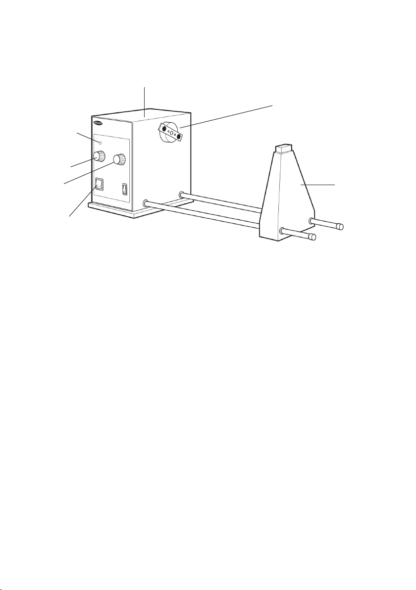
Z Control
Speed
Control
Drive unit
Drum fixing
Timer
Mains On/Off
Fig. 1: STR4 Drive unit
Rotator
STR4
Instructions for use
Support
column
Introduction
Thank you for purchasing this piece of Stuart
equipment. To get the best performance from
the equipment and for your own safety, please
read these instructions carefully before use.
Before discarding the packaging check that all
parts are present and correct.
This equipment is designed to operate under the
following conditions:
• For indoor use only
• Use in a well ventilated area
• Ambient temperature range +5ºC to +40ºC
• Altitude to 2000m
• Relative humidity not exceeding 80%
• Mains supply fluctuation not exceeding 10%
• Over-voltage category II IEC60364-4-443
• Pollution degree 2
If the equipment is not used in the manner
described in this manual and with accessories
other than those recommended by Stuart, the
protection provided may be impaired.
Page 3

Electrical Installation
Safety Advice Before Use
THIS EQUIPMENT MUST BE EARTHED
Before connection please ensure that the
line supply corresponds to that shown on
the rating plate.
Model Supply requirements Power
STR4 230V, 50Hz 50W
The STR4 is supplied with two mains leads
fitted with IEC plugs for connection to the
instrument. One has a U.K. 3 pin plug and the
other has a 2 pin “Shuko” plug for connection
to the mains. Choose the lead appropriate
for your electrical installation and discard the
other. Should neither lead be suitable, take
the lead with the U.K. plug and replace the
plug with a suitable alternative. This involves
cutting off the moulded plug, preparing the
cable and connecting to the re-wireable plug
in accordance with its instructions.
THIS OPERATION SHOULD ONLY BE
UNDERTAKEN BY A QUALIFIED
ELECTRICIAN
NOTE: Refer to the equipment’s rating plate to
ensure that the plug and fusing are suitable
for the voltage and wattage stated.
The wires in the mains cable are coloured as
follows:
BROWN - LIVE
BLUE - NEUTRAL
GREEN/YELLOW - EARTH
The instrument is fitted with an IEC socket at
the rear for connection of the mains lead. The
appropriate mains lead should be connected
BEFORE connection to the mains supply.
Should the mains lead need replacement, a
cable of 1mm2 of harmonised code H05W-F
connected to an IEC320 plug should be used.
IF IN DOUBT CONSULT A QUALIFIED
ELECTRICIAN
The unit should be carried using two hands.
Never move or carry the unit while it is in
use or connected to the mains supply.
General Description
The STR4 is a drive unit with variable speed
control that can be set between 6 and 60rpm.
For added convenience it also has an analogue
timer that can be set from 10 to 60 minutes.
Alternatively the unit can be set for continuous
operation. The STR4 accepts one of five
accessory drums that are designed to give
different mixing actions.
Operation
Refer to Fig. 1 to identify the parts and controls.
1. Assemble the drive unit and support
column. Ensure that the unit is not
connected to the mains supply before
assembly. Push the threaded ends of the
two connecting rods through the holes in
the support column and locate them into
the corresponding two holes in the drive
unit. Screw each connecting rod firmly into
the drive unit.
2. Place the apparatus on a firm, level surface.
3. Attach the left hand fixing of the drum to
the drum fixing on the drive unit.
4. Adjust the lateral position of the support
column so that it is at the correct distance
to accommodate the length of the drum
shaft and secure in place with the thumb
screw at the back.
5. Switch the mains On/Off and motor On/Off
switches to On.
6. Turn the speed control knob until the
desired rotation is seen.
7. For continuous operation, set the timer
knob to Manual.
8. In order to mix for a given time, set the
timer knob to the required time in minutes.
When the set time is over, the unit will stop
the rotation
Page 4
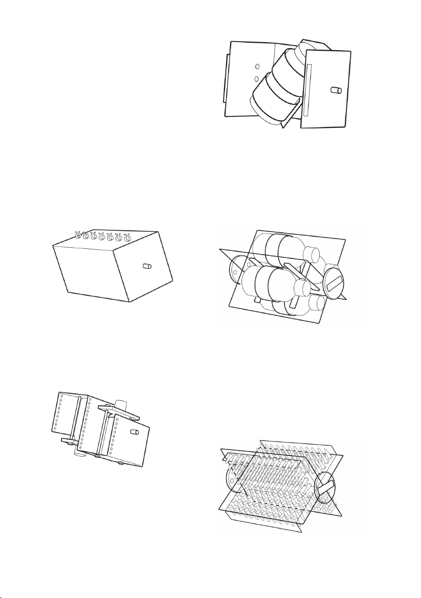
Accessory Drums
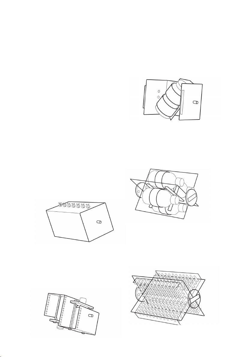
STR4/1: Designed for rotating tubes in an
end-over-end movement. The STR4/1
consists of a square metal drum which can
accommodate up to four plates fitted with
clips for various size tubes.
All clip plates are interchangeable and may be
fitted to any face of the drum. To fit the clip
plate to the drum, insert the locking pins into
the holes on any one face. Ensure that the
button on the left hand end face of the drum
is pressed in, flush with the drum. Press the
clip plates well into the drum then push the
button on the right hand face of the drum
inwards to lock the clip plate in position.
Fig. 2: STR4/1
Fig. 4: STR4/3
STR4/4: Consists of a four segment Perspex®
cradle. Each segment is fitted with a fully
adjustable Velcro® strap to hold bottles and
other containers up to 120mm in diameter
and 300mm in length.
SRT4/2: Designed to hold two x 250ml flasks
or reagent bottles for end-over-end mixing.
The vessels are securely held in place by a
collar that fits around the neck of the flask or
bottle and is secured by two washers.
Fig. 3: STR4/2
STR4/3: Designed to hold a single vessel at
a 45º angle so that it is rolled and turned
end-over-end at the same time, resulting in a
vigorous figure of 8 mixing action. The vessel
is held firmly in place by strong Velcro® straps.
The maximum vessel size is approximately
200mm in length, 120mm diameter.
Fig. 5: STR4/4
STR4/5: Designed for thorough end-over-end
mixing of 1.5ml microcentrifuge tubes. STR4/5
includes 4 racks, each of which can
accommodate up to 60 tubes. Individual racks
are easily removed by removing a locking knob
and sliding the rack out of the cradle.
Fig. 6: STR4/5
Page 5

Maintenance & Servicing
Spares and Accessories
WARNING: Ensure the unit
is disconnected from the mains
electricity supply before attempting
maintenance or servicing.
Periodically clean the instrument using a damp
cloth and mild detergent solution. Do not use
harsh or abrasive cleaning agents.
Any repairs or replacement of parts MUST
be undertaken by suitably qualified
personnel.
For a comprehensive list of parts required by
service engineers conducting internal repairs,
please contact the Service Department,
quoting both the model number and serial
number:
E-mail: service@bibby-scientific.com
Tel: +44 (0)1785 810475
Fax: +44 (0)1785 810471
Only spare parts supplied or specified by
Stuart or its agents should be used. Fitting
of non-approved parts may affect the
performance of the safety features
designed into the instrument. If in any
doubt, please contact the Service Department
of Bibby Scientific Ltd. or the point of sale.
For any other technical enquiries, please
contact the Technical Support Department:
E-mail: stuarthelp@bibby-scientific.com
Tel: +44 (0)1785 810433.
Description Catalogue Number
Drum to hold test tube
clip plates STR4/1
Clip plates for 12 x 12mm
tubes (pair) STR1/1
Clip plates for 10 x 16mm
tubes (pair) STR1/2
Clip plates for 8 x 19mm
tubes (pair) STR1/3
Clip plates for 7 x 24mm
tubes (pair) STR1/4
Drum with two platforms
to hold flasks or bottles STR4/2
Drum with figure of 8
mixing action STR4/3
Drum with four segment
cradle for bottles STR4/4
Drum with four segment
cradle for microfuge tubes STR4/5
Spare rack for 60 x 1.5ml
microfuge tubes SW2/1
Warranty
Stuart warrants this equipment to be free from
defects in material and workmanship, when
used under normal laboratory conditions, for
a period of three (3) years. In the event of a
justified claim, Stuart will replace any defective
component or replace the unit free of charge.
This warranty does NOT apply if damage is
caused by fire, accident, misuse, neglect,
incorrect adjustment or repair, damage
caused by installation, adaptation,
modification, fitting of non-approved parts or
repair by unauthorised personnel.
Bibby Scientific Ltd.
Beacon Road, Stone, Staffordshire
ST15 0SA
United Kingdom
Tel: +44 (0)1785 812121
Fax: +44 (0)1785 813748
E-mail: equipment@bibby-scientific.com
www.stuart-equipment.com
Page 6

Technical Specification
STR4
Rotation speed 6 to 60rpm
Timer 10 to 60 minutes or continuous
Maximum load 3kg
Power 230V, 50/60Hz
Dimensions (w x d x h) mm 650 x 250 x 250mm
Net weight 6.4kg
Electrical supply 230V, 50Hz, 50W
Page 7
Deutsch
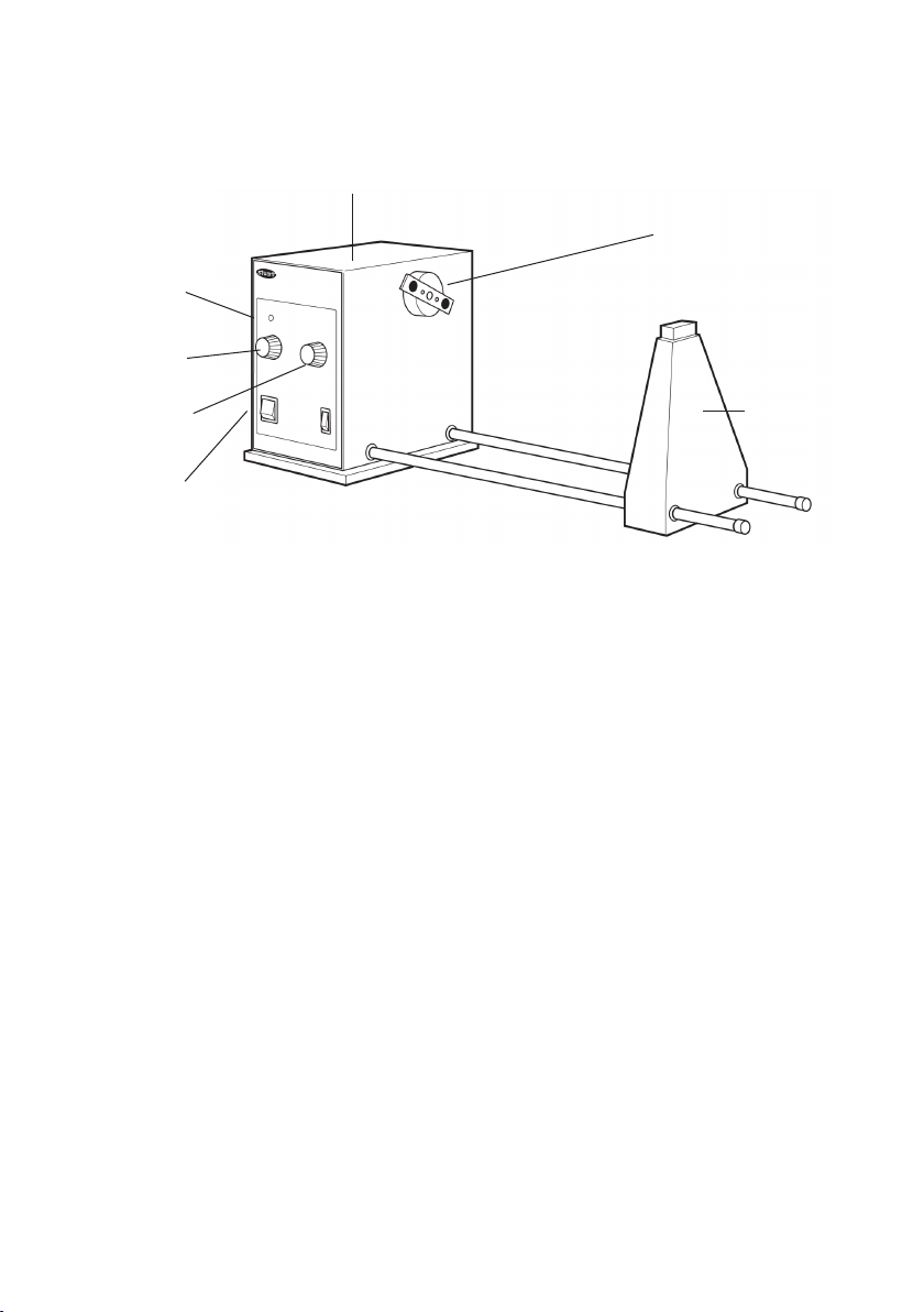
Z-Steuerung
Drehzahlregelung
Antriebseinheit
Trommelbefestigung
Zeitschaltuhr
Motor Ein/Aus
Abb. 1: STR4 Drive unit Antriebseinheit
Rotator
STR4
Bedienungsanweisung
Stützsäule
Einführung
Vielen Dank, dass Sie sich für dieses StuartGerät entschieden haben. Lesen Sie bitte
vor Verwendung des Geräts gründlich diese
Gebrauchsanweisung, um das Potenzial des
Geräts optimal nutzen zu können und Ihre
eigene Sicherheit zu gewährleisten. Überprüfen
Sie bitte vor dem Entsorgen der Verpackung,
dass alle Teile vorhanden und in Ordnung sind.
Dieses Gerät ist für den Betrieb unter folgenden
Bedingungen ausgelegt:
• Nur für den Betrieb in Innenräumen
• Betrieb in gut belüfteten Räumen
• Umgebungstemperatur +5ºC bis +40ºC
• Höhenlagen bis 2000 m
• Relative Luftfeuchtigkeit maximal 80 %
• Schwankungen in der Stromversorgung
maximal 10 %
• Überspannungskategorie II IEC60364-4-443
• Verschmutzungsgrad
Das Gerät darf nur in der hier beschriebenen
Weise und mit Zubehör betrieben werden, das
von Stuart empfohlen wurde; andernfalls kann
der gewährte Schutz beeinträchtigt werden.
Page 8

Elektrische Installation
DIESES GERÄT MUSS GEERDET WERDEN
Vergewissern Sie sich vor dem Anschluss,
dass die Netzspannung den Angaben auf
dem Geräteschild entspricht.
Erforderliche
Modell Spannungsversorgung Spannungsversorgung
STR4 230V, 50Hz 50W
Der STR4 ist mit zwei Netzkabeln mit
IEC-Steckern für den Anschluss an das
Gerät ausgestattet. Zum Anschluss an die
Stromversorgung ist ein Kabel mit einem
3-poligen GB-Stecker, das andere mit einem
2-poligen Schukostecker versehen. Wählen Sie
das für Ihre Elektroinstallation geeignete Kabel
und entfernen Sie das andere. Sollten beide
Kabel ungeeignet sein, entfernen Sie den GBStecker und ersetzen Sie ihn durch eine geeignete
Alternative. Dazu müssen Sie den Formstecker
abschneiden, das Kabel vorbereiten und den
verdrahtbaren Stecker gemäß den Anweisungen
anschließen.
DIESER VORGANG DARF NUR VON
EINEM QUALIFIZIERTEN ELEKTRIKER
DURCHGEFÜHRT WERDEN.
HINWEIS: Prüfen Sie anhand des Geräteschilds,
dass Stecker und Sicherungen für die
angegebene Spannungs- und Stromstärke
geeignet sind.
Die Leiter des Netzkabels sind wie folgt
farbcodiert:
BRAUN - SPANNUNGSFÜHREND
BLAU - NEUTRAL
GRÜN/GELB - MASSE
Auf der Rückseite des Instruments befindet
sich eine IEC-Buchse für den Anschluss des
Netzkabels. Der entsprechende Netzstromleiter
muss verbunden werden, BEVOR der Anschluss
an die Stromversorgung erfolgt.
Sollte ein Austausch des Netzkabels erforderlich
sein, muss ein Kabel mit einem Querschnitt von 1
mm2 mit dem harmonisierten Code H05W-F und
einem IEC320-Stecker verwendet werden.
BEI ZWEIFELN WENDEN SIE SICH AN EINEN
QUALIFIZIERTEN ELEKTRIKER
Vor dem Einsatz zu beachtende
Sicherheitshinweise
• Das Gerät ist stets mit beiden Händen zu tragen.
• Transportieren Sie das Gerät nicht, wenn es
in Betrieb oder an die Netzstromversorgung
angeschlossen ist.
Allgemeine Beschreibung
Der STR4 ist eine Antriebseinheit mit variabler
Drehzahlregelung zwischen 6 und 60 U/Min. Die
Bedienung wird durch eine analoge Zeitschaltuhr
mit einem Einstellbereich von 10 bis 60 Minuten
vereinfacht. Alternativ ist auch ein Dauerbetrieb
möglich. Der STR4 ist mit fünf verschiedenen
Zubehörtrommeln für jeweils verschiedene
Mischvorgänge kompatibel.
Betrieb
Zur Identifizierung der Komponenten und
Bedienelemente siehe Abbildung 1.
1. Die Antriebseinheit und die Stützsäule
montieren. Die Gewindeenden der beiden
Verbindungsstangen durch die Öffnungen
in der Stützsäule und in die beiden
entsprechenden Öffnungen in der
Antriebseinheit führen. Beide
Verbindungsstangen fest in der
Antriebseinheit verschrauben.
2. Das Gerät auf eine flache, ebene Fläche
stellen.
3. Die linke Befestigung der Trommel an
der Trommelbefestigung der Antriebseinheit
anbringen.
4. Die seitliche Position der Stützsäule
so einstellen, dass der Abstand ausreicht, um
die gesamte Länge der Trommelwelle
aufzunehmen. Anschließend durch Festziehen
der Flügelschraube auf der Rückseite sichern.
5. Den Netzschalter und den Schalter für
Motorbetrieb auf „On“ stellen.
6. Den Drehzahlregelungsknopf auf die
gewünschte Rotationsgeschwindigkeit einstellen.
7. Für Dauerbetrieb den Knopf der Zeitschaltuhr auf
manuellen Betrieb stellen.
Page 9
8. Um die Dauer eines Mischvorgangs
festzulegen, den Knopf der Zeitschaltuhr auf
die gewünschte Zeit in Minuten einstellen. Nach
Ablauf der eingestellten Zeit stoppt der Rotator.
9. Z-Steuerung: Einstellung der niedrigsten
Drehzahl. Den Drehzahlregelungsknopf
auf 1 stellen und die Z-Steuerung justieren,
bis die Trommel sich mit der gewünschten
Geschwindigkeit dreht. Diese Geschwindigkeit
wird jedes Mal erreicht, wenn der
Regelungsknopf auf 1 gestellt wird.
Zubehörtrommeln
STR4/1: Für überkopf rotierende Röhrchen.
Der STR4/1 besteht aus einer quadratischen
Metalltrommel zur Aufnahme von bis zu vier
Platten mit Halteclips für Röhrchen verschiedener
Größen. Die Halterungsplatten sind
untereinander austauschbar und können an einer
beliebigen Trommelseite befestigt werden. Zur
Befestigung der Halterungsplatte an der Trommel
die Halterungsstifte in die Öffnungen auf einer
der Trommelseiten einführen. Sicherstellen,
dass der Knopf an der linken Endfläche der
Trommel nach innen gedrückt wird, bis er mit
der Trommel fluchtet. Die Halterungsplatten fest
in die Trommel drücken und anschließend den
Knopf auf der rechten Trommelseite nach innen
drücken, um die Halterungsplatten zu sichern.
Abb. 3: STR4/2
STR4/3: Zur Aufnahme eines einzelnen Gefäßes
in einem Winkel von 45º. Die gleichzeitige
Rotation in 8er-Form und überkopf gewährleistet
ein rigoroses Mischen der Substanzen. Das Gefäß
wird durch widerstandsfähige Velcro®-Bänder
gesichert. Maximale Behältergröße: Ca. 200 mm
Länge, 120 mm Durchmesser.
Abb. 4: STR4/3
STR4/4: Perspex®-Aufnahme mit 4 Segmenten.
Jedes Segment ist mit einem flexibel einstellbaren
Velcro®-Band ausgestattet, das Flaschen und
andere Gefäße bis 120 mm Durchmesser und
300 mm Länge sicher in Position hält.
Abb. 2: STR4/1 mit STR1/4.
SRT4/2: : Zur Aufnahme von 2 x 250 ml Kolben
oder Reagenzflaschen für Überkopf-Rotation.
Die Gefäße werden durch einen um den Kolbenoder Flaschenhals geführten und mit zwei
Unterlegscheiben gesicherten Ring in Position
gehalten.
Abb. 3: STR4/2
Abb. 5: STR4/4
STR4/5: Für gründliches Überkopf-Mischen
von 1,5 ml Mikrozentrifugenröhrchen. STR4/5
beinhaltet 4 Röhrchenständer für je 60 Röhrchen.
Die einzelnen Röhrchenständer können nach
Entfernen eines Sicherungsknopfs bequem aus
der Aufnahme herausgeschoben werden.
Abb. 6: STR4/5
Page 10

Wartung und Service
Ersatzteile und Zubehör
WARNUNG: Stellen Sie sicher, dass
das Gerät von der Stromversorgung
getrennt ist, bevor Sie Service- oder
Wartungsarbeiten durchführen.
Reinigen Sie das Gerät in regelmäßigen
Abständen mit einem feuchten Lappen und einer
milden Reinigungslösung. Verwenden Sie keine
aggressiven oder scheuernden Reinigungsmittel.
Reparaturen und ein Austausch von Teilen
MÜSSEN von entsprechend qualifiziertem
Personal durchgeführt werden.
Um eine umfassende Ersatzteilliste anzufordern,
die Servicetechniker für interne Reparaturen
benötigen, wenden Sie sich bitte unter
Angabe von Modell und Seriennummer an die
Serviceabteilung unter:
E-mail: service@bibby-scientific.com
Tel.: +44 (0)1785 810475
Fax: +44 (0)1785 810471
Es dürfen nur Ersatzteile verwendet werden,
die von Stuart oder seinen Vertretern
geliefert oder angegeben werden. Die
Verwendung nicht genehmigter Teile kann
die Leistung der in das Gerät integrierten
Sicherheitseinrichtungen beeinträchtigen. Bei
Fragen oder Zweifeln wenden Sie sich bitte an die
Serviceabteilung von Bibby Scientific Ltd. oder an
die Verkaufsstelle.
Sonstige technische Anfragen richten Sie bitte an
die technische Support-Abteilung:
E-Mail: stuarthelp@bibby-scientific.com,
Tel.: +44 (0)1785 810433.
Beschreibung Katalog-Nummer
Trommel zur Aufnahme von
Halterungsplatten für Teströhrchen STR4/1
Halterungsplatten für 12 x 12 mm
Röhrchen (2 Stck) STR1/1
Halterungsplatten für 10 x 16 mm
Röhrchen (2 Stck) STR1/2
Halterungsplatten für 8 x 19 mm
Röhrchen (2 Stck) STR1/3
Halterungsplatten für 7 x 24 mm
Röhrchen (2 Stck) STR1/4
Trommel mit zwei Plattformen zur
Aufnahme von Kolben oder Flaschen STR4/2
Trommel für Rotation in 8er-Form STR4/3
Trommel mit 4-Segment-Aufnahme
für Flaschen STR4/4
Trommel mit 4-Segment-Aufnahme für
Microfuge-Röhrchen STR4/5
Ersatzständer für 60 x 1,5 ml
Microfuge-Röhrchen SW2/1
Garantie
Stuart garantiert, dass dieses Gerät frei von
Material- und Herstellungsfehlern ist. Bei
Einsatz unter normalen Laborbedingungen wird
eine Garantie von drei (3) Jahren gewährt. Bei
einem berechtigten Garantieanspruch ersetzt
Stuart defekte Bauteile oder das gesamte Gerät
kostenlos. Diese Garantie gilt NICHT, wenn
Schäden durch Feuer, Unfall, Missbrauch,
Nachlässigkeit, falsche Einstellung oder Reparatur,
durch Installation, Adaption, Modifikation,
Montage nicht genehmigter Teile oder Reparatur
durch nicht autorisierte Personen entstanden
sind.
Bibby Scientific Ltd.
Beacon Road,
Stone, Staffordshire
ST15 0SA
Großbritannien
Tel.: +44 (0) 1785 812121
Fax: +44 (0) 1785 813748
E-Mail: equipment@bibby-scientific.com
www.stuart-equipment.com
Page 11

Technische Daten
STR4
Rotationsgeschwindigkeit 6 bis 60 U/Min
Zeitschaltuhr 10 bis 60 Minuten oder Dauerbetrieb
Maximale Last 3kg
Abmessungen (B x T x H) 650 x 250 x 250mm
Nettogewicht 6.4kg
Stromversorgung 230V, 50Hz, 50W
Page 12

This product meets the applicable
EC harmonized standards for radio
frequency interference and may be
expected not to interfere with, or be affected
by, other equipment with similar qualifications.
We cannot be sure that other equipment
used in its vicinity will meet these standards
and so we cannot guarantee that interference
will not occur in practice. Where there is a
possibility that injury, damage or loss might occur
if equipment malfunctions due to radio frequency
interference, or for general advice before use,
contact the Technical Department of Bibby
Scientific Ltd.
Page 13
INSPECTION REPORT
MODEL SRT4
ELECTRICAL SAFETY
1. Earth continuity
2. Insulation
3. Flash test
FUNCTIONAL
1. Indicators
2. Speed/temperature
3. Visual acceptance
QUALITY CONTROL INSPECTOR
Bibby Scientific Ltd
Beacon Road Stone
Staffordshire ST15 0SA
United Kingdom
Tel: +44 (0)1785 812121
Fax: +44 (0)1785 810471
e-mail: info@bibby-scientific.com
www.bibby-scientific.com
Bibby Scientific France SAS
ZI du Rocher Vert - BP 79
77793 Nemours Cedex
France
Tel: +33 1 64 45 13 13
Fax: +33 1 64 45 13 00
e-mail: bsf@bibby-scientific.fr
www.bibby-scientific.com
Bibby Scientific US Ltd
3 Terri Lane Suite 10
Burlington NJ 08016
USA
Tel: 800-225-9243
Fax: 609-589-2571
www.bibby-scientific.com
Bibby Scientific Italia Srl
Via Alcide de Gasperi 56
20077 Riozzo di Cerro al Lambro
Milano Italia
Tel: +39 (0)2 98230679
Fax: +39 (0)2 98230211
e-mail: marketing@bibby-scientific.it
www.bibby-scientific.it
Bibby Scientific (Asia) Ltd
Room 607 Yen Sheng Centre
64 Hoi Yuen Road Kwun Tong
Kowloon Hong Kong
Tel: +852 3583 1581
Fax: +852 3583 1580
e-mail bibby@bibby-scientificasia.com
www.bibby-scientificasia.com
 Loading...