

Page 1
Do not touch the
cooling fin wit h your
bare hands .
It may cut your fingers.
WARNI NG
Use extre me caut ion
when usi ng
flammabl e and
ignitabl e solve nt.
Fire ha zard
Touching th e
cooling fins ma y
cause bu rns.
Hot sur face
CAUTION
CAUTION
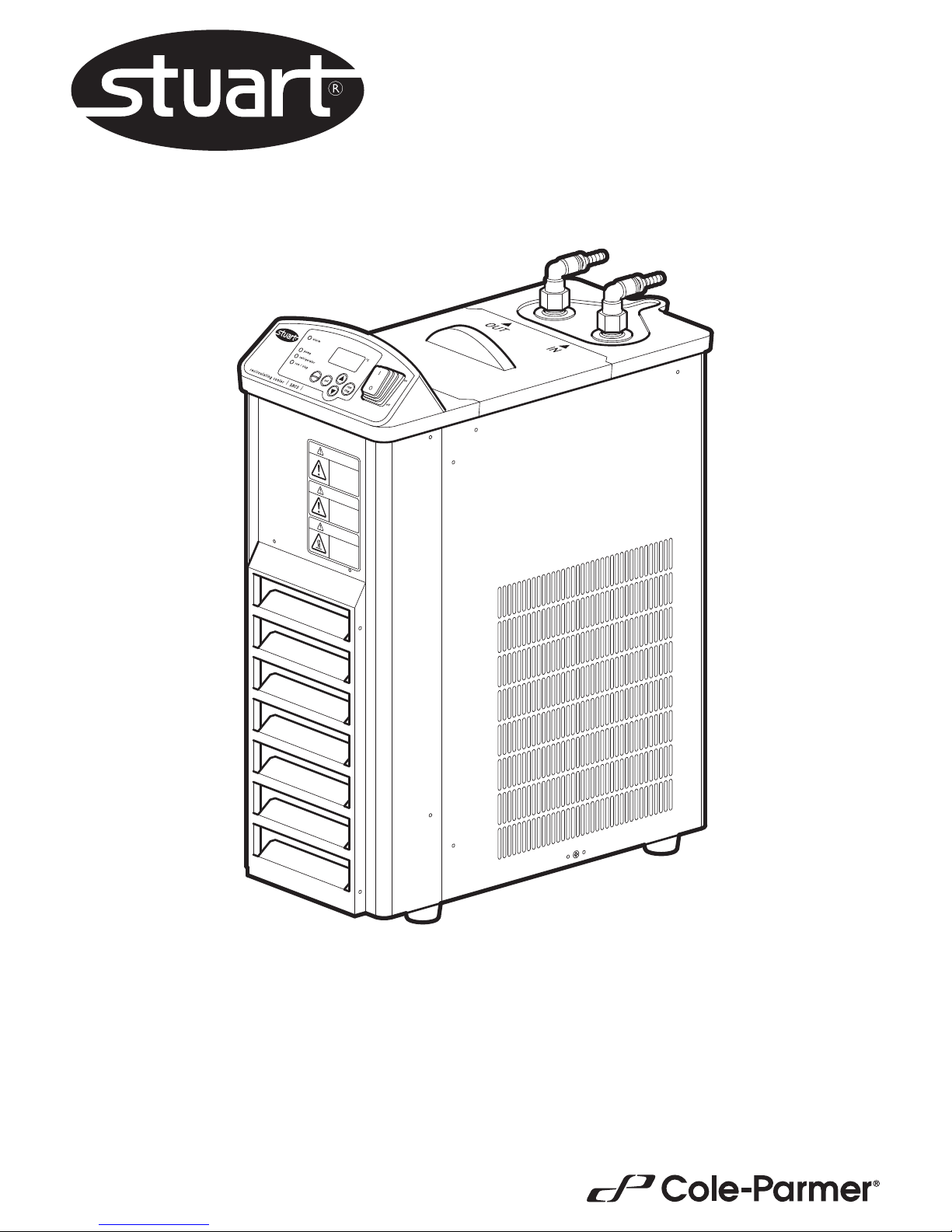
Recirculating Cooler
SRC5
Instruction Manual
STU0004 / Version 1.0
Page 2

2
Section 1 - Introduction
Thank you for purchasing this Stuart product. To get the best performance from the equipment, and
for your own safety, please read these instructions carefully before use.
If the equipment is not used in the manner described in this manual and with accessories other than
those recommended by the manufacturer, the protection provided may be impaired.
1.1 General Description
A Recirculating Cooler offers a powerful cooling for an external device. By accurately controlling the temperature
of your cooling medium down to -20°C, efciency of operations such as condensing can be greatly improved. A
recirculating cooler is not only much more powerful than conventional water cooling, but is also an ideal
alternative when water consumption is an issue for economical, environmental or practical reasons.
The SRC5 provides a powerful cooler with a compact footprint suitable for mounting on or under a bench. The LED
digital display clearly shows the current temperature of the cooling medium to ±2°C, while the set temperature is
revealed by a one button press.
The unit has a dedicated drain for easy emptying and cleaning. It also incorporates a built in safety alarm to indicate
an overload relay for the refrigeration unit. A dust lter is incorporated and can be accessed without tools via the
hinged front panel.
1.2 Important Safety Advice
Users should be aware of the following safety advice:
❖ SHOCK HAZARDS OR UNSAFE PRACTICES ARE DANGEROUS as they can cause severe personal injury, re
or death.
❖ DO NOT use combustible substances near hot objects.
❖ DO NOT cover any of the ventilation panels.
❖ DO NOT use the equipment in hazardous atmospheres.
❖ DO NOT operate or handle any part of the equipment with wet hands or use on surfaces that may become ooded.
❖ NEVER move the equipment while still connected to the power supply.
❖ HIGH TEMPERATURES ARE DANGEROUS as they can cause serious burns to operators and ignite combustible
material.
❖ USE CARE AND WEAR PROTECTIVE GLOVES TO PROTECT HANDS.
❖ NEVER lift or carry the equipment during operation.
❖ DO NOT position the equipment unit so that it is difcult to disconnect from the mains supply using the mains
plug.
❖ The mains outlet socket used should be located close to the equipment and readily identiable and accessible
to users.
❖ DO NOT leave equipment switched on and it is not recommended to leave any heating apparatus unattended
during operation.
❖ The equipment should be transported and installed with a minimum of two people.
❖ The equipment is tted with a power outage recovery mode. In case of mains interruption you can choose if
you want the recirculating cooler to continue or stop once the power is restored, see section 4.3.
❖ DO NOT use the equipment with distilled or deionised water
Page 3
3
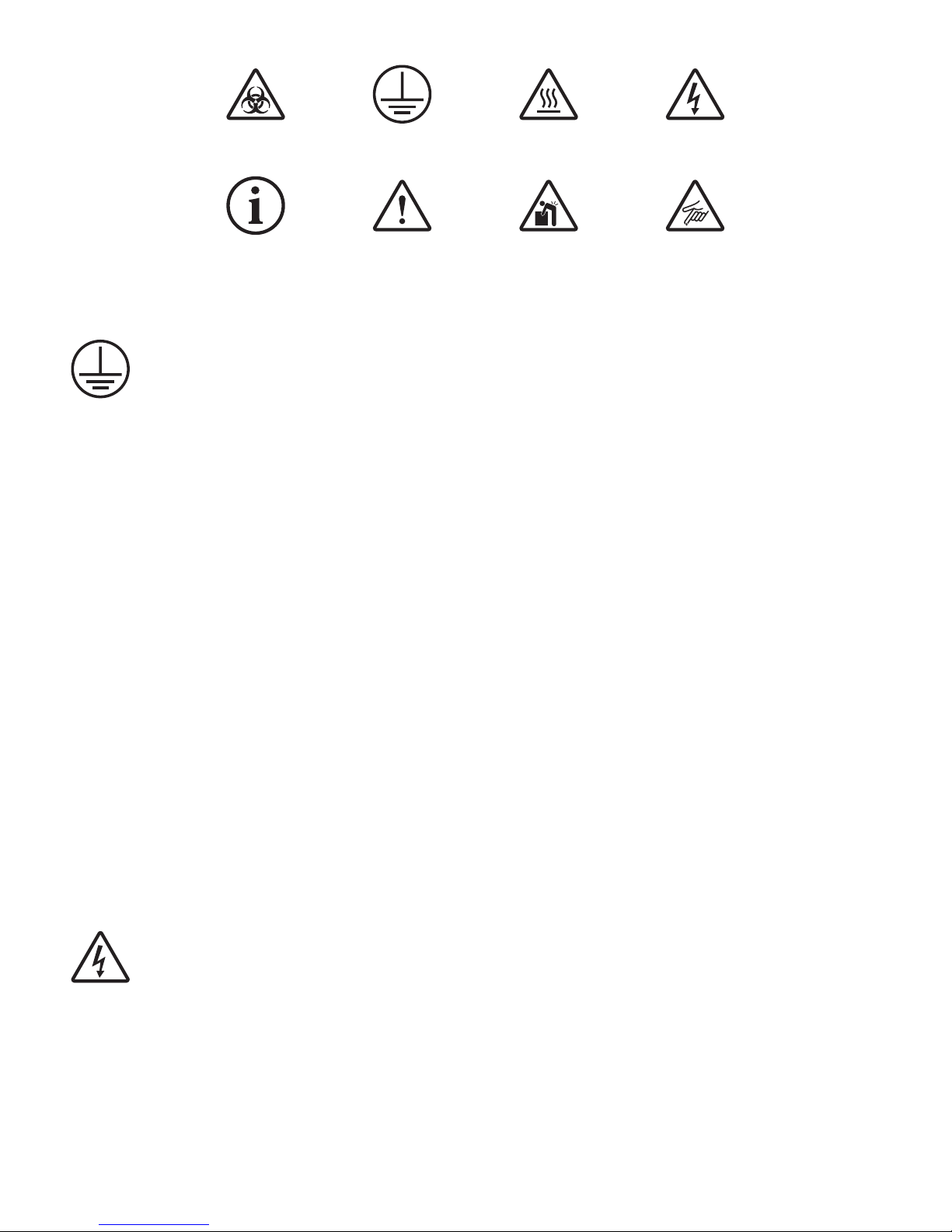
1.3 Symbols Dened
1.4 Electrical Requirements
THIS INSTRUMENT MUST BE GROUNDED
Before connection please ensure that the line supply corresponds to the power requirements below:
Model Power Supply requirements
SRC5 450 W 230 V ~ 50Hz
The equipment is provided with a power supply unit and three power cables consisting of a UK 3-pin and a “Schuko”
2-pin plug for 230 V installation.
Choose the power cable appropriate for your electrical installation and discard the others. Should none of the power
cables be suitable for connecting to the power supply, replace the plug with a suitable alternative.
THIS OPERATION SHOULD ONLY BE UNDERTAKEN BY A QUALIFIED ELECTRICIAN.
NOTE: Refer to the equipment rating plate to ensure that the plug and fusing are suitable for the voltage and
wattage stated. The wires in the mains cable are as follows:
230 V a.c.
HOT/LIVE - BROWN
NEUTRAL - BLUE
EARTH - GREEN/YELLOW
The appropriate power cable and power adaptor combination should be connected to the equipment BEFORE
connection to the mains supply.
Should the mains lead require replacement please contact [email protected].
IF IN DOUBT CONSULT A QUALIFIED ELECTRICIAN
WARNING
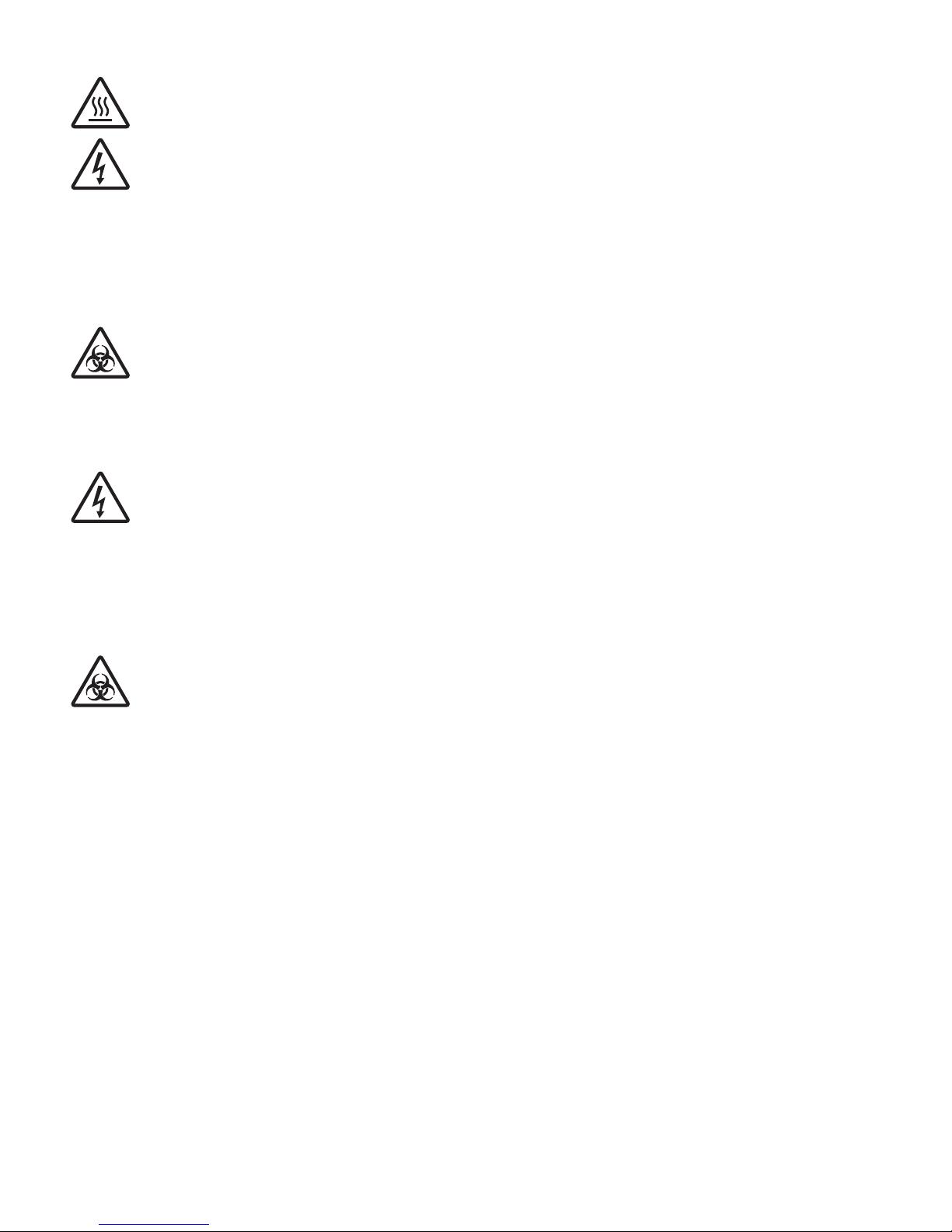
EARTH RISK OF
ELECTRIC SHOCK
BIOHAZARD HOT SURFACE
INFORMATION HEAVY OBJECT
2 PERSON LIFT
REQUIRED
SHARP OBJECT
Page 4
4
Section 2 - Specication
NOTE: Results can vary depending on environmental conditions, power supply voltage, solvent type and hose
specication etc.
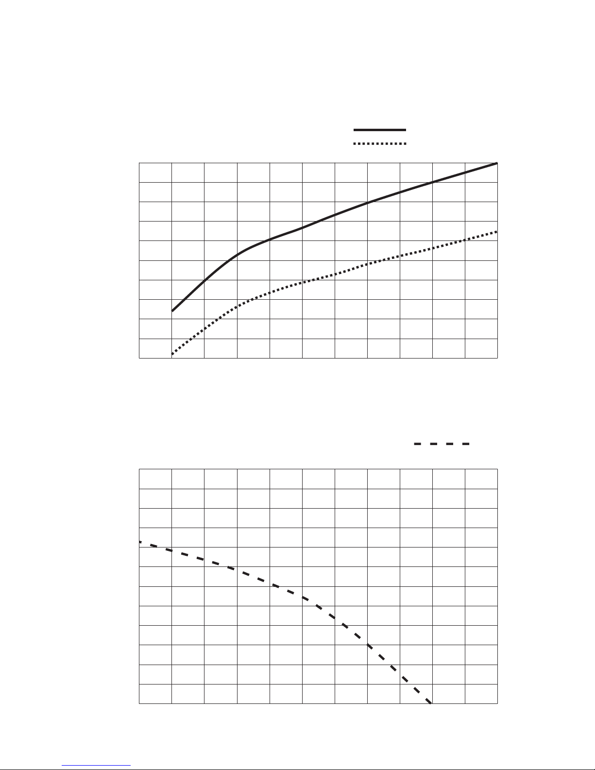
2.1 Cooling capability curve (Reference data)
2.2 Circulation capability (Reference data)
Condition
• Supply voltage : AC220V, 50Hz
• Circulation rate : max.
Room temp. 20ºC
Room temp. 35ºC
0
100
200
300
400
500
550
Cooling capability (W)
-20
Liquid temperature (ºC)
-10 0 10 20 30
0
0
1
2
3
4
5
6
1 2 3 4 5 6 7 8 9 10 11
Condition
• Supply voltage : AC220V, 50Hz
• Liquid temperature : 20ºC
50Hz
Flow volume (ℓ/min)
Lifting height (m)
Page 5

5
Section 3 - Installation
3.1 Unpacking
Before discarding the packaging check that all parts are present and correct.
1 SRC5
2 Bath cover
3 UK power lead
4 Euro power lead
5 Instruction manual
6 Warranty card
7 Spare fuses x2
Do not touch the
cooling f in wit h your
bare hands .
It may cut your fingers.
WARNI NG
Use extre me caut ion
when usin g
flammable and
ignitable solve nt.
Fire haz ard
Touching th e
cooling f ins may
cause bur ns.
Hot surf ace
CAUTION
CAUTION
1
2
3
4
5
6 7
Page 6
6
3.2 Installation Conditions
This equipment is designed to operate safely under the following conditions:
❖ For indoor use only
❖ Use in a well ventilated area
❖ Ambient temperature range 5°C to 35°C (41°F to 95°F)
❖ Altitude to 2000m (6500 ft)
❖ Relative humidity not exceeding 75% decreasing to 30% and free from condensation
❖ Mains supply uctuations not exceeding 10% of nominal
❖ Overvoltage category II IEC60364-4-443
❖ Pollution degree 2 IEC664
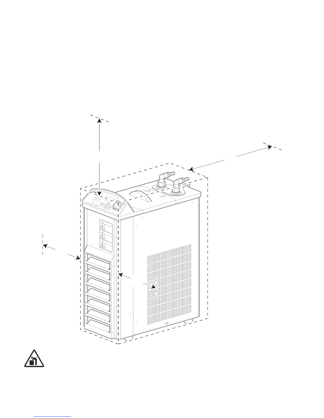
❖ Use with the minimum distance shown from walls and other items as shown below.
CAUTION: Two person lift required. This equipment weighs 28kg and should be transported
and installed with a minimum of two people.
Place the equipment on a clean, rm, level surface which is free from drafts and away from direct sun light. Avoid
installation on a slippery surface or on a surface prone to vibration or on a surface prone to ooding. You will require
easy access to power, water supply and drain and vacuum line to use your recirculating cooler.
Do not tou ch th e
cooling fin with y our
bare hands.
It may cut your fingers.
WARNIN G
Use extreme caution
when using
flammable a nd
ignitable s olvent.
Fire hazar d
Touching the
cooling fin s may
cause burns .
Hot surfac e
CAUTION
CAUTION
200
mm
200
mm
300
mm
400
mm
Page 7
7
Do not touc h the
cooling fin w ith you r
bare hands.
It may cut your fingers.
WARNIN G
Use extreme ca ution
when using
flammable and
ignitable sol vent.
Fire hazard
Touching the
cooling fins may
cause burns.
Hot surface
CAUTION
CAUTION
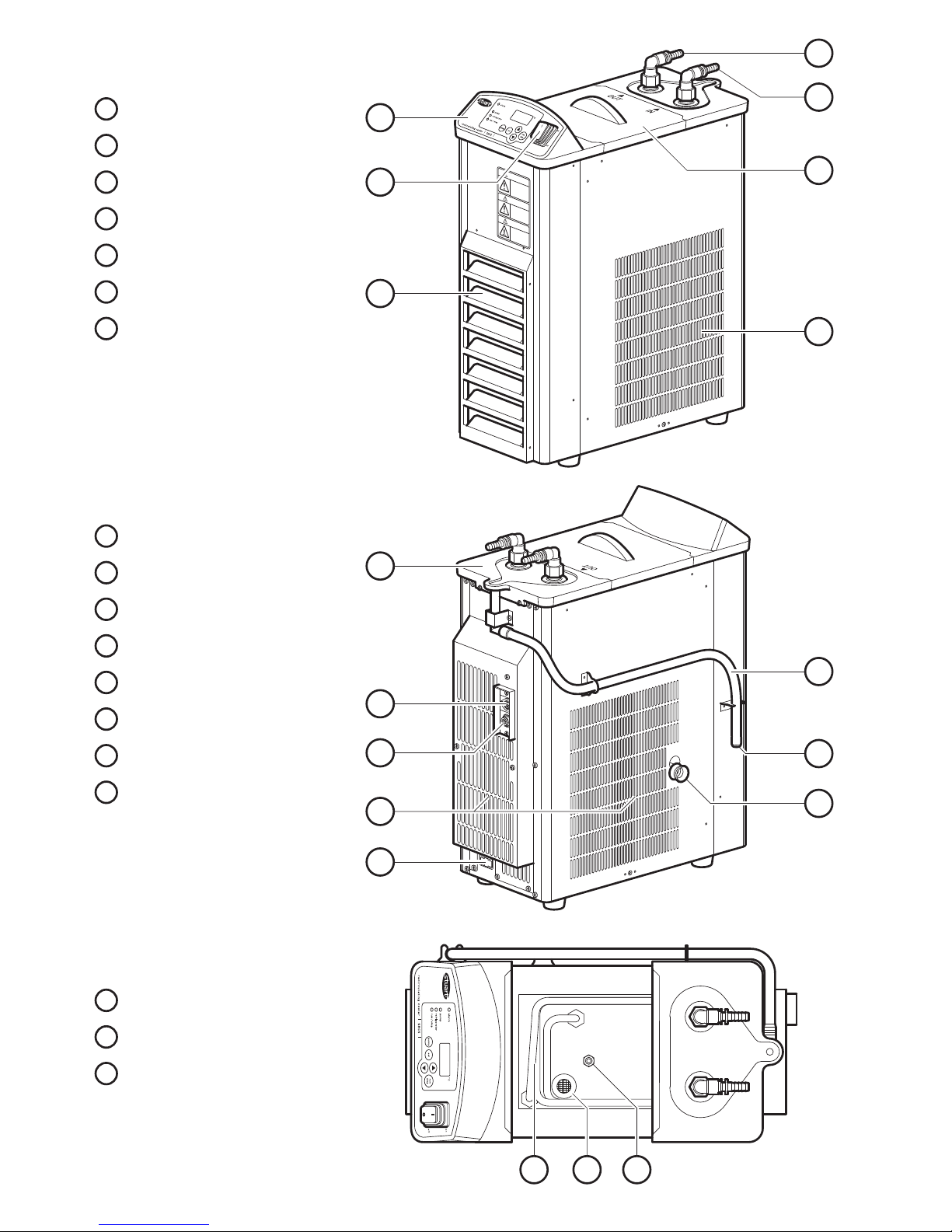
3.3 Overview
Main View
1 Control panel
2 Power switch
3 Ventilation cover
4 Water out
5 Water in
6 Bath cover
7 Ventilation
Rear View
8 Tray
9 Communication connector
10 Communication terminal
11 Ventilation
12 Fused IEC connector
13 Tray drain hose
14 Tray drain plug
15 Drain plug
Rear View
16 Cooling coil
17 Strainer
18 Temperature sensor
16
1
4
5
3
7
8
10
9
12
13
15
6
2
17 18
14
11
Page 8
8
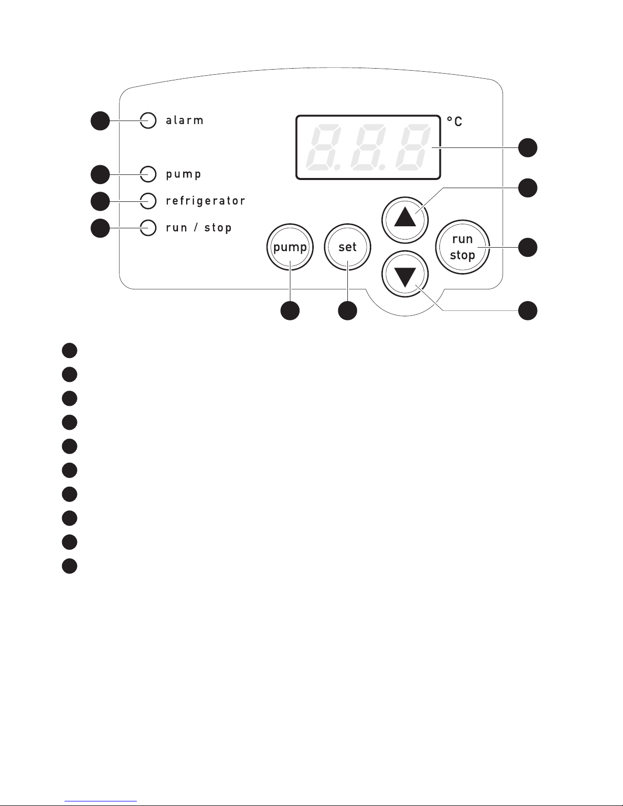
Control Panel
1 Alarm light - Comes on when an abnormal condition has been detected.
2 Pump light - Comes on when the pump is ON.
3 Refrigerator light - Comes on when the regerator is ON.
4 Run/Stop light - Comes on when temperature control is started.
5 Pump - Use to switch the pump ON/OFF.
6 Set - Use to switch between temperature setting and measurement mode. Clears alarm.
7 Display - Temperature is displayed. Alarm is displayed when an abnormal condition occurs.
8 Up key - Press to increase temperature by 1ºC. Press and hold to continually increase value.
9 Run/Stop - Use to switch between start/stop temperature control.
10 Down key - Press to decrease temperature by 1ºC. Press and hold to continually decrease value.
1
6
10
8
2
3
4
5
9
7
Page 9
9
3.4 Assembly
WARNING: DO NOT use the refrigerated cooler with distilled or deionised water.
Use tap water or softened tap water. Using distilled or deionised water could corrode the cooling coil or
circulation pump.
Use anti-freeze if you intend you use the equipment at temperatures of +7ºC and lower. Only use tap water or
softened tap to water to dilute the anti-freeze DO NOT use distilled or deionised water.
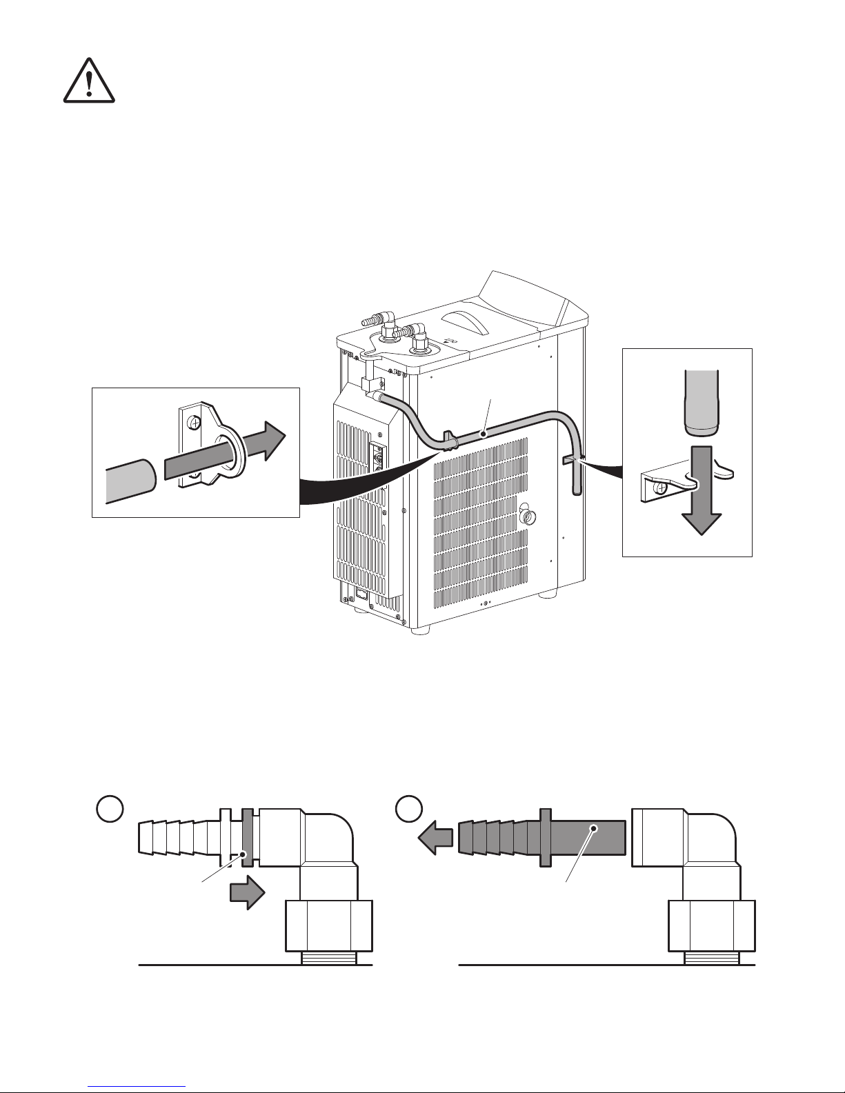
3.4.1 Step 1
Pass the Tray drain hose through the 2 metal ttings as shown. Take care not to kink, twist or squash the hose.
3.4.2 Step 2
To get the best results we recommend you connect the recirculating cooler using exible hose of 9mm I.D. and
keep hose length as short as possible.Using longer hoses than necessary can result in poor performance and could
damage your equipment. You must use hoses that are suitable for your installation. Ensure hoses are sufciently
insulated for your installation.
Remove the Water in and Water out one touch connectors from the 90º elbows. To do this, press the Elbow collar
in and pull the One touch connector to remove.
i ii
Elbow collar
Tray drain hose
One touch connector
Page 10
10
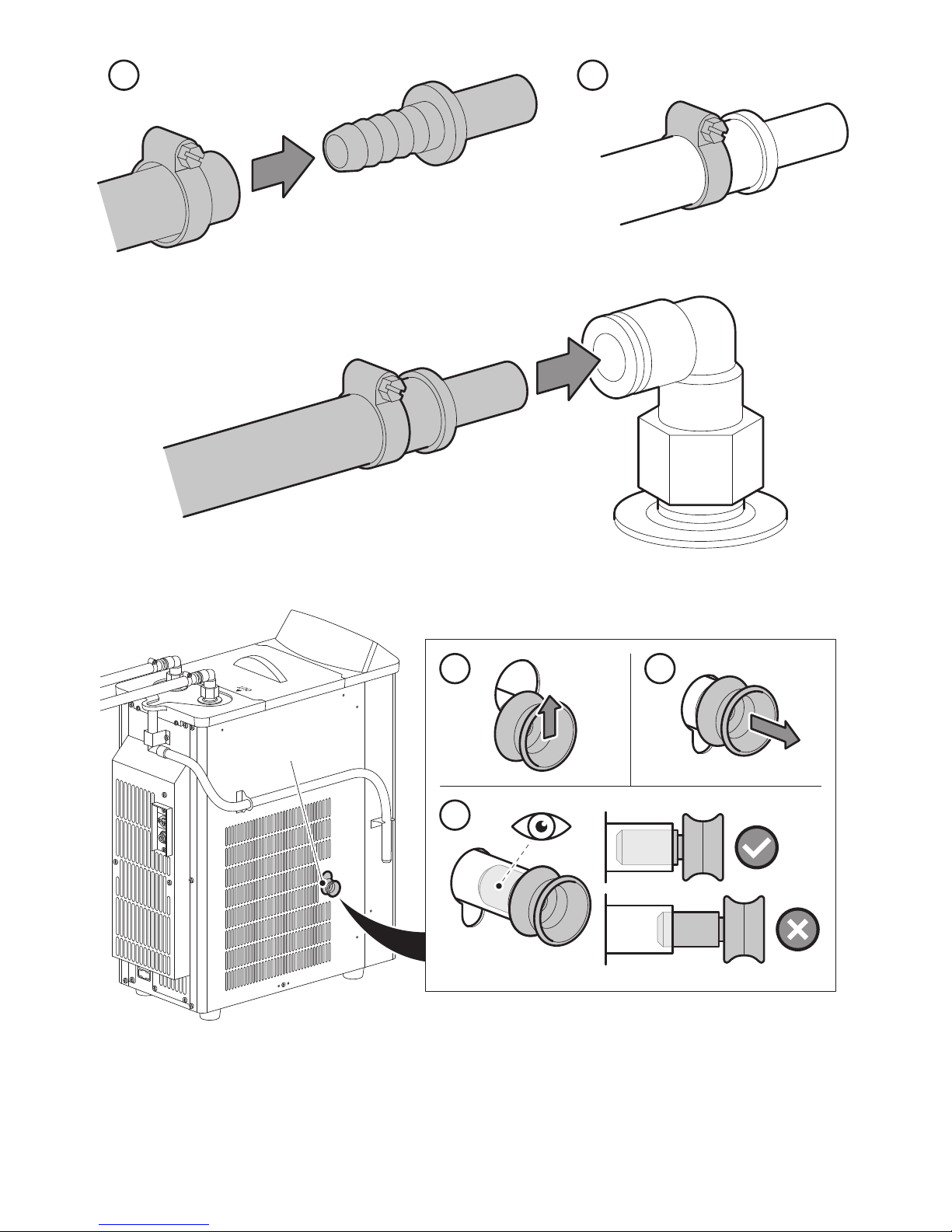
Push the hoses over the Water in and Water out one touch connectors and secure with a suitable clip.
Push the Water in and Water out one touch connectors into the correct 90º elbows.
3.4.3 Step 3
Ensure that the Drain plug is tted correctly to the drain hose before you start to ll the circulating bath.
Remove the bath cover and ll the circulating bath with your chosen liquid to a maximum of 2.7 litres.
Replace the bath cover.
3.4.4 Step 4
Ensure the power switch is OFF and connect the power lead to the recirculating cooler and then to the mains power.
i ii
iii
i ii
Drain plug
Page 11
11
Section 4 - Operation
Power outage recovery is ON when shipped.
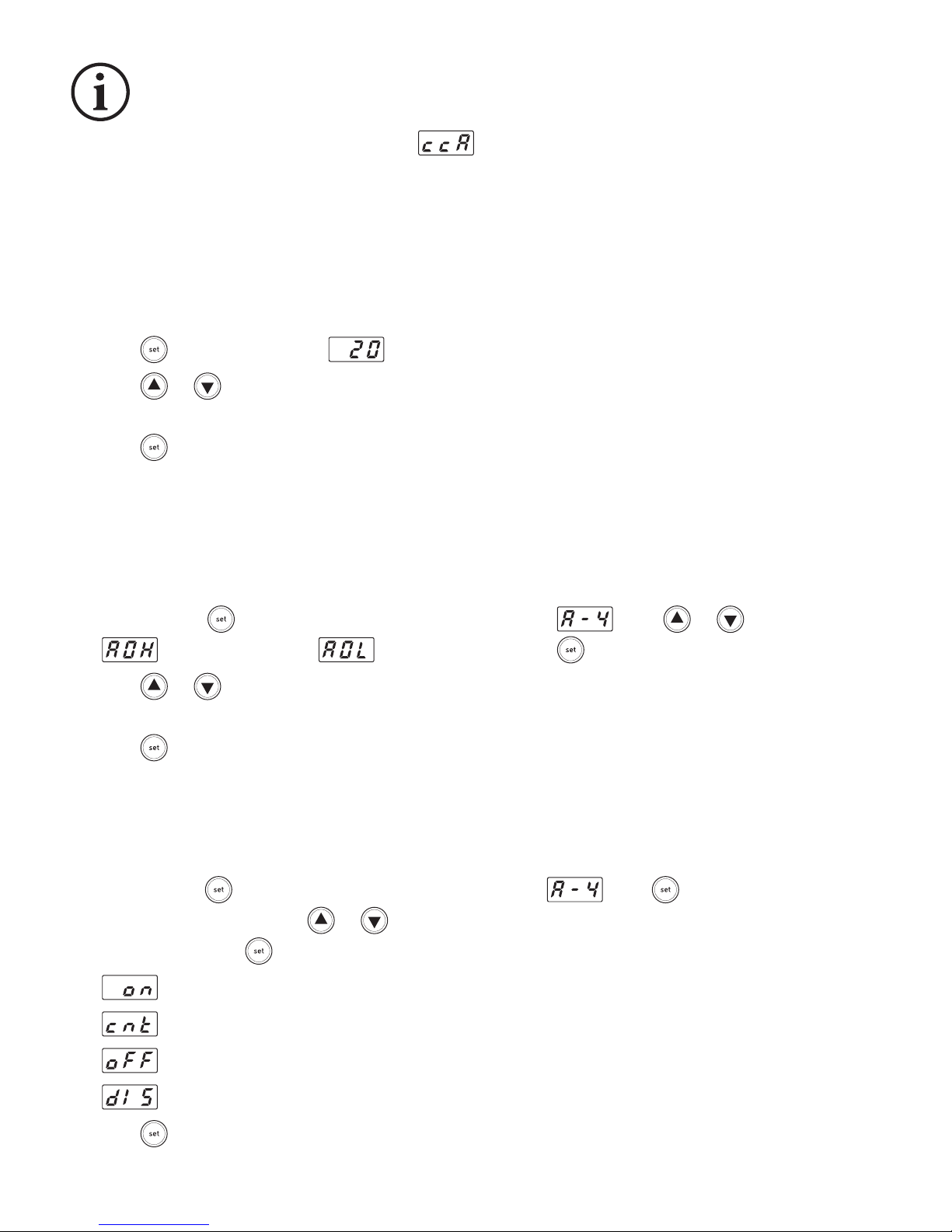
Switch the equipment ON. The display will show and after a few seconds the current temperature of the
circluating bath will be shown.
NOTE: Before using check all connections are tight.
4.1 Setting the temperature
NOTE: The set temperature can be changed at anytime during operation.
NOTE: Factory default is 20ºC.
a. Press . The display will ash or the temperature from the last session.
b. Press or to set the required temperature. Pressing the button will increase/decrease the temperature
in increments of 1ºC, pressing and holding the button will increase/decrease the temperature continuously.
c. Press to conrm.
NOTE: If any button is not pressed for 30 seconds during temperature setting any changes will not be saved
and the previous set temperature will be used.
4.2 Setting the upper and lower temperature limit alarm
NOTE: Factory default for the upper temperature limit alarm is 80ºC, lower temperature limit alarm is -50ºC.
a. Press and hold for 3 seconds or more, the display will show . Press or to select either
(upper limit alarm) or (lower limit alarm). Press to conrm your choice.
b. Press or to set the required temperature. Pressing the button will increase/decrease the temperature
in increments of 1ºC, pressing and holding the button will increase/decrease the temperature continuously.
c. Press to conrm.
4.3 Power outage recovery mode
The equipment is tted with a Power outage recovery mode.
Setting the power outage recovery mode
a. Press and hold for 3 seconds or more, the display will show . Press to display the current power
outage recovery mode. Press or to cycle through all the available modes (details of the modes are
shown below) press to conrm choice.
- When power is restored the equipment will continue to operate and Alarm LED is ON.
- When power is restored the equipment will continue to operate and Alarm LED is OFF.
- When power is restored the equipment will not continue to operate and Alarm LED is ON.
- When power is restored the equipment will not continue to operate and Alarm LED is OFF.
Press to cancel alarm.
Page 12
12
4.4 Starting operation
NOTE: The refrigerator has a protective timer function which means the refrigerator will not start until 70-90
seconds after the unit has been turned ON.
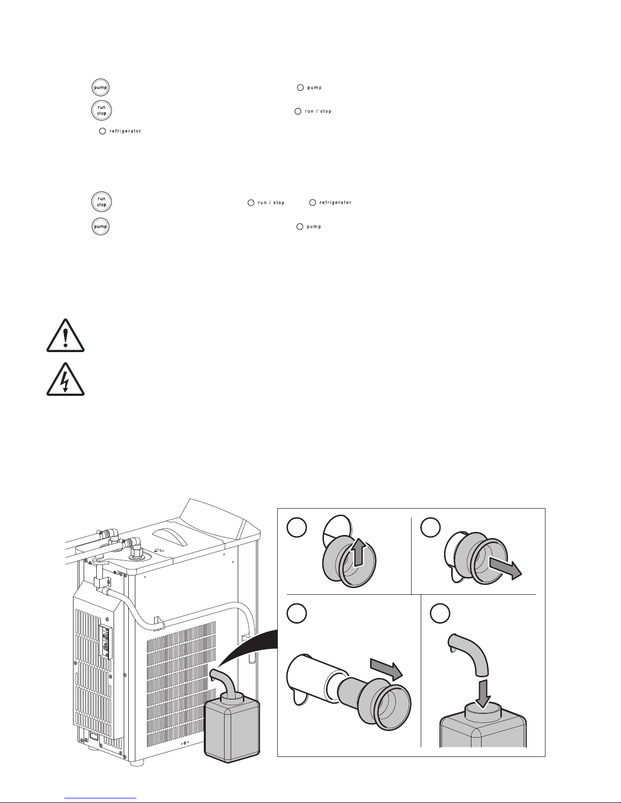
a. Press . The circulation pump will start and the LED will illuminate.
b. Press . Temperature control will start and the LED will illuminate. While the refrigerator is
on the LED will illuminate.
4.5 Stopping operation
NOTE: Before you switch the equipment OFF you MUST stop operation rst.
a. Press . Operation will stop and the and LED's will go off.
b. Press . The circulation pump will stop and the LED will go off.
NOTE: If you are not going to use the equipment for an extended period of time, switch the equipment OFF,
unplug the power lead and disconnect from the mains power supply. Drain water from the circulation bath
and ensure the hoses are empty.
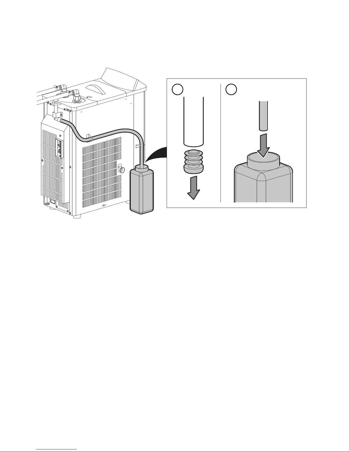
4.6 Drain after use
CAUTION: DO NOT push the drain hose inside the equipment after removing the drain plug as this
could damage the equipment
WARNING: Ensure the equipment is disconnected from the power supply before draining.
NOTE: Before you remove the Drain plug, ensure you have a suitable container to collect the water.#
a. Pull out the Drain hose and Drain plug as shown.
b. Remove Drain plug and allow the system to fully drain.
c. Replace the Drain plug onto the Drain hose and carefully push back into the unit.
i ii
iviii
Page 13
13
4.7 Draining condensation from the tray.
NOTE: Before you remove the Tray drain plug, ensure you have a suitable container to collect the water.
a. Pull out the Tray Drain plug as shown and allow the tray to drain.
b. Replace the Tray Drain plug.
Section 5 - Accessories and Spare Parts
5.1 Optional Accessories
Please visit www.stuart-equipment.com for a full list of available accessories.
5.2 Spare Parts
Please contact your local sales specialist or email [email protected] to enquire about available spares.
i ii
Page 14
14
Section 6 - Maintenance, Servicing and Cleaning
WARNING: Before attempting any maintenance, servicing or cleaning, ensure that the equipment has
been allowed to cool down.
WARNING: Ensure the equipment is disconnected from the power supply before attempting any
maintenance, servicing or cleaning.
6.1 Routine Maintenance
Ensure the external surfaces of the unit are clean and free from dust. The sample area should always be kept clean and
any accidental spillage should be wiped away immediately. To give added protection when not in use, the equipment
should be disconnected from the mains supply. Follow the advice below for cleaning your equipment:
WARNING: This product does not contain bio‐seals as per EN 61010‐1‐2010 and cannot provide any level
of containment in case of a spill or release of toxic, radioactive, or pathogenic micro‐organisms thus
these materials are not recommended to be used in this product.
NOTE: Do not use solvents for cleaning any parts of this equipment.
In Case of Accidental Spillage
WARNING: Do not touch if a spillage/breakage has occurred. Disconnect the power directly at the
power supply source.
If any part of the unit except the circulation bath has been exposed to liquid, it cannot be assumed to meet all
the safety requirements of EN 61010-1-2010 until the drying out process has been fully completed and all safety
requirements are met before the unit is used again.
In Case of Contamination
WARNING: The following procedure is intended as a guide. Should spillage of a toxic or hazardous
uid occur, then additional special precautions may be necessary.
If the equipment has been exposed to contamination, the Responsible Body is responsible for carrying out
appropriate decontamination. If hazardous material has been spilt on or inside the equipment, decontamination
should only be undertaken under the control of the Responsible Body with due recognition of possible hazards.
Before using any cleaning or decontamination method, the Responsible Body should check with the manufacturer
that the proposed method will not damage the equipment. Prior to further use, the Responsible Body shall check
the electrical safety of the unit. Only if all safety requirements are met can the unit be used again.
NOTE: In the event of this equipment or any part of the unit becoming damaged or requiring service, the item(s)
should be returned to the manufacturer for repair accompanied by a decontamination certicate. Copies of the
Certicate are available from the Distributor/Manufacturer.
At the end of its service life, the product must be accompanied by a Decontamination Certicate.
Page 15
15
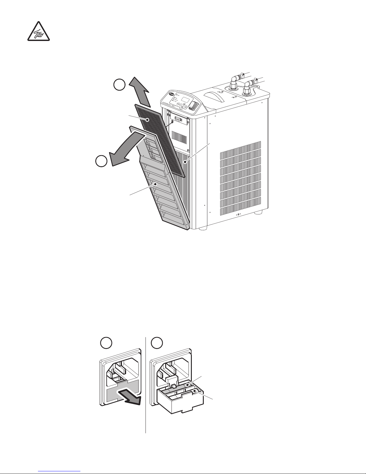
6.2 Cleaning the Air Filter
CAUTION: Take care when removing the Air lter as the Cooling ns have sharp edges.
Pull the Ventilation cover towards you. Remove the Air lter and wash with water and mild detergent. Ensure
the Air lter is dry before re-tting.
6.3 Cleaning Bath Strainer
A strainer is provided to catch foreign objects in the circulation bath. Clean the strainer regularly. Before cleaning
ensure the circulation bath is empty.
6.4 Check Hoses
Check hoses are not kinked or damaged before and after use.
6.5 Fuse Replacement
The mains fuse holder is located at the rear of your product. Refer to section 8.1 for correct fuse type and rating.
Turn your unit off and disconnect it from the power supply. Always replace fuses with the correct type and rating.
i ii
Do not touch the
cooling fin wit h your
bare hands.
It may cut your fingers.
WARNING
Use extreme caut ion
when using
flammable and
ignitable solve nt.
Fire hazard
Touching the
cooling fins ma y
cause burns.
Hot surface
CAUTION
CAUTION
i
ii
Remove and replace fuse
Cooling ns
Spare fuse
Ventilation cover
Air lter
Page 16

16
6.6 Service, Repairs and Support
Any service, repairs or replacement of parts MUST be undertaken by suitably qualied personnel. Only spare parts
supplied or specied by Cole-Parmer or its agents should be used. Fitting of non-approved parts may affect the
performance and safety features designed into the instrument. For a comprehensive list of parts required by service
engineers conducting internal repairs please contact the service department quoting the model and serial number:
Email: [email protected] Tel: +44 (0)1785 810475
For technical support enquiries please contact:
Email: [email protected] Tel: +44 (0)1785 810433
6.7 Warranty
Cole-Parmer Ltd. warrants this instrument to be free from defects in material and workmanship, when used
under normal laboratory conditions, for a period of 3 years. In the event of a justied claim Cole-Parmer will replace
any defective component or replace the unit free of charge. This warranty does NOT apply if damage is caused by
re, accident, misuse, neglect, incorrect adjustment or repair, damage caused by incorrect installation, adaptation,
modication, tting of non-approved parts or repair by unauthorised personnel.
This warranty does not apply to the glassware or vacuum seal.
Cole-Parmer Ltd,
Beacon Road,
Stone,
Staffordshire,
ST15 0SA,
United Kingdom
Email: [email protected]
Tel: +44 (0)1785 810475
Web: www.stuart-equipment.com
Section 7 - Environmental Protection
7.1 Packaging Material
Packaging materials have been carefully selected so they can be sorted for recycling.
7.2 Waste Electrical and Electronic Equipment Directive (WEEE)
At the end of your product and accessories life, it must not be discarded as domestic waste.
Ref: EU Directive 2012/19/EU on Waste Electrical and Electronic Equipment Directive (WEEE). Please
contact your distributor / supplier for further information. For end users outside of the EU consult
applicable regulations.
Page 17

17
Section 8 - Technical Specication
8.1 General Specication
Safety functions
Refrigerator overload relay
Refrigerator protection timer
Fuse
Self diagnostics function
Bath cover PPO
Bath material SUS304
Bath capacity
Approx. 3.2 litres
Maximum. 2.7 litres
Size of bath (internal) W130 x D230 x H115mm
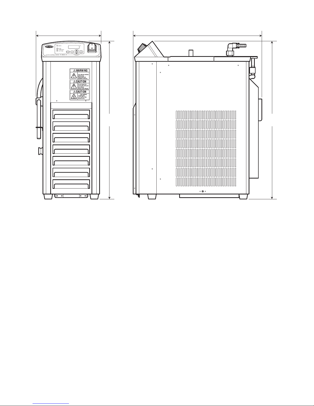
External dimensions W205 x D445 x H545mm
Pump rate 9 litres per minute
Weight 28kg
Display resolution 1°C
Accuracy
± 1°C (30ºC – 0ºC)
± 2°C (-1ºC – -20ºC)
Display Digital Display
Control Sensor PT sensor (100Ω)
Operating ambient temperature
5ºC – 35ºC (indoor use only)
Operating ambient humidity 30 – 75%RH (indoor use only)
Fuse Type
T6.3A 5 x 20 Glass slow blow
Power consumption
450W at 10ºC
350W at 0ºC
310W at -10ºC
Temperature control Refrigeration unit ON - OFF control
Electricity supply 230 V ~ 50Hz
Page 18
18
8.2 Weights and Dimensions
Weight 28kg
Fire hazard
225mm
545
mm
444mm
545
mm
Page 19
19
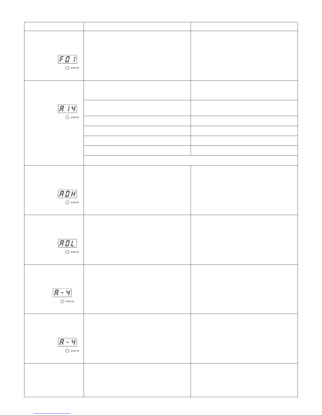
Section 9 - Trouble Shooting
Problem Cause Solution
Temperature sensor
failure alarm.
Equipment has
stopped and
is displayed and
LED is on.
Temperature sensor is disconnected or
broken.
Stop operation and contact a local service
representative.
Refrigeration unit
overload relay alarm.
Equipment has
stopped and
is displayed and
LED is on.
Ambient temperature has exceeded 35ºC.
Set the ambient temperature at 35ºC or
lower*.
The thermal load has exceeded the cooling
capacity.
Keep the thermal load within the specication range*.
Air lter is dusty Clean the air lter*.
Refrigerator fan is not operating. Check the refrigerator fan*.
Low supply voltage Check the power and voltage*.
Refrigerator start up failure Start refrigerator in 10 minutes*.
*Press set to cancel alarm. The overload relay will be ready to use in approx 10 minutes.
Temperature upper
limit alarm.
Equipment has
stopped and
is displayed and
LED is on.
The temperature around the sensor exceeds
the lower limit.
Press Set to cancel alarm. If necessary adjust
temperature upper limit alarm to suit.
Temperature lower
limit alarm.
Equipment has
stopped and
is displayed and
LED is on.
The temperature around the sensor exceeds
the lower limit.
Press Set to cancel alarm. If necessary adjust
temperature lower limit alarm to suit.
Power outage recovery
alarm.
Equipment is still
operating. is
displayed and
LED is on.
Power has been interrupted and then
restored during operation.
Press Set to cancel alarm.
Power outage recovery
alarm.
Equipment has
stopped and
is displayed and
LED is on.
Power has been interrupted and then
restored during operation.
Press Set to cancel alarm. Equipment will
need to be re-started.
Equipment has
stopped, no alarm is
present and there is
nothing on the display
Self-diagnosis has detected a power supply
problem.
Change the power supply and start
equipment again. If problem persists,
Stop operation and contact a local service
representative.
Page 20
20
Nothing is displayed
when power is turned
on.
The inlet fuse has blown.
Replace fuse (see section ??). If problem
persists stop operation and contact a local
service representative.
Mains power is not connected properly. Check power lead is connected properly.
Power is not supplied. Check consumer unit.
Power switch is damaged.
Stop operation and contact a local service
representative.
Temperature controller is damaged.
Refrigeration unit does
not work.
Refrigerator is malfunctioning
Stop operation and contact a local service
representative.
SSR is malfunctioning
Overload relay has been activated.
Reduce thermal load.
Use the equipment where the ambient
temperature is lower than 35ºC.
Protective timer has been activated.
Conrm the refrigerator starts after 10
minutes.
The equipment does
not cool down.
Refrigerator fan is not operating. Check the refrigerator fan.
Gas is leaking.
Stop operation and contact a local service
representative.
Ambient temperature has exceeded 35ºC.
Set the ambient temperature at 35ºC or
lower
The thermal load has exceeded the cooling
capacity.
Keep the thermal load within the specication range.
The equipment is not
cooling down properly.
Water level is low and colling coil is
exposed.
Top up cooling liquid.
An object is blocking exhasut and heat
release.
Check that no vents are covered and the
minimum space required around the object
is observed (see section 3.2).
Water does not circulate.
Bath strainer is blocked. Remove the blockage.
Air is being sucked in.
Remove drain plug (see section 4.6) and
make sure that water can ow, replace
drain plug and press the pump 2 to 3
times to release the air blockage.
Low circulation rate of
cooling liquid.
Hose has collapsed or kinked. Check hose.
Pressure has been lost. Check and restore pressure
Circulation destination is too high. Check installation.
Temperature is set to
7ºC yet the inside of
the bath is frozen.
Restricted circulation due to pressure loss
in hosing etc.
Use antifreeze.
Temperature controller is malfunctioning or
the refrigerator has stopped.
Stop operation and contact a local service
representative.
Page 21

21
Page 22

22
Page 23
23
This product meets the applicable
harmonized standards for radio frequency
interference and may be expected not to
interfere with, or be affected by, other equipment with
similar qualifications. We cannot be sure that other
equipment used in its vicinity will meet these standards
and so we cannot guarantee that interference will not
occur in practice. Where there is a possibility that injury,
damage or loss might occur if equipment malfunctions
due to radio frequency interference, or for general
advice before use, contact the manufacturer.
EU Declaration of Conformity
Product Laboratory Equipment
Manufacturer Cole-Parmer Ltd
Beacon Road
Stone, Staffordshire
ST15 0SA
United Kingdom
File Number P225
Authorised Cole-Parmer
Representative Beacon Road
Stone, Staffordshire
ST15 0SA
United Kingdom
Object of Declaration
Recirculating Coolers
(reference the attached list of catalogue numbers)
The object of the declaration described above is in conformity with the relevant Union Harmonisation Legislation:
References to the relevant harmonised standards used or references to the other technical specications in relation
to which conformity is declared:
Additional Information
Place of Issue
Date of Issue
Authorised Representative
Title
Signature
This declaration of conformity is issued under the sole responsibility of the manufacturer
Signed for and on behalf of the above manufacturer
Low Voltage Directive
EMC Directive
RoHS Directive
2014/35/EU
2014/30/EU
2011/65/EC
IEC/EN 61010-1:2010
Safety requirements for electrical equipment for
measurement, control and laboratory use.
Part 1: General requirements.
Electrical equipment for measurement, control and
laboratory use. EMC requirements.
Part 1: General requirements (Class A).
IEC/EN 61326-1:2013
Year of CE Marking: September 2018
Stone, Staffordshire, UK
4 September 2018
Neil Pomeroy
Technical Director
s.
Declaration of Conformity is also available to view online at www.stuart-equipment.com
Page 24

Cole-Parmer Ltd - UK
Beacon Road,
Stone,
Staffordshire,
ST15 0SA,
United Kingdom
Tel: +44 (0)1785 812121
Email: [email protected]
Web: www.stuart-equipment.com
 Loading...