

Stuart SMP30 Instruction Manual
Melting Point Apparatus
SMP30
Instruction Manual
Version 1.2
English
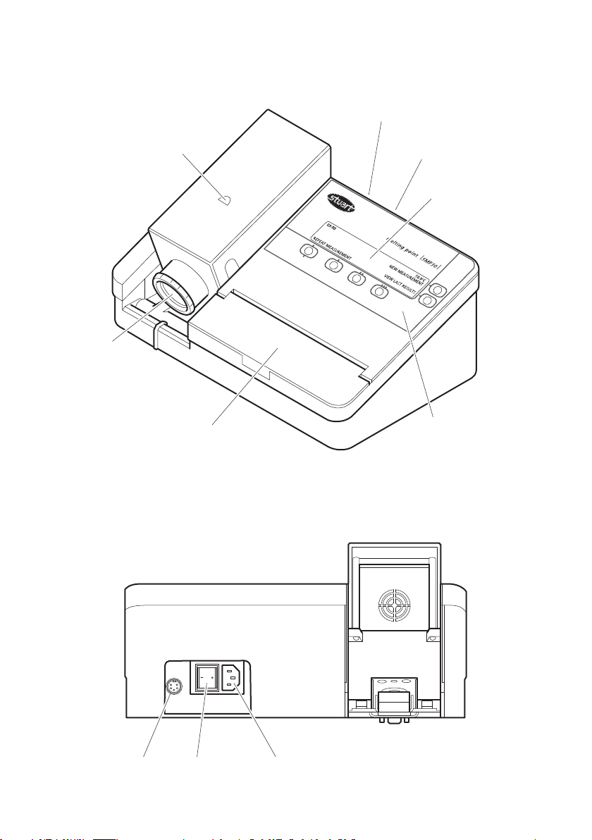
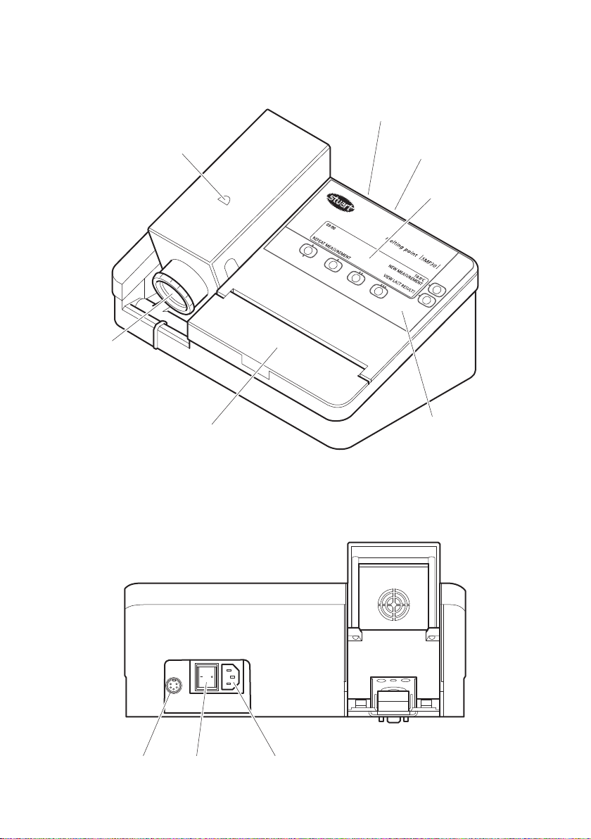
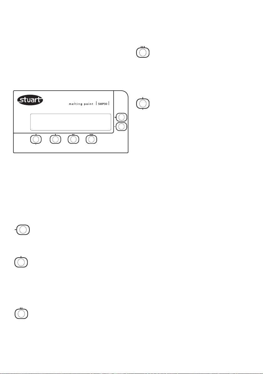
Figure 1 (Front View)
Sample block
Viewer
Power On/Off
(at rear)
Printer output
(at rear)
LCD screen
Capillary storage
Figure 2 (Rear View)
Printer output
Power On/Off
switch
Control key-pad
Mains power
input

Melting Point Apparatus
SMP30
Instructions for use
1. Introduction
Thank you for purchasing this piece of Stuart
equipment. To get the best performance from
the SMP30 please read these instructions
carefully before use. Before discarding the
packaging check that all parts are present and
correct.
For your own safety and that of others
please read and understand the safety
advice given below before using the
equipment.
2. Safety advice before use
If the equipment is not used in the
manner described in this manual and with
accessories other than those recommended
by Cole-Parmer, the protection provided might
be impaired.
This equipment is designed to operate under the
following conditions:
❖ For indoor use only
❖ Use in a well ventilated area
❖ Ambient temperature range +5°C to +40°C
❖ Altitude to 2000m
❖ Relative humidity not exceeding 80%
❖ Mains supply fluctuation not exceeding 10%
❖ Over-voltage category II IEC 60364-4-443
❖ Pollution degree 2
3. General description
The apparatus is designed to measure and record
the temperatures of crystalline samples held
within capillary tubes. Up to three tubes are
accommodated in an illuminated chamber within
the aluminium block. The tubes are viewed
through a magnifying lens on the front of the
unit. All controls are via the membrane keypad.
The temperature range is ambient to 400°C and
the heating rate is variable between 0.5°C per
minute and 10°C per minute. Temperatures and
instrument information are displayed on the LCD
screen. Up to seven temperatures per capillary
tube can be saved and recalled on the screen.
Three methods can be stored for repeated use
and the plateau temperature and heating rate
are fully programmable. When the melt cycle is
started the SMP30 heats up to the
pre-programmed plateau temperature at the
maximum rate before stabilising at the plateau
temperature for 120 seconds. An alarm will
sound to indicate that the SMP30 is ready to
start to heat at the pre-programmed rate. Once
the melt has occurred and the cycle stopped,
cooling is automatic to ambient temperature.
The SMP30 has English, Spanish, French, Italian
and German language options.
Never move or carry the unit when in use or
connected to the mains electricity supply.
The unit should be carried using both hands with
fingers under each side of the frame.
The ventilation slots at the back of the sample
block should not be sealed or obstructed.
1

4. Preparation for use
4.1 Electrical installation
THIS INSTRUMENT MUST BE EARTHED
Before connecting the instrument please read
and understand these instructions and ensure
that the electrical supply corresponds to that
shown on the rating plate. This unit is designed
for use with a supply rated at 115 / 230V,
50-60Hz. The power consumption of the unit is
60W. The unit is fitted with an IEC socket at the
rear of the instrument for connection of the
mains lead.
Caution: Fuses are fitted in both live and
neutral lines.
The unit is supplied with two mains leads fitted
with IEC plugs for connection to the instrument.
One lead has a UK 3 pin plug and the other has
a 2 pin “Shuko” plug for connection to the
mains supply. Choose the lead appropriate for
your electrical installation and discard the other.
Should neither lead be suitable take the lead
with the UK plug and replace the plug with a
suitable alternative. This involves cutting off the
moulded plug, preparing the cable and
connecting to the rewireable plug in accordance
with its instructions.
IT IS IMPORTANT THAT THIS OPERATION
SHOULD ONLY BE UNDERTAKEN BY A
QUALIFIED ELECTRICIAN.
Note: Refer to the equipment’s rating plate to
ensure that the plug and fusing are suitable for
the voltage and wattage stated. The wires in the
mains cable are coloured as follows:
LIVE -BROWN
NEUTRAL -BLUE
EARTH -GREEN/YELLOW
The appropriate mains lead should be connected
to the instrument BEFORE connection to the
mains supply. Should the mains lead require
replacement a cable of 1mm
code H05VV-F connected to an IEC320 plug
should be used.
2
of harmonised
N.B. The UK mains lead is protected by a 10A
fuse mounted in the plug top.
IF IN DOUBT CONSULT A QUALIFIED
ELECTRICIAN
4.2 Connect to the electricity supply DO NOT SWITCH ON
4.3 Place the unit on a firm, level, non-slip
surface ensuring that there is sufficient free
space on all sides without coming into
contact with anything else during use.
4.4 Switch the unit ON at the mains On/Off
switch on the back of the instrument. When
switched ON, the LCD display and the
sample chamber will illuminate.
WARNING: The sample block may
become hot.
5. Operation
5.1 Controls
Figure 1 and 2 show the features for the SMP30.
Mains On/Off: This is a rocker type switch.
Pressing the “I” switches the unit ON. Pressing
the “O” switches the unit OFF.
RS232 Printer Output: The SMP30 can be
connected via the 5 pin mini-DIN socket to a
suitable optional accessory serial printer to
enable a printout of the results to be obtained.
Sample Block: This aluminium block can hold
three capillary sample tubes.
Capillary Storage: A compartment is provided
for the storage of the glass capillaries used in the
melt determinations. This compartment also
incorporates a glass capillary cutter.
Viewer: Comprises a magnifying lens encased
in a plastic eye viewer and allows the “Head Up”
temperature display to be viewed via the eye
viewer.
2
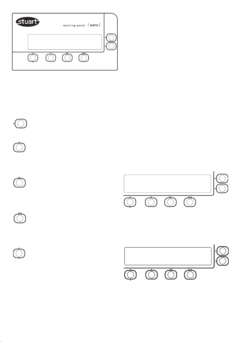
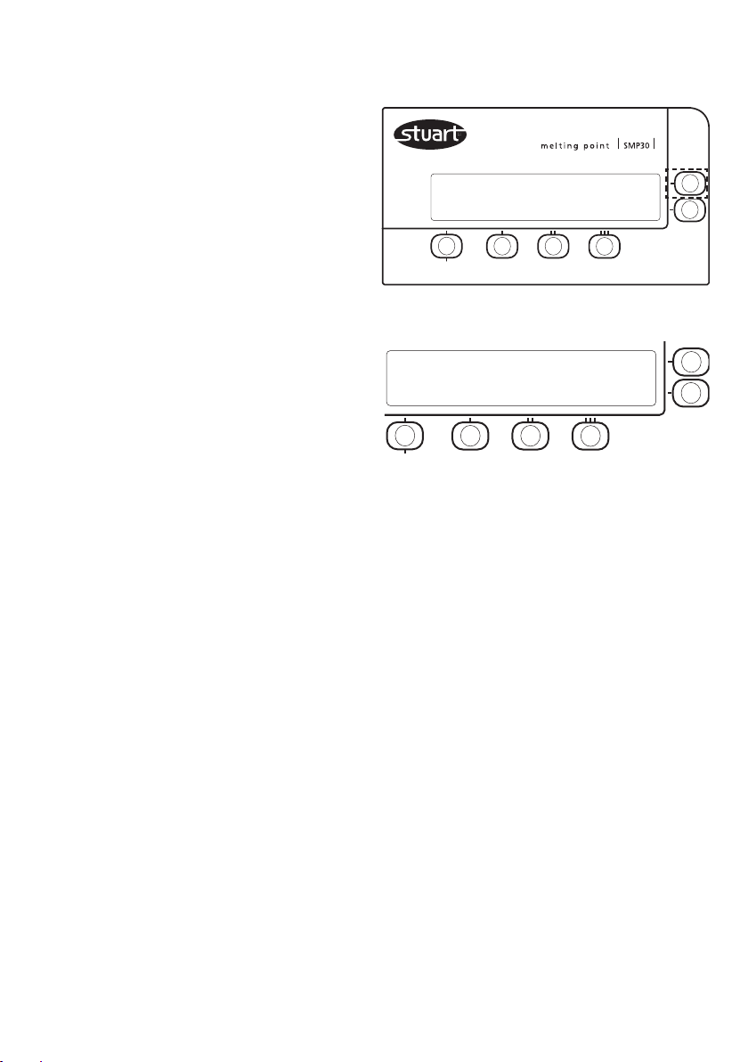
5.2 Main Screen
When the instrument is first switched on the
display will firstly show:
*** STUART SMP30 ***
MELTING POINT APPARATUS
After a short pause, the display will show the
main menu screen and three menu options.
LCD Screen: This display shows programming
information, menu options, stored results, the
current time and current temperature reading.
Keypad: This membrane keypad controls the
SMP30 via the following buttons:-
Upper and lower menu/option keys:
Selects the option displayed next to the key.
I key: During a melt, used to store up to
7 temperature readings for capillary 1. In the
preset method menu it selects the preset method
indicated on the screen above.
II key: During a melt, used to store up to
7 temperature readings for capillary 2. In the
preset method menu it selects the preset method
indicated on the screen above.
III key: During a melt, used to store up
to 7 temperature readings for capillary 3. In the
preset method menu, selects the preset method
indicated on the screen above.
Note: - All menu screens display the time
and current block temperature
The three menu screen options are:
REPEAT MEASUREMENT
- Perform a new melt using the parameters used
during the previous melt
NEW MEASUREMENT
- Perform a new melt
VIEW LAST RESULTS
- View the results from the last melt performed
Note:- Regardless of whether the electrical
supply is maintained, previously recorded
results are stored until a new measurement
is performed.
09:00 50.0°C
REPEAT MEASUREMENT
NEW MEASUREMENT
VIEW LAST RESULTS
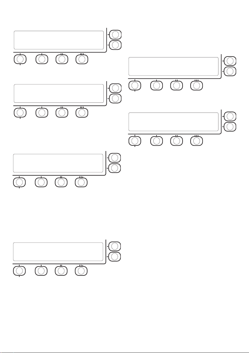
5.3 New Measurement Set-Up
1. Press the upper menu key next to the “NEW
MEASUREMENT” main menu option. The
display will change to:
Enter key: Selects the menu option
displayed above the key or exits/confirms the
current menu/action.
09:00 50.0°C
PRESET PROGRAMME? YES
EXIT
NO
Use the upper menu key next to the “YES”
option to select one of the SMP30’s three
programmable preset methods and proceed to
step 2. Or use the lower menu key next to the
3
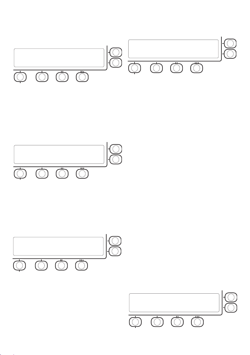
“NO” option to set up a new method and
proceed to step 3.
2. If the “YES” option is pressed the screen will
change to:
09:00 SELECT PROGRAM 50.0°C
PLATEAU 100 150 200
RAMP RATE 1.0 2.0 5.0
EXIT ^ ^ ^
Use the I II or III keys to select the preset method
to be used and proceed to the final screen
shown in 5.
Note:- To change the values in the preset
programmes please see section 5.7
3. If “NO” has been selected the screen will
change to:
09:00 50.0°C
PLATEAU 100°C CHANGE? UP
DOWN
NEXT
Use the upper and lower menu keys next to
“UP” and “DOWN” to adjust the plateau
temperature. Holding these keys down for more
than two seconds will increase the speed at
which the value changes until the key is released.
Use the Enter key to move to the next screen.
4. The next screen displayed is:
09:00 50.0°C
RAMP 1.0°C/min CHANGE? UP
DOWN
NEXT
5. When the method parameters have been
selected using one of the procedures
described in either step 2 or steps 3 to 4, the
following screen is displayed:
09:00 50.0°C
PLATEAU 100°C RAMP 1.0°C/min
READY? START
EXIT
5.4 Performing Melting Point Measurement
1. Place a small amount of sample in a capillary
tube and insert into the aluminium sample
block. Up to three tubes can be
accommodated at any one time.
Note:- Only full length capillary tubes (100mm)
should be used with the SMP30. If capillary
tubes smaller than 60mm in length are used for
melt determinations it may be extremely
difficult to retrieve them from the sample block.
2. Adjust the angle of viewing for maximum
comfort.
3. Set up the instrument with the required
plateau temperature and ramp rate using the
procedure described in “New
Measurement Set-Up”.
4. Use the lower menu key next to “START” to
instruct the instrument to heat/cool to the
plateau temperature. The display changes to
indicate that the instrument is “Heating/
Cooling to plateau” and gives an estimated
time for the instrument to reach the plateau
temperature.
4.1 Once the instrument reaches the plateau
temperature the display changes to
“STABILISING AT PLATEAU 120“. The timer
will then countdown from 120 to 0.
Use the upper and lower menu keys next to
“UP” and “DOWN” to adjust the ramp rate.
Holding these keys down for more than two
seconds will increase the speed at which the
value changes until the key is released. Use the
Enter key to move to the final screen.
4
4.2 Once the countdown reaches 0 the
instrument will make an audible bleep and
the display will change to:
09:00 100.0°C
AT PLATEAU START RAMP
EXIT
5. To begin the melt cycle, use the upper menu

key next to “Start Ramp” to instruct the
instrument to commence the melt program.
6. Once the melt program commences the
display will change to show the
pre-programmed ramping rate and the
temperature displayed on the screen will
increase at the rate selected in the method.
09:00 112.0°C
RAMPING AT 1.0°C/min
DONE
7. Once the melt determination is complete use
the Enter key to select “DONE” to end the
instruments heating program.
5.5 Saving Melt Temperatures
1. During the ramping phase of the melt
determination the I, II and III keys can be used
to record up to seven temperatures for each
capillary.
5.6 Viewing Stored Temperatures
1. Once a melt determination is complete and
the Enter key has been pressed to select
“DONE”, the following screen will be
displayed:
09:00 112.0°C
PRINT RESULTS
VIEW RESULTS
EXIT
2. Use the upper menu key next to “PRINT
RESULTS” to instruct the instrument to print
the stored temperature values on theto the
accessory printer.
Note:- To be able to print the stored
temperature values the accessory printer
SMP30/1 needs to be connected to the
instrument.
3. Use the lower menu key next to “VIEW
RESULTS” to display the results screen as
shown below:
2. An audible bleep will sound each time these
keys are pressed and the recorded
temperature will be displayed on the screen
above the button. Each additional time the
key is pressed another audible bleep will be
heard and the temperature displayed will
update to the last recorded temperature.
09:00 112.0°C
RAMPING AT 1.0°C/min
DONE 108.3°C 109.5°C 109.2°C
Note:-. If an eighth attempt to record a value
is attempted, a longer audible bleep will
sound to indicate that the memory location
is full.
TUBE 1 RESULT 1-2 OF 7 112.0°C
TEMPERATURE 106.2°C 108.2°C UP
RESULT TIME 09:00 09:02 DOWN
DONE
Note:- A maximum of two results will be
displayed on the screen at any one time.
4. Use the upper and lower menu keys next to
“UP” and “DOWN” to scroll through the
recorded results for each tube. Alternatively,
an individual tube’s results can be displayed
using the corresponding I, II and III keys and
once again, by using the upper and lower
menu keys next to “UP” and “DOWN” to
navigate through the recorded results.
5. Once the results have been reviewed use the
Enter key to select “DONE” to return to the
screen in step 1.
5
6. Use the Enter key to select “EXIT”. This will
cause the display to show the current action
of the SMP30; “COOLING TO AMBIENT”.
Once the SMP30 has returned to ambient
temperature, the screen will automatically
display the main menu.
7. Pressing the Enter key again to select “EXIT”
during the cooling program will return the
instrument to the main screen instantly.
Note:- Temperature values remain in the
memory until another melt cycle is initiated
with the “Start Ramp” instruction. The
instrument does not need to be connected
to an electrical supply to maintain the
storage of the recorded results.
5.7 Changing the Instrument Settings
Access to the instrument settings menu is only
available when initially switching on the SMP30.
2. Whilst switching the power on hold the
upper menu key, highlighted in the figure
below.
3. The SMP30 will display the following
screen:
ALARM AT PLATEAU : ON YES
CHANGE? NO
EXIT
The following instrument settings can be
changed by accessing this menu.
Plateau alarm ON/OFF
Head up display ON/OFF
Displayed language selection English,
Spanish,
French, Italian
or German
Time and date adjustment hh:mm and
dd:mm:yyyy
Preset program method settings Default
plateau
temperature
and ramp
rate
1. Ensure that the electrical supply to the
instrument is connected but the instruments
power switch is switched off.
Use the upper and lower menu keys next to
“YES” and “NO” to select whether to edit the
Alarm at Plateau setting. Selecting “YES” will
show a screen with options for that particular
setting and “NO” will move the screen on to
the next parameter.
If “YES” is pressed, the required upper and
lower menu keys should be selected to
determine that setting e.g. Alarm at Plateau
“ON” and “OFF”, using the upper or lower
menu key and then“DONE” should be selected
via the Enter key to move to the next
instrument setting.
For the language option the screen will show
“CHANGE TO SPANISH?”. Selecting the upper
menu key selects Spanish as the language and
the lower menu key moves the display on to
the next language. At any point selecting
“DONE” via the Enter key moves the screen on
to the next instrument setting.
Use the Enter key to select “EXIT” and return
to the instrument's main menu.
6
The preset programme option allows the default
plateau and ramp rate to be set, as follows:
PRESET PROGRAMME YES
CHANGE? NO
EXIT
➮
YES
PROGRAMME 1
PLATEAU 100°C UP
RAMP 1.0°C/min DOWN
CHANGE
Use the upper and lower menu keys next to
“UP” and “DOWN” to select the preset program
number. Use the Enter key to select “CHANGE”
to edit the method.
PROGRAMME 1
PLATEAU 100°C UP
DOWN
NEXT
Use the upper and lower menu keys next to
“UP” and “DOWN” to set the plateau
temperature. Holding these keys down for more
than two seconds will increase the speed at
which the value changes until the key is released.
Pressing the Enter key moves the screen on to
the Ramp rate screen.
PROGRAMME 1
PLATEAU 100°C UP
DOWN
NEXT
Use the upper and lower menu keys next to
“UP” and “DOWN” to set the ramp rate.
Holding these keys down for more than two
seconds will increase the speed at which the
value changes until the key is released. Press the
Enter key to exit back to the instruments main
menu.
5.8 Printing Results Stored Temperature
Values
1. The stored temperature values from the
previous melt determination can be viewed
by pressing the lower menu key next to
“VIEW LAST RESULTS” in the main menu.
TUBE 1 RESULT 1-2 OF 7 112.0°C
TEMPERATURE 106.2°C 109.3°C UP
RESULT TIME 09:00 09:02 DOWN
DONE
2. Press the Enter key to select “DONE” to
display the following screen:
09:00 112.0°C
PRINT RESULTS
VIEW RESULTS
EXIT
3. Press the upper menu key next to “PRINT
RESULTS” to instruct the instrument to print
the stored temperature values.
Note:- A hardcopy of the stored
temperatures can only be produced by using
the optional accessory printer SMP30/1. An
example printout is shown in figure 3.
SMP30
Serial number 00001
Software issue 080716
Calibrated 08 SEPTEMBER 08
DATE 08 SEPTEMBER 08
TIME 9:04
Material.........................
User.............................
Reference........................
Plateau temperature 100...C
Ramp rate 1.0...C/min
Tube 1 Tube 2 Tube 3
106.2...C 106.2...C 106.2...C
9:00 9:00 9:00
108.3...C 108.3...C 108.3...C
9:02 9:02 9:02
108.9...C 108.9...C 108.9...C
9:02 9:02 9:02
109.3...C 109.3...C 109.3...C
9:03 9:03 9:03
109.6...C 109.5...C 109.5...C
9:03 9:03 9:03
109.9...C 109.9...C 109.9...C
9:03 9:03 9:03
Figure 3 (Example Printout using SMP30/1)
7
5.9 Calibration
A customer adjustment to the instruments
calibration can be performed. Please contact the
technical support department for details of the
recalibration procedure.
Email: cptechsupport@coleparmer.com
Tel: +44 (0)1785 810433
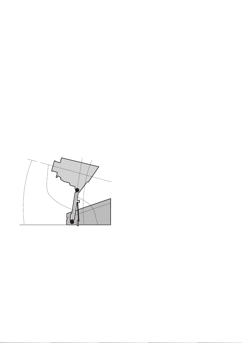
5.10 Adjustment of the Sample Blocks
Viewing Angle and Height.
To suit the individual operators’ requirements the
sample blocks viewing angle and can be
manually adjusted between 0° and 96° in
relation to the height adjustment mechanism.
The height of the viewing block can be manually
raised to 15cm above its resting position in the
unit. Once the position has been manually set,
the sample block will remain in that position
until further adjustments are made by the
operator. Figure 4 shows the maximum angles of
adjustment.
display visible inside the viewing eyepiece. To
adjust the position of the display, please use the
following procedure:-
1. Turn the screw on the left hand side of the
sample block counter-clockwise to allow an
adjustment to be made.
2. Turn the screw on the right hand side of the
sample block clockwise to lower the image in
the viewer or turn it counter-clockwise to
raise the image in the viewer.
3. Turn the screw on the left hand side of the
sample block clockwise to secure the new
position of the “head up” image display.
6. Maintenance & Servicing
WARNING: Ensure the unit is disconnected
from the mains electricity supply before
attempting maintenance or servicing.
This equipment does not require routine
servicing. The only maintenance required is to
clean internal and external surfaces using a
damp cloth and mild detergent solution. Do not
use harsh or abrasive cleaning agents.
14°
Figure 4
(Adjustment angles of the sample block)
Note:- Please take care not to strain the
adjustment mechanism or use excessive
force when changing the position or angle
of the sample block.
5.11 Adjustment of the Sample Blocks
On either side of the sample block there are two
finger adjustable screws that are used to adjust
the position of the “head up” temperature
96°
“Head Up” Display
82°
8
6.1 Repairs and Support
Any repairs or replacement of parts MUST be
undertaken by suitably qualified personnel.
Only spare parts supplied or specified by
Cole-Parmer or its agents should be used.
Fitting of non-approved parts may affect the
performance and safety features designed
into the instrument.
For a comprehensive list of parts required by
service engineers conducting internal repairs
please contact the spares department quoting
the model and serial number:
Email: cpspares@coleparmer.com
Tel. +44 (0)1785 810222

For other technical enquiries please contact the
Service Department at;
Email: cpservice@coleparmer.com
Tel: +44 (0)1785 810475.
6.2 Accessories
The following accessories are available from your
local distributor.
Description Catalogue No
Printer SMP30/1
Capillaries,
open at both ends (pack of 100) SMP1/4
Capillaries,
open at one end (pack of 100) SMP10/1
7. Warranty
Cole-Parmer Ltd. warrants this instrument to be
free from defects in material and workmanship,
when used under normal laboratory conditions,
for a period of 3 years. In the event of a justified
claim Cole-Parmer will replace any defective
component or replace the unit free of charge.
This warranty does NOT apply if damage is
caused by fire, accident, misuse, neglect,
incorrect adjustment or repair, damage caused by
incorrect installation, adaptation, modification,
fitting of non-approved parts or repair by
unauthorised personnel.
In the first instance please contact your
distributor.
Cole-Parmer Ltd.
Beacon Road,
Stone, Staffordshire,
ST15 0SA, United Kingdom
Tel: +44 (0)1785 810475
Email: cpservice@coleparmer.com
Web: www.stuart-equipment.com
9

8. Specification
Overall dimensions
Height: 170mm
Depth: 200mm
Width: 325mm
Weight: 3.6kg
Technical Specifications
Temperature range Ambient to 400°C
Temperature resolution 0.1°C
Ramp rate 0.55°C to 10.0°C/ minute
Cooling Time 350°C to 50°C – 12 minutes
Number of samples Three
Display Alphanumeric, 4 x 40 character LED
Sensor PT1000
Memory storage 7 x temperature readings per sample tube tested
Electrical supply 115V / 230V, 50-60Hz
10
Français
Illustration 1 (Vue avant)
Compartiment
d’échantillons
Lentille
d’observation
Stockage des
capillaires
Interrupteur
Marche/Arrêt
(à l’arrière)
Prise d’imprimante
(à l’arrière)
Écran LCD
Clavier de
commande
Illustration 2 (Vue arrière)
Prise d’imprimante
Interrupteur
Marche/Arrêt
Prise secteur
11

Appareil de mesure
du point de fusion
SMP30
Instructions d’utilisation
1. Introduction
Nous vous remercions d’avoir fait l’acquisition de
cet équipement Stuart. Pour profiter au mieux
des performances du SMP30, lisez attentivement
ces instructions avant toute utilisation. Avant de
jeter l’emballage, vérifiez que tous les éléments
sont présents et en bon état.
Pour votre propre sécurité ainsi que pour celle
d’autrui, assurez-vous de lire et de parfaitement
comprendre les consignes de sécurité décrites
ci-dessous avant d’utiliser l’appareil.
2. Consignes de sécurité
Si l’appareil n’est pas utilisé conformément
aux directives détaillées dans ce manuel ou
avec des accessoires différents de ceux
recommandés par Cole-Parmer, la protection
fournie risque d’être inefficace.
Cet appareil est conçu pour fonctionner dans les
conditions suivantes :
❖ Utilisation à l’intérieur uniquement
❖ Utilisation dans un lieu correctement ventilé
❖ Température ambiante de +5°C à +40°C
❖ Altitude maximale de 2000m
❖ Taux d’humidité relative de 80% au plus
❖ Fluctuations de l’alimentation secteur ne
dépassant pas 10%
❖ Surtension de catégorie II IEC 60364-4-443
❖ Degré de pollution2
3. Description générale
L’appareil est conçu pour mesurer et enregistrer
les températures des prélèvements cristallins dans
les tubes capillaires. Jusqu’à trois tubes sont
installés dans la chambre illuminée à l’intérieur du
bloc en aluminium. Le tubes sont visualisés à
travers une loupe située à l’avant de l’appareil.
Toutes les fonctions sont contrôlées à l’aide du
clavier à membrane.
La plage de températures va de la température
ambiante à 400°C et la montée en température
est réglable de 0,5°C par minute à 10°C par
minute. Les températures et les informations sur
l’appareil sont affichées sur l’écran LCD. Il est
possible d’enregistrer jusqu’à sept températures
par tube capillaire et de les consulter sur l’écran.
Trois méthodes peuvent être stockées en vue de
les réutiliser et la température de plateau ainsi
que la montée en température sont entièrement
programmables. Une fois le cycle de fusion lancé,
le SMP30 chauffe jusqu’à la température de
plateau préprogrammée à la vitesse maximale
avant de se stabiliser à la température de plateau
pendant 120s. Une alarme retentit pour indiquer
que le SMP30 est prêt à chauffer au taux
préprogrammé. Après la fusion et l’arrêt du cycle,
le refroidissement se fait automatiquement à la
température ambiante.
Le SMP30 est disponible en anglais, en espagnol,
en français, en italien et en allemand.
Ne jamais déplacer ou porter l’appareil lorsqu’il
est en fonctionnement ou connecté à
l’alimentation secteur.
Porter l’appareil en plaçant les mains sous le
châssis, de part et d’autre de celui-ci.
Les fentes de ventilation situées à l’arrière du bloc
d’échantillons ne doivent pas être obstruées.
12

4. Préparation à
l’utilisation
4.1 Installation électrique
CET APPAREIL DOIT ÊTRE MIS À LA TERRE.
Le cordon d’alimentation approprié doit être
connecté à l’appareil AVANT de le brancher sur
une prise secteur. Si le cordon d’alimentation
doit être remplacé, utilisez un câble d’1mm2 de
type H05VV-F harmonisé, connecté à une fiche
IEC320.
Avant de connecter l’appareil, assurez-vous de
lire et de parfaitement comprendre ces
instructions. Vérifiez que l’alimentation secteur
correspond aux caractéristiques indiquées sur la
plaque signalétique. Cet appareil est conçu pour
une alimentation de 115/230V, 50-60Hz. Sa
consommation électrique est de 60W. L’appareil
est équipé d’une prise IEC sur sa face arrière,
pour la connexion du cordon d’alimentation.
Attention: Des fusibles sont installés sur les
lignes de phase et de neutre.
Cet appareil est fourni avec deux cordons
d’alimentation équipés de fiches IEC. L’un de ces
cordons est équipé d’une fiche britannique à
3broches et l’autre est équipé d’une fiche
«Shuko» à 2broches. Choisissez le cordon
d’alimentation adapté à votre installation
électrique et mettez l’autre de côté. Si aucun des
cordons ne convient, utilisez le cordon équipé
d’une fiche britannique après avoir remplacé
celle-ci par une fiche appropriée. Pour ce faire,
coupez le cordon du côté de la fiche moulée,
préparez les fils et connectez-les à une fiche
démontable, conformément aux instructions
fournies avec cette dernière.
IL EST IMPORTANT QUE CETTE OPÉRATION
SOIT RÉALISÉE PAR UN ÉLECTRICIEN
QUALIFIÉ UNIQUEMENT.
Remarque: Reportez-vous à la plaque
signalétique de l’appareil afin de vous assurer
que la fiche et les fusibles sont adaptés à la
tension et à la puissance mentionnées. Les
couleurs des fils du cordon d’alimentation sont
les suivantes:
PHASE -MARRON
NEUTRE -BLEU
TERRE -VERT/JAUNE
Remarque: Le cordon d’alimentation équipé
d’une fiche britannique est protégé par un
fusible de 10A monté dans la partie supérieure
de la fiche.
EN CAS DE DOUTE, CONSULTEZ UN
ÉLECTRICIEN QUALIFIÉ.
4.2 Connectez l’appareil à l’alimentation
secteur. NE LE METTEZ PAS SOUS TENSION.
4.3 Placez l’appareil sur une surface stable, à
niveau et non glissante en veillant à laisser
un espace suffisant de chaque côté afin
qu’il n’entre en contact avec aucun élément
lors de son utilisation.
4.4 Mettez l’appareil sous tension (ON) en
appuyant sur l’interrupteur Marche/Arrêt
situé à l’arrière de l’appareil. Lorsqu’il est
allumé, l’écran LCD et la chambre de
prélèvement s’illuminent.
AVERTISSEMENT:
Le bloc d’échantillons peut chauffer.
5. Utilisation
5.1 Fonctions
Les illustrations 1 et 2 présentent les fonctions
du SMP30.
Interrupteur Marche/Arrêt: Il s’agit d’un
interrupteur à bascule. Si vous appuyez sur la
position «I», vous allumez l’appareil. Si vous
appuyez sur la position «O», vous éteignez
l’appareil.
Prise d’imprimante: Il est possible de
raccorder le SMP30 à une imprimante
optionnelle via la prise DIN 5broches afin
d’imprimer les résultats.
13
Bloc d’échantillons: Le bloc en aluminium peut
contenir jusqu’à trois tubes d’échantillons
capillaires.
Stockage des capillaires: Compartiment
fourni pour le stockage des capillaires en verre
utilisés pour déterminer le point de fusion.
Visionneuse: Comprend une loupe intégrée
dans une visionneuse en plastique qui permet de
voir l’affichage tête haute de la température.
température pour le capillaire2. Lorsque vous
êtes dans le menu de méthode présélectionnée,
elle permet de choisir la méthode
présélectionnée indiquée sur l’écran ci-dessus.
ToucheIII: Lors d’une fusion, touche
utilisée pour stocker jusqu’à 7mesures de
température pour le capillaire3. Lorsque vous
êtes dans le menu de méthode présélectionnée,
elle permet de choisir la méthode
présélectionnée indiquée sur l’écran ci-dessus.
Touche d’entrée: Permet de sélectionner
l’option de menu affichée au-dessus de la touche
ou de quitter/confirmer le menu/l’action
sélectionnée.
5.2 Écran principal
Écran LCD: Cet écran présente des informations
de programmation, des options de menu, des
résultats stockés, l’heure actuelle et la mesure de
température actuelle.
Clavier: Ce clavier à membrane permet de
contrôler l’appareil SMP30 à l’aide des boutons
suivants:
Touches de menu/d’option du haut/bas:
Permet de sélectionner l’option affichée en
regard de la touche.
Touche I: Lors d’une fusion, touche
utilisée pour stocker jusqu’à 7mesures de
température pour le capillaire1. Lorsque vous
êtes dans le menu de méthode présélectionnée,
elle permet de choisir la méthode
présélectionnée indiquée sur l’écran ci-dessus.
ToucheII: Lors d’une fusion, touche
utilisée pour stocker jusqu’à 7mesures de
À la première mise sous tension de l’appareil,
l’écran affiche:
*** STUART SMP30 ***
APPAREIL DE MESURE DU POINT DE FUSION
Après une courte pause, l’écran principal et trois
options de menu apparaissent.
Remarque: - Tous les écrans de menu
affichent l’heure et la température actuelle
du bloc.
Les trois options de menu sont les suivantes:
RÉPÉTER LA MESURE:
- Permet de réaliser une nouvelle fusion à l’aide
des réglages utilisés lors de la fusion précédente.
NOUVELLE MESURE
- Permet de réaliser une nouvelle fusion.
AFFICHER LES DERNIERS RÉSULTATS:
- Permet d’afficher les résultats de la dernière
fusion réalisée.
Remarque: Même si l’alimentation
électrique est coupée, les résultats
précédemment enregistrés sont stockés
jusqu’à ce qu’une nouvelle mesure soit
effectuée.
14

09:00 50.0°C
AFFICHER LES DERNIERS RESULTATS
REPETER LA MESURE
NOUVELLE MESURE
3. Si «NON» a été sélectionné, l’affichage
suivant apparaît:
09:00 50.0°C
PLATEAU 100°C CHANGE? HAUT
BAS
SUIVENT
5.3 Configuration d’une nouvelle mesure
1. Appuyez sur la touche de menu du haut en
regard de l’option du menu principal
«NOUVELLE MESURE». L’affichage suivant
apparaît.
09:00 50.0°C
PROGRAMME PREDEFINI? OUI
SORTIE
NON
Utilisez la touche de menu du haut en regard de
l’option «OUI» pour sélectionner l’une des trois
méthodes prédéfinies programmable du SMP30
et passer à l’étape2. Ou utilisez la touche de
menu du bas en regard de l’option «NON» pour
configurer une nouvelle méthode et passer à
l’étape3.
2. Si l’option «OUI» est sélectionnée,
l’affichage suivant apparaît:
09:00 CHOISIR PROGRAM 50.0°C
PLATEAU 100 150 200
TAUX D'AUGMENTATION 1.0 2.0 5.0
SORTIE ^ ^ ^
Réglez la température de plateau à l’aide des
touches de menu du haut et du bas en regard de
«HAUT» et «BAS». Maintenir ces touches
enfoncées pendant plus de deux secondes
augmente la vitesse à laquelle la valeur change
jusqu’à ce que la touche soit relâchée. Utilisez la
touche Entrée pour passer à l’écran suivant.
4. Cet écran se présente comme suit:
09:00 50.0°C
AUGMENTATION 1.0°C/min CHANGE? HAUT
BAS
SUIVENT
Réglez le taux de rampe à l’aide des touches de
menu du haut et du bas en regard de «HAUT»
et «BAS». Maintenir ces touches enfoncées
pendant plus de deux secondes augmente la
vitesse à laquelle la valeur change jusqu’à ce que
la touche soit relâchée. Utilisez la touche Entrée
pour passer à l’écran final.
5. Une fois les paramètres de la méthode
sélectionnés à l’aide de l’une des procédures
décrites aux étapes2, 3 ou4, l’écran suivant
apparaît:
Utilisez les touches I, II ou III pour sélectionner la
méthode prédéfinie à utiliser et passez à l’écran
final illustré à l’étape5.
Remarque: Pour modifier les valeurs des
programmes prédéfinis, reportez-vous à la
section5.7.
09:00 50.0°C
PLATEAU 100°C AUGMENTATION 1.0°C/min
PRET? DEMARRE
SORTIE
15

5.4 Mesure du point de fusion
1. Placez une petite quantité de l’échantillon
dans le tube capillaire et insérez-le dans le
bloc d’échantillons en aluminium. Vous
pouvez y installer jusqu’à trois tubes à la fois.
Remarque: Utilisez uniquement des tubes
capillaires longs (100mm) avec le SMP30. Si
vous utilisez des tubes capillaires d’une
longueur inférieure à 60mm pour
déterminer le point de fusion, il peut
s’avérer extrêmement difficile de les extraire
du bloc d’échantillons.
2. Ajustez l’angle de vision pour un confort
maximal.
3. Configurez l’appareil avec la température de
plateau et le taux de rampe requis selon la
procédure décrite dans la section
«Configuration d’une nouvelle
mesure».
«DÉMARRER LA RAMPE» pour lancer le
programme de fusion.
6. Une fois le programme de fusion commencé,
l’affichage change pour faire apparaître le
taux de rampe préprogrammé et la
température affichée sur l’écran augmente au
taux sélectionné dans la méthode.
09:00 112.0°C
RAMPE 1.0°C/min
TERMINE
7. Une fois le point de fusion déterminé, utilisez
la touche Entrée pour sélectionner
«TERMINÉ» à la fin du programme de
chauffage de l’appareil.
5.5 Enregistrement des températures de
fusion
4. Utilisez la touche de menu du bas en regard
de «DÉMARRER» pour indiquer à
l’instrument de chauffer/refroidir à la
température de plateau. L’affichage change
pour indiquer que l’appareil est en cours de
chauffage/refroidissement à la température
de plateau et fournir une estimation du
temps pour atteindre cette température.
4.1 Une fois que l’appareil a atteint la
température de plateau, l’affichage
«STABILISATION AU PLATEAU 120»
apparaît. Le minuteur procède alors à un
décompte de 120 à 0.
4.2 Une fois le décompte terminé, l’appareil
émet un bip et l’affichage suivant apparaît:
09:00 100.0°C
AU PLATEAU DEMARRER LA RAMPE
SORTIE
5. Pour commencer le cycle de fusion, utilisez
la touche de menu du haut en regard de
1. Lors de la phase de rampe de détermination
du point de fusion, les touches I, II et III
permettent d’enregistrer jusqu’à sept
températures par capillaire.
2. Un bip retentit chaque fois que ces touches
sont actionnées et la température enregistrée
s’affiche sur l’écran au-dessus du bouton.
Chaque fois que vous appuyez sur la touche,
un autre bip retentit et la température
affichée est mise à jour pour refléter la
dernière température enregistrée.
09:00 112.0°C
RAMPE 1.0°C/min
TERMINE 108.3°C 109.5°C 109.2°C
Remarque: Si vous essayez d’enregistrer une
huitième valeur, un bip plus long retentit
pour indiquer la mémoire est pleine.
5.6 Affichage des températures enregistrées
16
 Loading...