

Stuart SI500, SI600, SI600C Instruction Manual
Shaking Incubators
SI500, SI600, SI600C
Instruction Manual
Version 2.3
start/stop mode
rpm
time
on/off
press
to
start
temperature ºC
on/off
o
rbita
li n
c
u
bato
r
S
I
5
00
orbital incubator
SI600
on/off
press to set
temperature ºC
on/off
time
rpm
start/stop
mode
start/stop mode
rpm
time
on/off
press
to
start
temperature ºC
on/off
o
rb
ita
l in
c
u
bato
r
S
I
5
00
start/stop mode
rpm
time
on/off
press
to
start
temperature ºC
on/off
o
rb
ita
l in
c
u
b
a
to
r
S
I
5
00
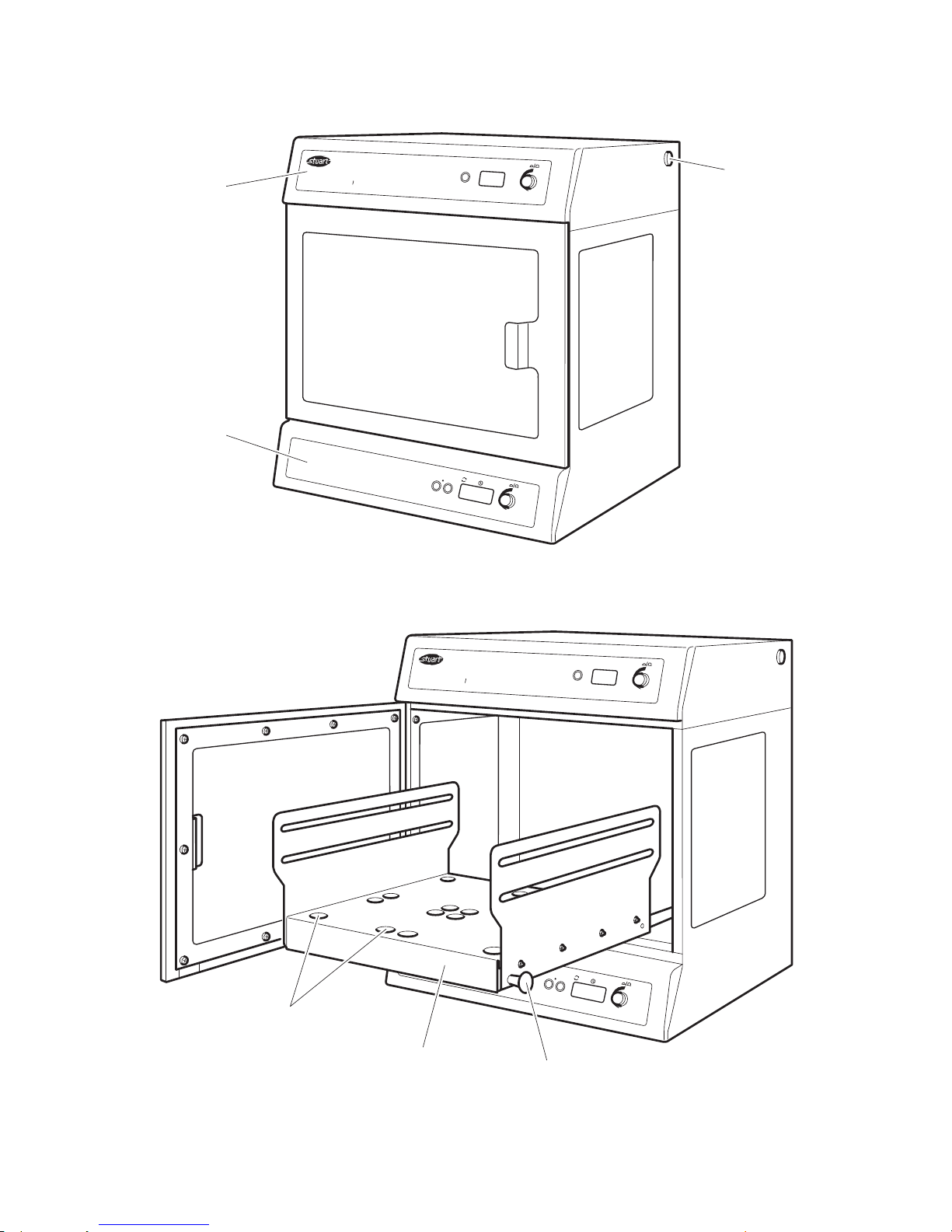
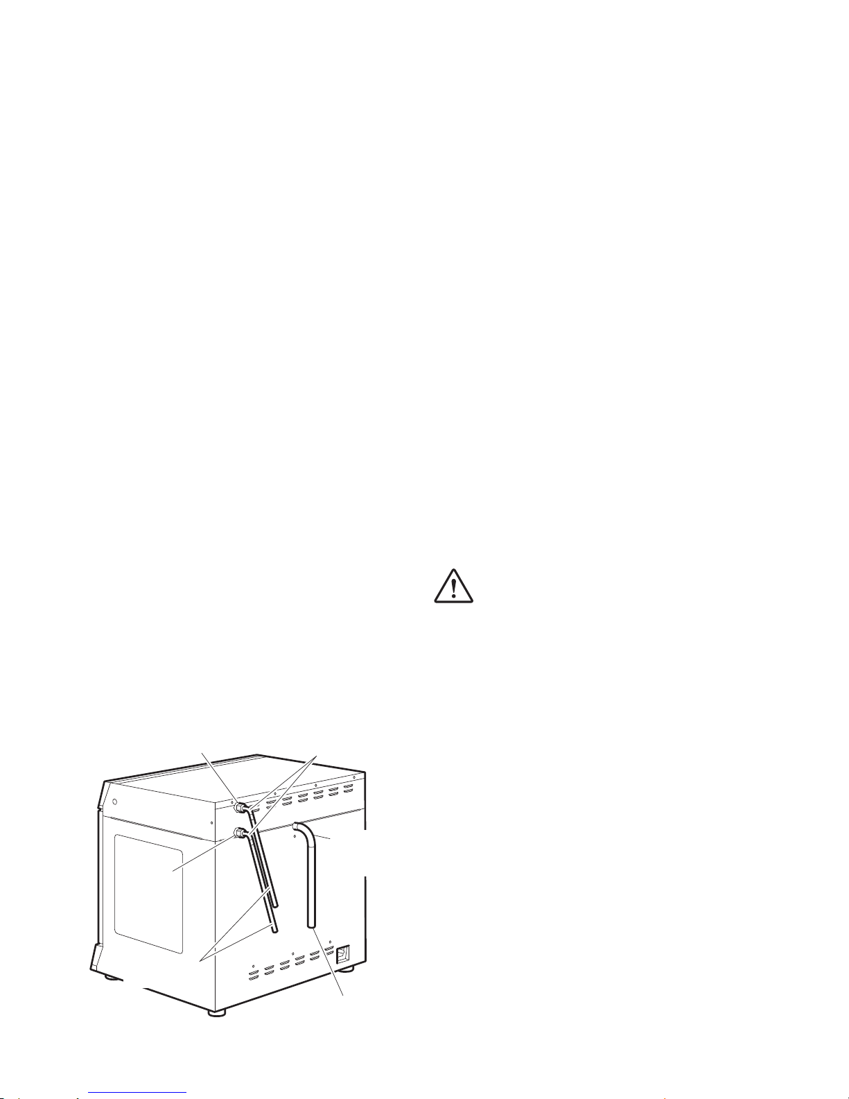
Temperature
control panel
Speed control
panel
USB connector
Locating holes for
tube accessory racks
Retractable
platform
Retractable
platform
release knob
English

1
SHAKING INCUBATORS
SI500, SI600 and SI600C
Instructions for use
1. Introduction
Thank you for purchasing this piece of Stuart
equipment. To get the best performance from
this equipment please read these instructions
carefully before use. Before discarding the
packaging check that all parts are present and
correct.
Item number Description
HH179(S) UK mains lead with plug
HH180(S) EU mains lead with plug
SI500-MAN Instruction manual
I/FCALUSB USB cable
RSSL1 or SI600/1 Securing bars (4)
7001096 Guarantee card
SI600-214 Foot brackets (2) and
screws (4) for SI600 and
SI600C
SI600C only:
SI600C-232 Washer (2)
SI600C-233 90° connectors (2)
SI600C-240 Condensate tubing (2)
SI600C-241 Coolant tubing (2)
SBS4074 Jubilee clip (1)
700198 Jubilee clips (4)
For your own safety and that of others
please read and understand the safety
advice given below before using the
equipment.
2. Safety advice before use
If the equipment is not used in the manner
described in this manual and with
accessories other than those recommended
by Cole-Parmer, the protection provided
might be impaired.
This equipment is designed to operate under the
following conditions:
❖ For indoor use only
❖ Use in a well ventilated area
❖ Ambient temperature range +5ºC to +40ºC
❖ Altitude to 2000m
❖ Relative humidity not exceeding 80%
❖ Mains supply fluctuation not exceeding 10%
❖ Over-voltage category II IEC60364-4-443
❖ Pollution degree 2
Operational warnings and conditions:
CAUTION: HEAVY OBJECT. DO NOT
ATTEMPT TO LIFT OR CARRY THE UNIT
ALONE.
❖ Use with a minimum distance all around of
200mm (100mm at the rear) from walls or
other items.
❖ Not to be used to heat or mix materials which
could result in liberation of gases, or cause
explosions or implosions.
❖ Not to be used or placed in areas known to
be hazardous.
❖ Never move or carry the unit when in use or
connected to the mains electricity supply.
❖ When lifting or moving the unit, always lift
from the base.
❖ Do not use in a hazardous atmosphere or
with hazardous materials.
❖ Ensure that the load is balanced.
❖ Do not attempt to stop movement by hand.
❖ Do not lean on the open door of the SI600 or
SI600C as this could cause the unit to tilt,
particularly when the platform is extended.
Furthermore, do not leave the incubator
unattended with the door open.
❖ Fitting of feet brackets to the SI600 and
SI600C is required prior to use (see 4.4).
❖ In the case of mains interruption, the unit will
not restart on restoration of the electricity
supply. In the case of mechanical interruption,
(e.g. motor stall), the unit will continue
operating on removal of interruption.
❖ Mechanical energy can lead to breakage of
glass vessels. Use with care.
USE CAUTION WHEN REMOVING
VESSELS FROM THE INCUBATOR AS
PARTS MAY BE HOT.

3. General description
The Stuart SI500, SI600 and SI600C orbital
incubators are ideal for mixing and aerating
various biological samples under accurate
temperature controlled conditions. The rotating
platform has a digital speed setting providing a
smooth, uniform circular motion with an orbit of
16mm. The speed range is 30 to 300rpm. There
is also an adjustable digital countdown timer
that automatically stops after the set time (1
second steps to 1h, 1 minute steps to 24h or 1h
steps to 9 days). The shaking platform has a
drawer mechanism for easy access to the
incubation vessels. The temperature is controlled
by a simple “press to set” system in 0.1ºC
intervals from ambient +5ºC to 60ºC.
The model SI600C has the additional option of
connecting to a recirculating chiller unit allowing
for applications where sub-ambient temperature
conditions (ambient -15°C, minimum 5°C) are
required.
The incubators come fitted with a fully
adjustable cradle system to accommodate a wide
range of flasks and bottles. Optional accessories
include racks to accommodate 1.5ml, 15ml and
50ml tubes.
4. Preparation for use
4.1 Electrical installation
THIS INSTRUMENT MUST BE EARTHED
Before connecting the instrument please read
and understand these instructions and ensure
that the line supply corresponds to that shown
on the rating plate. The instrument is designed
for use on 230V 50Hz. The power consumption
of the unit is 300W for the SI500 and 500W for
the SI600 and SI600C. Ensure that a mains
supply lead with the correct ratings for the
product is used. The instrument is fitted with an
IEC socket at the rear of the instrument for
connection of the mains lead. The mains supply
lead is the means of disconnection for the
instrument.
Caution: Fuses are fitted in both live and
neutral lines.
2
Fuses:
230V - 3.15A anti surge fuse. For all other
voltages always replace with an equivalent fuse
type and rating as those being removed,
alternatively see rating plate for fuse type and
rating.
This unit is supplied with two mains leads fitted
with IEC plugs for connection to the instrument.
One lead has a U.K. 3 pin plug and the other has
a 2-pin “Schuko” plug for connection to the
mains. Choose the lead appropriate for your
electrical installation and discard the other.
Should neither lead be suitable, take the lead
with the U.K. plug and replace the plug with a
suitable alternative. This involves cutting off the
moulded plug, preparing the cable and
connecting to the rewireable plug in accordance
with its instructions.
IT IS IMPORTANT THAT THIS OPERATION
SHOULD ONLY BE UNDERTAKEN BY A
QUALIFIED ELECTRICIAN
NOTE: Refer to the equipment’s rating plate to
ensure that the plug and fusing are suitable for
the voltage and wattage stated. The wires in the
mains cable are coloured as follows:
LIVE - BROWN
NEUTRAL - BLUE
EARTH - GREEN/YELLOW
The appropriate mains lead should be connected
to the instrument BEFORE connection to the
mains supply. Should the mains lead need
replacement a cable of 1mm2 of harmonised
code H05VV-F connected to an IEC320 plug
should be used. N.B. the U.K. mains lead is
protected by a 10A fuse mounted in the plug
top.
IF IN DOUBT CONSULT A QUALIFIED
ELECTRICIAN
4.2 Positioning
Place the unit on a strong, sturdy, level, non-slip
surface ensuring that there is sufficient free
space on all sides without coming into contact
with anything during use. Allow at least 100mm
at the rear for easy access to the mains power
supply lead and 200mm at each side of the
instrument.
3
WARNING:
❖ Do not use flammable coolants.
❖ Consult the chiller manual to ensure a
compatible fluid is used.
❖ The fluid must be compatible with the
incubator’s wetted parts which are
brass, copper, EPDM rubber and nickel.
When using coolant below 0°C, there is the
potential for condensate to form on the tubing.
This can be reduced by insulating the tubing.
Ensure all tubing is kept free of kinks and
restrictions and is held tidily in place using tie
wraps if necessary. Check for leaks by starting up
the chiller pump before finally fixing the SI600C
in position on the bench.
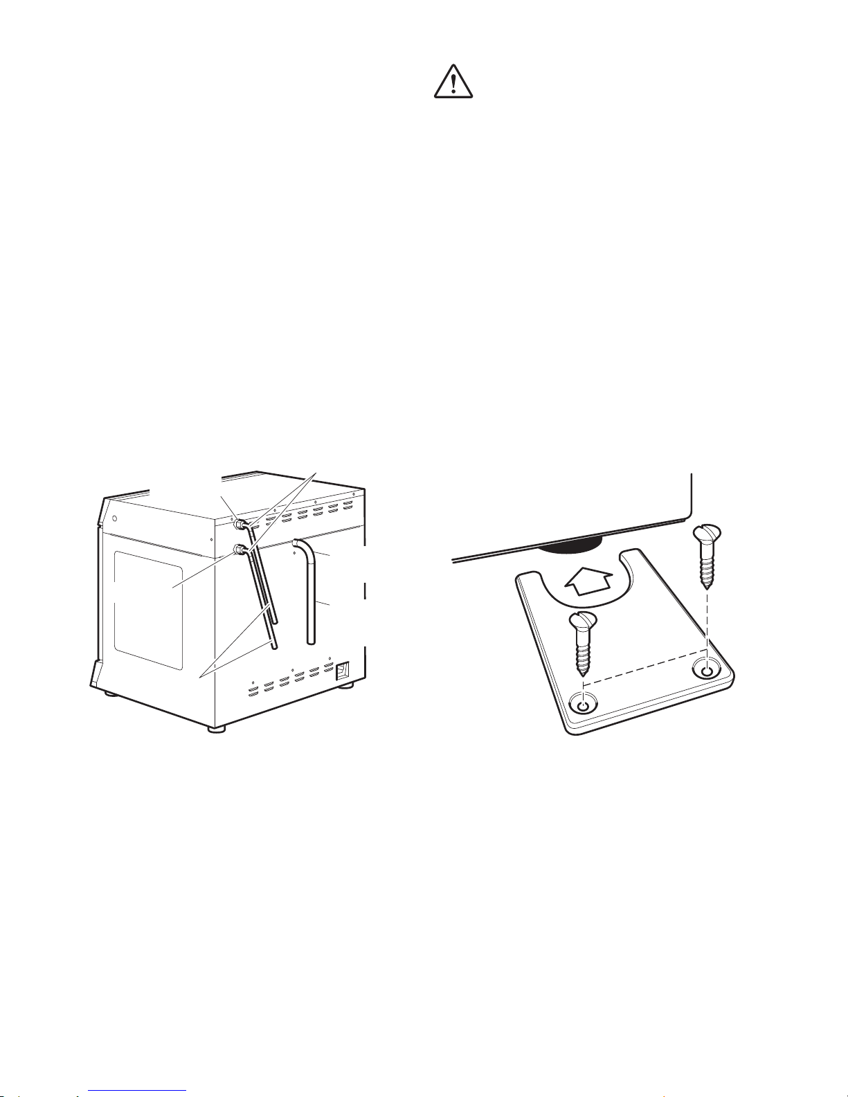
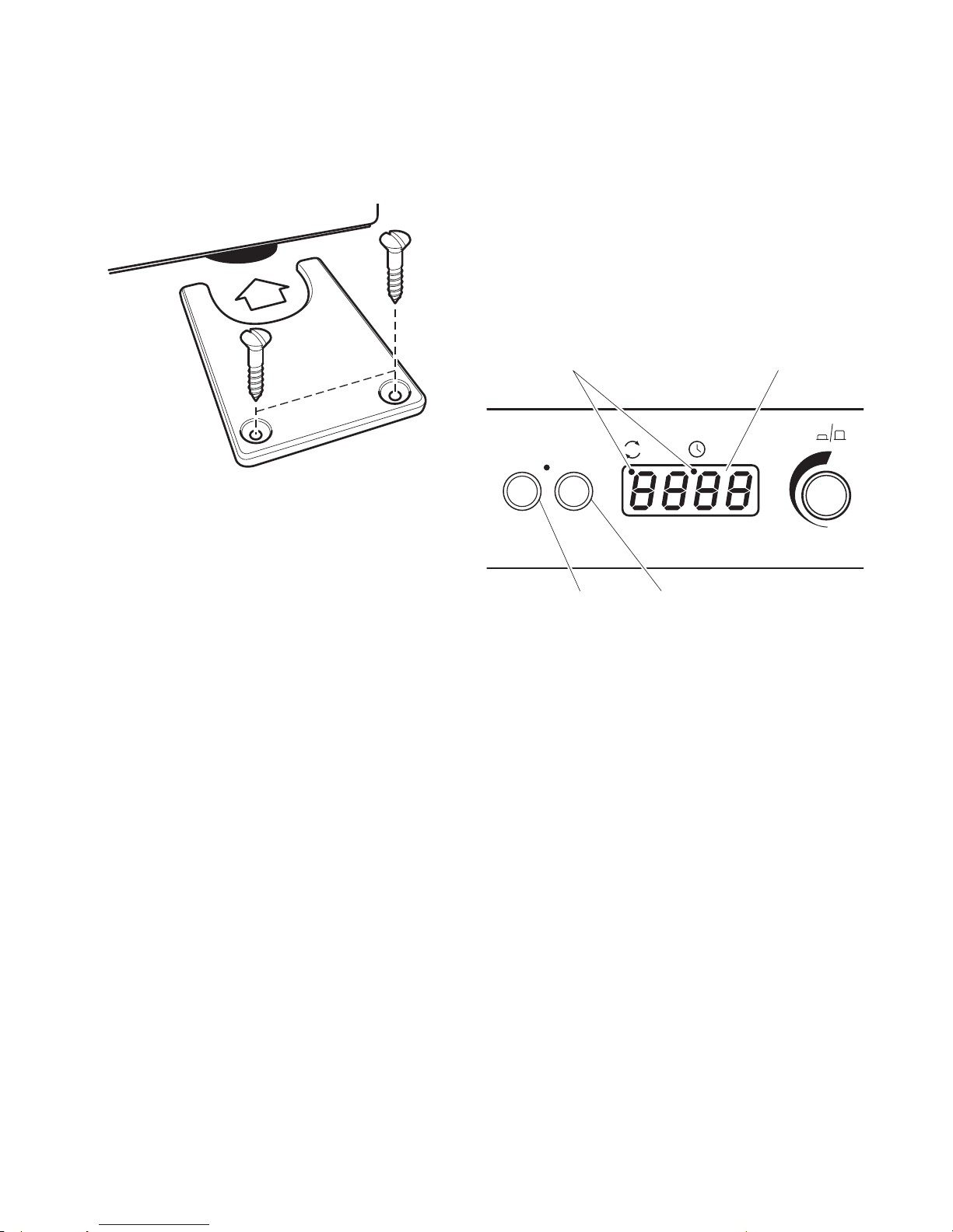
4.4 Fixing feet brackets (SI600 and SI600C)
To prevent the unit from vibrating or moving
during use, the SI600 and SI600C must be
secured to the bench top using feet brackets.
Two feet brackets are provided for securing the
rear feet.
1
2
Ensure the unit is positioned correctly. From the
sides of the unit, slide the feet brackets around
each of the rear feet (1). Secure in place by fixing
with two No.8 x 20mm screws (2).
Connect to the electricity supply - DO NOT
SWITCH ON.
4.4 Loading
Caution: keep loose items clear of the door
before opening.
Open the door. Pull the two black sprung release
knobs either side of the cradle outwards towards
the sides of the incubator and draw the cradle
platform out of the incubator towards you.
4.3 Connecting the SI600C to a recirculating
chiller
In order to incubate at below ambient conditions,
the SI600C must be connected to a recirculating
chiller unit. Ensure that the chiller unit is situated
on a solid surface and does not vibrate when the
incubator is operating at maximum rpm. Connect
the condensate tubing to the condensate outlet
pipe and the other end to a waste collection
container positioned lower than the condensate
outlet pipe. Ensure the condensate collection
container can hold a liquid volume at least as
great as the chiller coolant volume.
Attach the 90° connectors supplied to the two
connectors on the rear of the unit labelled INLET
and OUTLET. Connect the 1.5m lengths of 8mm
I.D. EPDM tubing to the connectors and secure
with jubilee clips. Connect the other ends of the
connectors to the ports of the chiller unit
ensuring there are no kinks in the tubing to
restrict flow; do not over-tighten.
Optimum performance will be obtained with the
connection tubing as short as possible. Observe
the specification of the chiller for acceptable
tubing lengths and maximum head height. Place
the chiller in a position which is safe in order to
prevent accidental collision.
Coolant
For temperatures below 10°C, or as
recommended in the chiller manual, a coolant
must be used. A mix of 1:1 laboratory grade
ethylene glycol and water is recommended. DO
NOT use deionised water.
Outlet port
Condensate
outlet pipe
Condensate
collection
container
Inlet port
To chiller
90° Connectors
on/off
rpm time
start/stop mode
4
Load the cradle with vessels, adjusting the
rubber-covered securing bars as required. Ensure
that the load is evenly balanced and does not
exceed the maximum load stated.
Gently push the platform back into the incubator
until it locks in place. Close the door.
N.B: Please ensure that the retractable
platform has clicked and locked in place
before attempting to operate the unit.
Failure to do this can result in damage
to the unit.
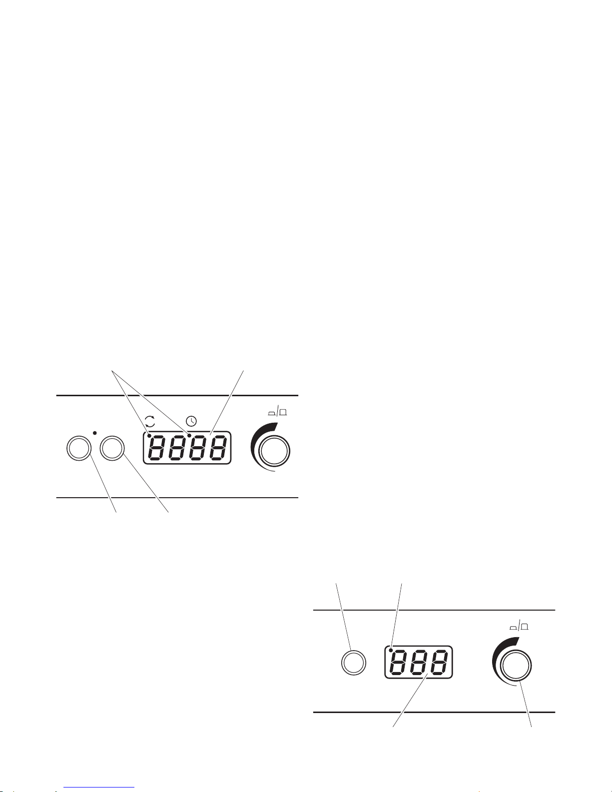
5. Operation
5.1 Setting the speed
Using the keypad at the base of the instrument,
switch the unit ON by pressing the control knob.
Press the mode button until a red dot shows in
the display below “rpm”. The display will then
show the last set speed. Adjust the speed by
turning the control knob. The minimum speed is
30rpm and the maximum, 300rpm.
Time/speed LED Red digital display
Once the correct speed is displayed press the
start/stop button to begin motion. The speed
can be adjusted without halting the unit. The
unit can be halted at any time by pressing the
start/stop button. If the door is opened while the
unit is in motion a warning alert will sound and
the motion will stop; the word “door” will also
be momentarily displayed on the screen. Close
the door to continue.
5.2 Setting the timer
In order to use the timer, stop the rotation and
press the mode button so that the red dot in the
display appears below “time”. The display will
show three horizontal lines or the last stored
time. Select the desired countdown time using
the control knob. The time will be displayed first
in minutes and seconds, next in hours and
minutes then in days and hours up to a
maximum of 9 days.
When the display shows the correct time, press
the start/stop button to begin operating. During
operation, motion can be paused at any time by
pressing the start/stop button. If the button is
pressed again, motion will start again and the
timer will continue to count down. The timer can
be adjusted without halting the unit. When the
timer reaches zero, the unit will automatically
stop and an alert will sound. If the door is
opened while the unit is counting down, a
warning alert will sound and the motion and
countdown will stop; the word “door” will also
be momentarily displayed on the screen. Close
the door to continue and the countdown will
resume from the point at which it was stopped.
N.B to disable the timer and revert to
continuous rotation, select - - - in the display
during timer mode.
5.3 Setting the temperature
Using the top control panel, switch the
temperature control unit ON by pressing the
control knob. Holding down the “press to set”
button, turn the knob until the correct
temperature is displayed. When holding the
“press to set” button of the SI600C, a set point
indicator will illuminate to confirm the set point.
Release the “press to set button”. The incubator
will then begin to heat to the set temperature.
The actual temperature inside the unit will be
displayed on the screen. The minimum set
temperature is ambient +5ºC (ambient -15°C or
5°C minimum for the SI600C) and the maximum,
60ºC.
on/off
temperature ºC
press to set
Start/stop button Mode button
Set point indicator (SI600C)Press to set
Red digital display Control knob

5
5.4 Incubation at sub-ambient temperatures
(SI600C only)
The connected chiller unit should be switched on
when it is required to incubate at around
ambient temperature or below. Above these
temperatures the chiller unit should be turned
off. The chiller coolant temperature should be
set at the required incubator temperature -15°C
and within its own recommended limits. For
example if an incubator temperature of 15°C is
required, the chiller coolant should be set to
0°C. To obtain the specification quoted the
coolent flow rate should be a minimum of 9 l/
min. The recommended operating pressure is 1.0
to 2.0bar. The maximum safe pressure is 4.0bar.
When using the chiller, check the condensate
collection container at regular intervals and that
the condensation outlet tube is not blocked.
Note that hazardous substances used within the
incubator could remain within the condensation
trap. The condensate should be disposed of in
the same manner as the substances used within
the incubator i.e. in a safe manner in compliance
with environmental legislation.
It is recommended that after a period of
prolonged use at low temperature the chiller unit
is turned off and the unit is allowed to run at
maximum temperature overnight to ensure that
any moisture within the unit is dried out.*
*Note that during the drying-out process the SI600C cannot be
assumed to meet all the safety requirements of 61010-1.
5.5 USB Connectivity
Your incubator has capability to connect to a PC
via USB for long term tracking of the incubator
temperature, whilst left overnight for instance.
Remove the waterproof cap from the USB port
on the incubator and connect the included cable.
Connect the other end of the cable to a free
USB port on your PC. The latest version of our
PC software is available for download from
www.stuart-equipment.com. Once downloaded,
select run the program and follow the on screen
commands.
6. Maintenance, servicing
and repair
WARNING: Ensure the unit is disconnected
from the mains electricity supply by
removing the mains power lead before
attempting maintenance or servicing.
This equipment does not require routine
servicing. The only maintenance required is to
clean internal and external surfaces with a damp
cloth and mild detergent. Spillages or splashes
should be cleaned up straightaway after isolating
the unit from the mains electricity supply. Allow
the unit to dry completely before operating
again.
When using the SI600C with a chiller unit:
❖ Check the condition of the tubing on a
regular basis.
❖ If the tubing or coolant needs replacing, do
not connect or disconnect the tubing until
the coolant is at room temperature.
❖ Avoid spillage of coolant when connecting or
disconnecting tubing by disconnecting the
top tube (Outlet) first to allow the coolant to
drain.
❖ If any of the tubes are blocked, do not
attempt to unblock them by inhaling or
blowing on the tubing. Replace the tube.
6.1 Repairs and support
Any repairs or replacement of parts MUST be
undertaken by suitably qualified personnel.
Only spare parts supplied or specified by
Cole-Parmer or its agent should be used.
Fitting of non-approved parts may affect the
performance of the safety features designed
into the instrument.
For a comprehensive list of parts required by
service engineers conducting internal repairs,
or to receive a service manual, please contact
the Service Department at;
cpservice@coleparmer.com
Tel: +44 (0)1785 810475
Quote both the model and serial number.
For any other technical enquiries, please contact
the Technical Support Department at:
cptechsupport@coleparmer.com
Tel: +44 (0)1785 810433

7. Accessories
Code Description
SI500/1 Tube holder 64 x 1.5ml tubes
SI500/2 Tube holder 25 x 15ml tubes
SI500/3 Tube holder 12 x 50ml tubes
SI500/4 Tube holder 16 x 30ml universal
container
RSSL1 Spare securing bar for SI500
SI600/1 Spare securing bar for SI600
SI600C-232 Washer
SI600C-233 90° connector
SI600C-240 Condensate tubing
SI600C-241 Coolant tubing
SBS4074 Jubilee clip
700198 Jubilee clip
8. Warranty
Cole-Parmer Ltd. warrants this instrument to be
free from defects in material and workmanship,
when used under normal laboratory conditions,
for a period of three (3) years. In the event of a
justified claim, Cole-Parmer will replace any
defective component or replace the unit free of
charge.
This warranty does NOT apply if damage is
caused by fire, accident, misuse, neglect,
incorrect adjustment or repair, damage caused by
installation, adaptation, modification, fitting of
non-approved parts or repair by unauthorised
personnel.
Cole-Parmer Ltd.
Beacon Road,
Stone, Staffordshire,
ST15 0SA, United Kingdom
Tel: +44 (0)1785 810475
Email: cpservice@coleparmer.com
Web: www.stuart-equipment.com
6

9. Specification
SI500 SI600 SI600C*
Technical specification
Temperature range Ambient +5ºC to 60ºC Ambient +5ºC to 60ºC +5ºC to 60ºC
Temperature display resolution 0.1ºC 0.1ºC 0.1ºC
Temperature accuracy1 ±0.5ºC ±0.5ºC ±0.5ºC
Temperature fluctuation1 ±0.5ºC (at 37ºC) ±0.5ºC (at 37ºC) ±0.5ºC (at 37ºC)
Temperature variation2 ±0.5ºC ±0.5ºC ±0.5ºC
Speed range 30 to 300 rpm 30 to 300 rpm 30 to 300 rpm
Orbit diameter 16mm 16mm 16mm
Warm up time 20-60˚C3 <30 min <30 min <30 min
Cool-down time 20-5°C
3 - -
<60 min
Maximum load 10kg 10kg 10kg
Maximum safe coolant pressure - - 4.0bar
Net weight 30kg 53kg 60kg
Heating power rating 250W 400W 400W
Electrical supply 230V, 50Hz, 300W 230V, 50Hz, 500W 230V, 50Hz, 500W
External dimensions
Height 522mm 640mm 640mm
Depth 474mm 542mm 542mm
Width 450mm 675mm 675mm
Incubator internal dimensions
Height 297mm 395mm 380mm
Depth 408mm 455mm 465mm
Width 422mm 625mm 625mm
Maximum vessel height 250mm 320mm 320mm
Platform size 335 x 335mm 525 x 390mm 525 x 390mm
Incubator capacity
2800ml Fernbach flasks 0 2 2
2000ml conical flasks 0 6 6
1000ml conical flasks 4 9 9
500ml conical flasks 9 15 15
Magnetic accessories 4 6 6
*Specification where cooling achieved using a Stuart SRC4 Recirculating Cooler. The cooling specifications may be
affected by the capability of the chiller unit used.
1
At 37°C, ambient 20°C +/- 2°C, no load, measured in the centre of the unit.
2
At 37°C, ambient 20°C +/- 2°C, no load, measured across the area of the shaker in the centre of the unit.
3
Ambient 20°C +/- 2°C.
7

8
start/stop mode
rpm
time
on/off
press
to
start
temperature ºC
on/off
o
rb
ita
l in
c
u
bato
r
S
I
5
00
start/stop mode
rpm
time
on/off
press
to
start
temperature ºC
on/off
o
rb
ita
l in
c
u
b
a
to
r
S
I
5
00
Panneau de
commande de
la température
Panneau de
commande de
la vitesse
Connecteur
USB
Orifice de positionnement
de porte-éprouvettes
optionnels
Plate-forme
rétractable
Bouton de verrouillage
de la plate-forme
rétractable
Français

9
AGITATEUR INCUBATEURS
SI500, SI600
Instructions d’utilisation
1. Introduction
Nous vous remercions d'avoir fait l'acquisition de
cet équipement Stuart. Pour profiter au mieux
des performances de cet équipement, lisez
attentivement ces instructions avant toute
utilisation. Avant de jeter l'emballage, vérifiez que
tous les éléments sont présents et en bon état.
Numéro de l'article Description
HH179(S) Cordons d'alimentation
équipés de prises R.-U.
HH180(S) Cordons d'alimentation
équipés de prises CEE
SI500-MAN Manuel d’instructions
I/FCALUSB Câble USB
RSSL1 ou SI600/1 Barres de fixation (4)
7001096 Label de garantie
SI600-214 Supports de pieds (2) et vis(4)
pour SI600 et SI600C
SI600C uniquement:
SI600C-232 Rondelle (2)
SI600C-233 Connecteurs à angle droit (2)
SI600C-240 Tuyau de condensat
SI600C-241 Tuyau de refroidissement (2)
SBS4074 Collier de serrage (1)
700198 Colliers de serrage (4)
Pour votre propre sécurité ainsi que pour celle
d'autrui, assurez-vous de lire et de parfaitement
comprendre les consignes de sécurité décrites
ci-dessous avant d'utiliser l'appareil.
2. Consignes de sécurité
Si l'appareil n'est pas utilisé conformément
aux directives détaillées dans ce manuel ou
avec des accessoires différents de ceux
recommandés par Cole-Parmer, la
protection fournie risque d'être inefficace.
Cet appareil est conçu pour fonctionner dans les
conditions environnementales suivantes:
❖ Utilisation à l'intérieur uniquement
❖ Utilisation dans un lieu correctement ventilé
❖ Température ambiante de +5ºC à +40ºC
❖ Altitude maximale de 2000m
❖ Taux d'humidité relative de 80% au plus
❖ Fluctuations de l'alimentation secteur ne
dépassant pas 10%
❖ Surtension de catégorie II IEC60364-4-443
❖ Degré de pollution 2
Avertissements et conditions de fonctionnement:
ATTENTION: OBJET LOURD. NE PAS
ESSAYER DE SOULEVER OU DE
TRANSPORTER L'APPAREIL SEUL.
❖ Laisser une distance minimum autour de
l'appareil 200mm (100mm à l'arrière) par
rapport aux murs ou aux autres éléments.
❖ Ne pas utiliser pour chauffer ou mélanger des
matières susceptibles de dégager des gaz, ou
de provoquer des explosions ou des
implosions.
❖ Ne pas utiliser ou installer l'appareil dans des
zones dangereuses.
❖ Ne jamais déplacer ou porter l'appareil
lorsqu'il est en fonctionnement ou connecté à
l'alimentation secteur.
❖ Pendant les soulèvements et les déplacements,
toujours soulever l’appareil par la base.
❖ Ne pas utiliser dans une atmosphère
dangereuse ou en présence de substances
dangereuses.
❖ S'assurer de l'équilibre de la charge.
❖ Ne pas tenter de stopper le mouvement de
l'appareil manuellement.
❖ Ne pas s'appuyer sur la porte ouverte du
SI600 ou SI600C car cela peut faire basculer
l'appareil, en particulier quand la plate-forme
est dépliée. En outre, ne pas laisser
l'incubateur sans surveillance quand la porte
est ouverte.
❖ La fixation des supports de pieds sur le SI600
et le SI600C est nécessaire avant emploi
(voir4.4).
❖ En cas de coupure de l'alimentation secteur,
l'appareil ne redémarrera pas à rétablissement
de l'alimentation. En cas d'interruption
mécanique (par exemple, en cas de calage du
moteur), l'appareil reprendra son
fonctionnement une fois la cause de
l'interruption corrigée.
❖ L'énergie mécanique peut provoquer le bris
des récipients en verre. À utiliser avec
précaution.

10
PRENDRE DES PRÉCAUTIONS LORS DU
RETRAIT DES RÉCIPIENTS DE
L'INCUBATEUR CAR CERTAINES PARTIES
PEUVENT ÊTRE CHAUDES.
3. Description générale
Les incubateurs orbitaux Stuart SI500, SI600 et
SI600C sont parfaits pour le mélange ou
l'aération d'échantillons biologiques variés dans
des conditions de contrôle précis de la
température. Sa plate-forme rotative dispose d'un
système de réglage numérique de la vitesse, pour
produire un mouvement circulaire uniforme et
régulier, avec une orbite de 16mm. Elle atteint
une vitesse de rotation de 30 à 300tr/min.
L'incubateur est également équipé d'une
minuterie numérique réglable qui contrôle l'arrêt
automatique de l'appareil une fois le délai
prédéfini écoulé (pas d'1seconde à 1heure, pas
d'1minute à 24heures ou pas d'1heure à
9jours). La plate-forme d'agitation est équipée
d'un mécanisme coulissant pour permettre un
accès facile aux récipients d'incubation. La
température est contrôlée par un système de
réglage simple par pression sur un bouton, par
intervalles de 0,1ºC, de la température ambiante
+5°C et jusqu'à 60ºC.
Le modèle SI600C peut également se brancher
sur un refroidisseur à circulation pour les
applications nécessitant des températures
inférieures à la température ambiante
(température ambiante -15°C, minimum 5°C).
Les incubateurs sont livrés avec un système de
réceptacles totalement réglable afin d'accueillir
une large gamme de flacons et de bouteilles. Les
accessoires optionnels comportent des casiers
pouvant accueillir des éprouvettes de 1,5ml,
15ml et 50ml.
4. Préparation à l'utilisation
4.1 Installation électrique
CET APPAREIL DOIT ÊTRE MIS À LA TERRE.
Avant de connecter l'appareil, assurez-vous de lire
et de parfaitement comprendre ces instructions.
Vérifiez que l'alimentation secteur correspond aux
caractéristiques indiquées sur la plaque
signalétique. Cet appareil est conçu pour une
utilisation avec une alimentation de 230V et
50Hz. La consommation électrique de l'appareil
est de 300W pour le SI500 et de 500W pour le
SI600 et le SI600C. S'assurer qu'un cordon
d'alimentation correspondant à la tension requise
est utilisé. L'instrument est livré avec une prise
CEI à l'arrière pour le branchement à
l'alimentation secteur. Pour isoler l’instrument de
l'alimentation électrique, débrancher le cordon
d’alimentation.
Attention: des fusibles sont installés sur les
lignes de phase et de neutre.
Fusibles:
Fusibles de 230V - 3,15A anti-surtensions. Pour
toutes les autres tensions, remplacez toujours un
fusible par un fusible de type et de calibre
équivalents. Vous pouvez également vous
reporter à la plaque signalétique pour connaître
le type et le calibre des fusibles.
L'appareil est fourni avec deux cordons
d'alimentation équipés de fiches CEI. L'un de ces
cordons est équipé d'une fiche britannique à
3broches et l'autre est équipé d'une fiche
“Schuko” à deux broches. Choisissez le cordon
d'alimentation adapté à votre installation
électrique et mettez l'autre de côté. Si aucun des
cordons ne convient, utilisez le cordon équipé
d'une fiche britannique après avoir remplacé
celle-ci par une fiche appropriée. Pour ce faire,
coupez le cordon du côté de la fiche moulée,
préparez les fils et connectez-les à une fiche
démontable, conformément aux instructions
fournies avec cette dernière.
IL EST IMPORTANT QUE CETTE OPÉRATION
SOIT RÉALISÉE PAR UN ÉLECTRICIEN
QUALIFIÉ UNIQUEMENT.
REMARQUE: Reportez-vous à la plaque
signalétique de l'appareil afin de vous assurer que
la fiche et les fusibles sont adaptés à la tension et
à la puissance mentionnées. Les couleurs des fils
du cordon d'alimentation sont les suivantes :
PHASE - MARRON
NEUTRE - BLEU
TERRE - VERT/JAUNE
Le cordon d'alimentation approprié doit être
connecté à l'appareil AVANT de le connecter à
11
une prise secteur. Si le cordon d'alimentation doit
être remplacé, utilisez un câble d'1mm2 de type
H05VV-F harmonisé, connecté à une fiche
IEC320. Remarque: Le cordon d'alimentation
équipé d'une fiche britannique est protégé par un
fusible de 10 A monté dans la partie supérieure
de la fiche.
EN CAS DE DOUTE, CONSULTEZ UN
ÉLECTRICIEN QUALIFIÉ.
4.2 Positionnement
Placer l'appareil sur une surface solide, plane, non
glissante, en s'assurant de disposer d'un espace
libre suffisant de tous les côtés garantissant
l'absence de tout contact pendant l'utilisation.
Laisser au moins 100mm à l'arrière pour faciliter
l’accès au cordon d'alimentation électrique et
200mm de chaque côté de l'instrument.
4.3 Connexion de l’appareil SI600C à un
refroidisseur à circulation
Pour permettre une incubation à une température
inférieure à la température ambiante, le SI600C
doit être connecté à un refroidisseur à circulation.
S’assurer que le refroidisseur se trouve sur une
surface solide et qu’il ne vibre pas lorsque
l’incubateur fonctionne à vitesse maximale.
Brancher une extrémité du tuyau de condensat
au tuyau d’évacuation du condensat et l’autre
extrémité au récipient de collecte du condensat
situé à une hauteur inférieure à celle du tuyau
d’évacuation du condensat. S’assurer que le
récipient de collecte de condensat peut contenir
une quantité de liquide au moins égale à la
quantité de liquide de refroidissement.
Fixer les connecteurs à angle droit fournis aux
deux connecteurs situés à l’arrière de l’appareil
(INLET (entrée) et OUTLET (sortie)). Brancher les
tuyaux en EPDM d’1,5m de long et de 8mm de
diamètre interne sur les connecteurs et les
maintenir en place à l’aide des colliers de serrage.
Connecter l’autre extrémité des tuyaux aux ports
du refroidisseur en veillant à ce qu’aucune
déformation de tuyau ne restreigne le flux. Ne
pas trop serrer.
Pour des performances optimales, utiliser des
tuyaux de connexion aussi courts que possible. Se
référer aux spécifications du refroidisseur pour les
longueurs de tuyau acceptables et la hauteur de
tête maximale. Placer le refroidisseur à un
emplacement sûr afin d’éviter toute collision
accidentelle.
Liquide de refroidissement
Pour les températures inférieures à 10°C, ou
chaque fois que cela est recommandé dans le
manuel, un liquide de refroidissement doit être
utilisé. Un mélange 1:1 d’éthylène glycol de
laboratoire et d’eau est recommandé. NE PAS
utiliser d’eau désionisée.
ATTENTION:
❖ Ne pas utiliser de liquides de
refroidissement inflammables.
❖ Se référer au manuel du refroidisseur
pour s’assurer qu’un liquide compatible
est utilisé.
❖ Le liquide doit être compatible avec les
pièces d’incubateur en laiton, cuivre,
caoutchouc EPDM et nickel qui entrent
en contact avec lui.
Lors de l’utilisation d’un liquide de
refroidissement à une température inférieure à
0°C, un condensat peut se former sur les tuyaux.
Ce risque peut être réduit en isolant les tuyaux.
S’assurer que les tuyaux ne présentent aucune
déformation ni aucune restriction et qu’ils sont
correctement maintenus en place à l’aide de
serre-câbles, le cas échéant. Déterminer si des
fuites sont présentes en allumant la pompe du
refroidisseur avant de fixer le SI600C en place sur
la paillasse.
Port de sortie
Tuyau
d’evacuation
du condensat
Port
d’entrée
Vers le
refroidisseur
Connecteurs
à angle droit
Vers le récipient
de collecte du
condensat
12
4.4 Fixation des supports de pieds (SI600 et
SI600C)
Pour empêcher l'appareil de vibrer ou de se
déplacer pendant son utilisation, le SI600 et le
SI600C doivent être fixés à la paillasse à l'aide de
supports de pieds. Deux supports de pieds sont
fournis pour la fixation des pieds arrière.
S'assurer que l'appareil est positionné
correctement. Depuis les côtés de l'appareil, faire
glisser les supports de pieds autour de chacun
des pieds arrière (1). Les fixer en place à l'aide
des deux vis n°8 x 20mm (2).
Brancher l'alimentation électrique - NE PAS
METTRE SOUS TENSION.
4.5 Chargement
Attention: tenir les objets lâches à l’écart de
la porte avant de l’ouvrir.
Ouvrir la porte. Tirer vers l'extérieur les deux
molettes à ressort noires de chaque côté du
support, en direction des côtés de l'incubateur et
sortir la plate-forme du support de l'incubateur
vers soi.
Charger le support avec les récipients, si
nécessaire en réglant les barres de fixation
caoutchoutées. S'assurer que la charge est
répartie de façon équilibrée et qu'elle ne dépasse
pas la charge maximale autorisée.
Repousser doucement la plate-forme dans
l'incubateur jusqu'à ce qu'elle se verrouille en
place. Fermer la porte.
Remarque: assurez-vous que la plate-forme
rétractable a émis un clic et s'est bloquée
dans la position appropriée avant de mettre
l'appareil en marche. Dans le cas contraire,
vous risqueriez d'endommager l'appareil.
5. Utilisation
5.1 Réglage de la vitesse
Mettez l'appareil sous tension (ON) en appuyant
sur le bouton de commande du panneau situé à
la base de l'appareil. Appuyez sur le bouton
“mode” jusqu'à ce qu'un point rouge apparaisse
sur l'écran d'affichage, sous l'indication “rpm”.
L'écran d'affichage indique alors la dernière
vitesse définie. Réglez la vitesse en tournant le
bouton de commande. La vitesse minimale est de
30tr/min et la vitesse maximale est de 300tr/
min.
Lorsque la vitesse souhaitée s'affiche, appuyez sur
le bouton “start/stop” (marche/arrêt) pour lancer
la rotation. Il est possible de régler la vitesse sans
arrêter l'appareil. Vous pouvez arrêter l'appareil à
tout moment en appuyant sur le bouton “start/
stop” (marche/arrêt). Si la porte est ouverte alors
que l'appareil est en fonctionnement, une alarme
retentit et le mouvement de l'appareil est
interrompu. Le mot “door” (porte) s'affiche à
l'écran durant quelques instants. Refermez la
porte pour continuer.
5.2 Réglage de la minuterie
Pour utiliser la minuterie, arrêtez la rotation de
l'appareil et appuyez sur le bouton “mode” afin
qu'un point rouge s'affiche à l'écran sous
l'indication “time” (durée). L'écran affiche alors
trois lignes horizontales ou la dernière durée
mémorisée. Sélectionnez la durée de compte à
rebours souhaitée à l'aide du bouton de
commande. La durée de compte à rebours
s'affiche tout d'abord en minutes et en secondes,
puis en heures et en minutes et enfin en jours et
en heures, jusqu'à un maximum de 9jours.
1
2
on/off
rpm time
start/stop mode
Voyant de
minuterie/vitesse
Affichage
digital rouge
Bouton “start/stop”
(marche/arrêt)
Bouton “mode”
 Loading...