

Microcentrifuge
Instruction Manual
STU0003 / Version 1.0
Introduction
Thank you for purchasing this Stuart product. To get the best performance from the equipment, and for
your own safety, please read these instructions carefully before use.
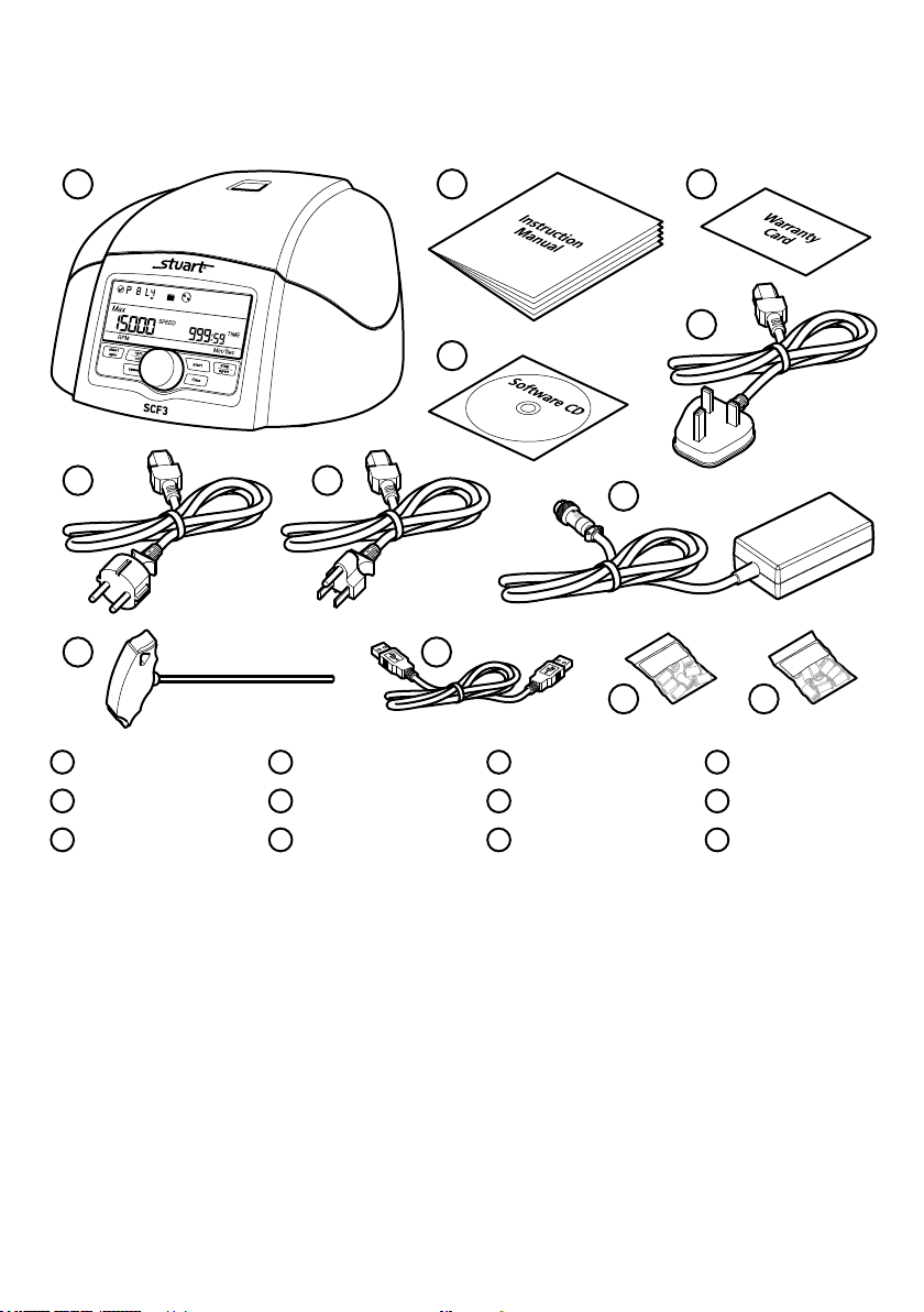
Before discarding the packaging check that all parts are present and correct.
1
2
3
5
4
6
7
8
9 10
11 12
1 SCF3 2 Instruction manual 3 Warranty card 4 Software CD
5 UK power lead 6 EU power lead 7 US power lead 8 Power adaptor
9 ‘T’ allen key 10 USB lead 11 Micro tube adaptor 12 Micro tube adaptor
0.2/0.3ml x12 0.4/0.5ml x 12
Note: Before rst use, open the centrifuge and remove all the packaging from the rotor chamber. You will need to
switch the centrifuge ON before the lid can be opened.
This equipment is designed to operate under the following conditions:
v For indoor use only
v Use in a well ventilated area
v Ambient temperature range 5°C to 35°C (41°F to 104°F)
v Altitude to 2000 m (6500 ft)
v Relative humidity not exceeding 60% and free from condensation
v Mains supply uctuations not exceeding 10% of nominal
v Overvoltage category II IEC60364-4-443
v Pollution degree 2 IEC664
v Use with a minimum distance all round of 300 mm (12 in.) from walls or other items
If the equipment is not used in the manner described in this manual and with accessories other than those
recommended by the manufacturer, the protection provided may be impaired.
2
General Description
The SCF3 is a compact microcentrifuge for the centrifugation of microfuge tubes ranging from 0.2ml to 2.0ml or
2 x 8 PCR tube strips at speeds of up to 15000rpm. The unit is supplied with a pre-installed 12 x 0.2/2ml rotor
and a 2 x 8 0.2ml strip rotor can be ordered. The rotors are easily installed without the use of tools. Centrifugation
speed can be displayed as either rpm or rcf and the timer can be set for run times of between 30 seconds to 999
minutes and innite mode. In addition, a short spin button spins the rotor to the preset rpm then promptly
decelerates. For safety, the door of the SCF3 remains locked while the rotor is in motion.
Important Safety Advice
Users should be aware of the following safety advice:
v SHOCK HAZARDS OR UNSAFE PRACTICES ARE DANGEROUS as they can cause severe personal injury, re
or death.
v DO NOT use combustible substances near hot objects.
v DO NOT use the equipment in hazardous atmospheres.
v DO NOT operate or handle any part of the product with wet hands or use on surfaces that may become ooded.
v NEVER move the product while still connected to the power supply.
v HIGH TEMPERATURES ARE DANGEROUS as they can cause serious burns to operators and ignite combustible
material.
v USE CARE AND WEAR PROTECTIVE GLOVES TO PROTECT HANDS.
v NEVER lift or carry the instrument during operation.
v DO NOT position the unit so that it is difcult to disconnect from the mains supply using the mains plug.
v The mains outlet socket used should be located close to the equipment and readily identiable and accessible
to users.
v DO NOT leave equipment switched on and it is not recommended to leave any heating apparatus unattended
during operation.
v The unit should be carried using both hands.
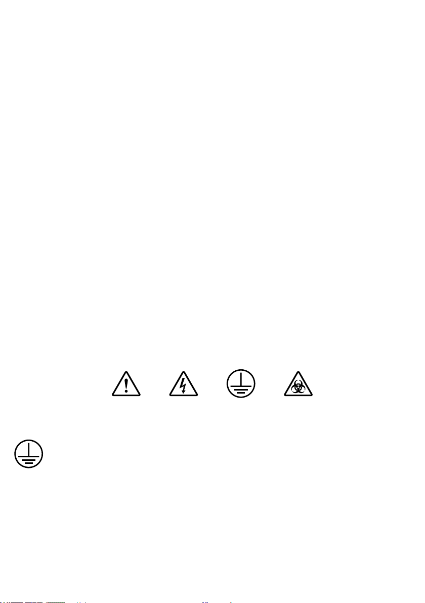
Symbols Dened
WARNING EARTHRISK OF
ELECTRIC SHOCK
BIOHAZARD
Electrical Requirements
THIS INSTRUMENT MUST BE GROUNDED
Before connection please ensure that the line supply corresponds to the power requirements below:
Power: 72W Supply requirements: 100 - 230 VAC, 50-60Hz
The unit is provided with a power adaptor and three power cables consisting of a UK 3-pin and a “Schuko” 2-pin
plug for 230 V installations and a NEMA 5-15 plug for 120 V installations.
Choose the power cable appropriate for your electrical installation and discard the other. Should neither power cable
be suitable for connecting to the power supply, replace the plug with a suitable alternative..
THIS OPERATION SHOULD ONLY BE UNDERTAKEN BY A QUALIFIED ELECTRICIAN.
3

NOTE: Refer to the equipment rating plate to ensure that the plug and fusing are suitable for the voltage and
wattage stated. The wires in the mains cable are as follows:
230V 120V
BROWN - HOT/LIVE BLACK - HOT/LIVE
BLUE - NEUTRAL WHITE - NEUTRAL
GREEN/YELLOW – EARTH GREEN - EARTH
The appropriate power cable and power adaptor combination should be connected to the instrument BEFORE
connection to the mains supply. Should the mains lead require replacement, a cable of 1.25mm² (AWG16) of
harmonised code H05VV-F connected to an IEC320 plug should be used.
IF IN DOUBT CONSULT A QUALIFIED ELECTRICIAN
Product Features
v Imbalance detector with auto cutoff
v Large back light digital LCD display
v Maximum speed of 15000 RPM/15596 x g RCF
v USB port for remote terminal control capability
v Remote operation with data logger
v Lid safety interlock and auto lid open
v Convenient and easy user interface
v Quick acceleration and deceleration time
v One touch short spin centrifugation
v Last run memory feature
v Emergency lid release during power cut-off
v Countdown timer
v Automatic internal diagnosis and error display
v Speed setting by RPM/RCF mode
v Fully autoclaveable high strength aluminum rotor with metal lid
v Small footprint
4
Operation
Before Use
Place the unit on a rm, level surface, ensuring that all four feet on the base of the unit are positioned on the
surface rmly. Avoid installation on a slippery surface or on a surface prone to vibration.
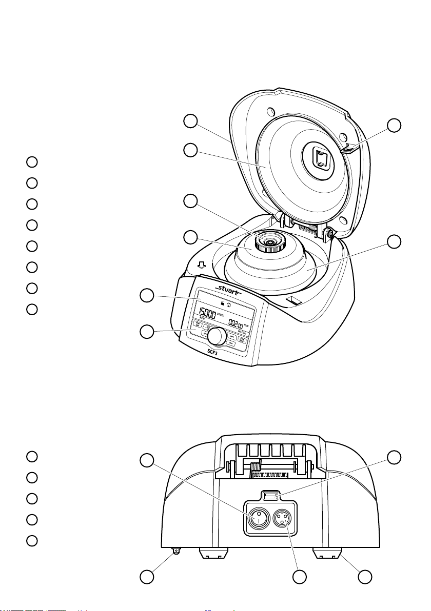
SCF3 Overview
Main View
1 Centrifuge lid
2 Aluminium protection lid
3 Rotor lid locking nutl
4 Rotor lid
5 Display
6 Control panel
7 Lid lock
8 Rotor
1
7
2
3
4
8
5
6
Rear View
9 ON/OFF switch
10 Emergency lid release
11 USB Connection
12 Power input
13 Non-slip feet
9
10
11
12 13
5

SCF3 Control Panel and Display
Control Panel
46 5 17
2 3
1
2
3
4
5
6
7
- Press to stop. Lid opens automatically after rotor has come to a stop.
- Press to select speed mode. Turn rotary dial (4) to set desired run speed.
- Press to select time mode. Turn rotary dial (4) to set desired run time.
- Use to set speed and time. Rotate clockwise/anti-clockwise to
increase/decrease values.
- Press to start the centrifuge.
- Press to set/read rpm/rcf values.
- Press and hold after setting the required speed to run the centrifuge for a
short time.
6
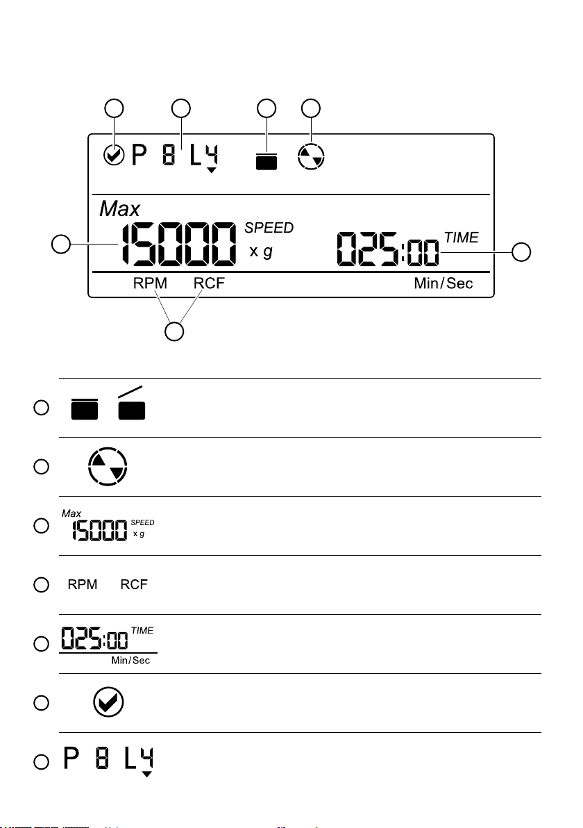
Display
17 26
3
1
Closed Open
2
3
4
5
5
4
- Indicates lid status.
- Indicates centrifuge status. The symbol will rotate when the centrifuge is
running and will be static when the centrifuge has stopped
- Indicates the speed at which the centrifuge is running. x g indicates the
value in RCF mode.
or
- Indicates RPM or RCF mode and shows corresponding values.
- Indicates how long the centrifuge will run. The timer is a countdown timer
and displays in Min/Sec mode.
6
7
- Indicates the centrifuge is connected via usb. When this mode is
active, control panel buttons (except stop button) will be deactivated.
- Indicates the specic program details being used. Applicable in remote
operation mode.
7

Connecting the power adaptor
1. Ensure the power switch is OFF before connecting the power adaptor.
2. Connect the appropriate power cable to the power adaptor.
3. Connect the power adaptor to the centrifuge. Ensure you align the notch on the power adaptor with the rib
on the centrifuge. If they are aligned correctly the plug will go in easily. IF THESE ARE NOT ALIGNED YOU
WILL NOT BE ABLE TO CONNECT THE POWER, DO NOT FORCE TOGETHER!
4. Once the plug is in position turn the locking ring clockwise to secure the connection.
Loading the rotor
Always check the rotor is tted correctly, rmly tightened and balanced before centrifugation. Below are examples
of correctly and incorrectly balanced rotors.
The samples in the tubes should be of equal volume and must exceed the maximum capacity of 12 x 1.5/2ml. Do
not use with liquid with a density higher than 1.2g/ml for full load operation.
Prior to centrifugation check the tubes for damage and they are loaded correctly. Damaged or incorrectly loaded
tubes can cause vibration or imbalance which can lead to serious damage to the unit.
If the tubes are not loaded symmetrically then the imbalance detector will cut off the running centrifuge for device
& user safety. This will stop the centrifuge and “Err 55” will be seen indicating tubes are not loaded symmetrically.
To resume operation, load tubes symmetrically & restart the centrifuge.
8

Rotor removal and replacement
The rotor comes pre‐installed with the centrifuge. If you want to remove or replace the rotor, follow the
instructions below.
1. Open the lid.
2. Remove the Rotor lid by turning the Rotor lid nut anti-clockwise by hand.
3. Use the T ‐ allen key to loosen the rotor nut by turning it anti-clockwise and remove.
4. Remove the Rotor by lifting it up and off the Motor shaft.
5. Load the replacement rotor onto the Motor shaft
6. Use the T ‐ allen key to tighten the Rotor nut by turning it clockwise.
7. Place the Rotor lid on the rotor and turn the Rotor lid nut clockwise by hand to tighten.
Note: Check the Rotor is correctly tted and the Rotor nut and Rotor lid nut are rmly tightened before
running the next program.
Rotor lid nut
Rotor lid
Rotor nut
Rotor
Motor shaft
T - allen key
9

Starting the SCF3 centrifuge
After connecting the power adaptor, switch the power ON at the rear side of the centrifuge. Check the rotor is
tted correctly, rmly tightened and balanced before use. Centrifuge will not operate with an open lid.
Note: Wait 3 seconds between turning off and turning on the centrifuge. DO NOT turn the centrifuge off and on
instantly.
Setting the speed and time
After closing the centrifuge lid; press the speed button to select the speed setting. Now turn the rotary dial
clockwise to increase the speed value and rotate counter clockwise to decrease the speed value. The
minimum and maximum speed of the centrifuge is 500 RPM and 15000 RPM respectively.
v Pressing the speed button “ONCE” will make the speed change in intervals of 1000 RPMs. For example: if the
speed is 10000 RPM, then next speed will be 11000 RPM.
v Pressing the speed button “TWICE” will make the speed change in intervals of 100 RPMs. For example: if the
speed is 10000 RPM, then next speed will be 10100 RPM.
v Pressing the speed button more than 2 times will restart the process.
v The input will be accepted if the setting dial is left idle for 3 seconds. The value will blink ve times to
indicate acceptance.
Press the time button to select the time setting. Now turn the rotary dial clockwise to increase the time and
rotate counter clockwise to decrease the time. The centrifuge timer is set to run between 30 seconds to 999
minutes or operated in innite time mode. Innite timer will be indicated by c: c in display. The minimum time
setting is 30 seconds. The timer in the centrifuge is a countdown timer and the time in the display will be in “Min/
Sec” mode. The same will be shown on the display.
v Pressing the time button “ONCE” will make the time change in interval of minutes. For example: if the time is
005:00 (5 Mins 0 Sec), then the next time will be 006:00 (6 Mins 0 Sec).
v Pressing the time button “TWICE” will make the time change in interval of seconds. For example: if time is
005:00 (5 Mins 0 Sec), then next time will be 005:01 (5 Mins 1 Sec).
v Pressing the time button more than 2 times will restart the process.
v The input will be accepted if the setting dial is left idle for 3 seconds. The value will blink ve times to
indicate acceptance.
Press the start button to start operation and press stop/open button to stop the ongoing operation. When the
centrifuge is running the symbol “ ” will be rotating. Pressing the stop/open button will stop the operation.
The centrifuge lid will automatically open once the rotor comes to a stop. If the program running time ends, the
centrifuge will stop and the lid will automatically open. When the centrifuge is not running the symbol “ ” will
be stable. To open the lid without running the centrifuge, press the stop/open button.
Note: Speed and time can be changed while the centrifuge is running. Press the speed/time button and follow
the above steps for setting speed/time. Once the speed/time is changed during centrifugation it will remain for the
rest of centrifugation cycle. Speed/time can be changed multiple times during the centrifugation cycle.
C C
Switching to RCF display
Press rpm/rcf button to change the mode from RPM to RCF (Relative centrifugal force). After pressing the button
the display will show the speed in RCF. Maximum RCF speed of the centrifuge is 15596 x g. The system will
automatically convert the values from RPM to RCF and vice versa.
10

Short spin centrifugation
Short Spin Centrifugation is the feature for short/pulse run. It will run as long as the short spin button is pressed.
Set rotational speed prior to short spin as required. During the short spin the timer will be in incremental mode.
After releasing short spin button the time in the display will show duration of short spin.
Opening the centrifuge lid in power failure
Disconnect the centrifuge from the power supply. Wait until the rotor has come to a standstill (this may take time).
Once the rotor has stopped, pull down the emergency lid release cap below the centrifuge. This will open the
centrifuge lid.
Emergency lid release cap
Imbalance detection
The centrifuge comes with an imbalance detection safety feature. When the rotor is not loaded symmetrically, the
imbalance detector gets activated and stops any centrifugation. Error message “Err 55” will be shown on the
display. Correct the imbalance load using the method described in the Loading the Rotor section (see page 8).
After correcting the imbalance, turn off the centrifuge & turn it back on. The values will be the same as set before
the imbalance occurred. The imbalance detection feature cannot be deactivated, as it is a factory tted safety
feature.
Remote operation and programming
For programming and remote operation the centrifuge needs to be connected to a computer.
System requirements
The Graphical user interface (GUI hereafter) software and data logger le require at least the following system to
operate:
v Operation System: Windows® 7 with i3 Processor or higher with 32 bit or 64 bit operating system and
Windows® XP Sp3.
v Microsoft .NET framework 4 and Microsoft Ofce Excel 2007 or 2010 is required for operating GUI.
Installing GUI software
GUI Software CD is provided with the centrifuge kit. Install the software from the CD by running the setup le.
After installation the GUI software icon and centrifuge data logger le will appear on the desktop.
11

Connecting USB cable
Connect the USB cable to the centrifuge and another side to computer USB port. Without the USB connection the
centrifuge will not operate through the software. USB connection is shown below.
After the USB has been connected a symbol at the top left of the centrifuge display will appear to conrm and
indicate that the centrifuge is recognizing the connection.
USB connected
Once the USB cord is connected, the centrifuge unit controls will be disabled. The centrifuge can now be run using
the program. Only the stop/open button will be functional on the control panel.
Understanding the GUI and operation
After installing the GUI software, open the GUI software by double clicking the software icon. The following GUI
window will open on the computer screen.
12

Com port connecting and disconnecting
Drop down box
Text box
Once you connect the USB cable, the Com port for the centrifuge is detected automatically. Click on the Connect
button to connect centrifuge and computer for remote operation. After connection, the Text box will show
COM3, Centrifuge Connected.
Note: If any other device is connected after connecting the centrifuge then the Com port software gets updated.
Select the centrifuge Com port from the Com port Drop down box and click Connect to reconnect the centrifuge.
Note: Once the software is connected, the buttons on the centrifuge are deactivated and only stop/open button
will operate.
The centrifuge details
After the centrifuge has been connected, the centrifuge ID and version will display in the GUI screen. The
operation number shows the number of operations performed using the software.
Setting a program
Remote operation provides 99 programs with 4 lines maximum per program. It can be used to pre‐set and save
programs for specic and or regular operations. Below is an example of a program:
Line 1. Run for 2 minutes and 7 seconds with speed 15000 RPM
Line 2. Then take a pause of 30 seconds
Line 3. Then run centrifuge for 3 minutes and 22 seconds with speed of 7500 RPM
Line 4. Then take a pause of 4 minutes and 15 seconds
Note: There is delay of 8 seconds between all 4 lines.
COM3
COM3 , Centrifuge Connected
Connect
Buttons
Disconnect
Program scroll
Speed up/down Time up/down
Save
13

After completing at least one program line, the centrifuge display will change as shown below.
At least 1
program
line lled
Click on the Program scroll button to select the required program out of the total 99 programs you wish to set.
Starting with Line 1, click on Speed up/down buttons to select speed required, speed can be set only in RPM mode.
Click on Time up/down buttons to select time required. Up to 4 lines of a program can be saved. Operation will
always start from the 1st line. After changing speed and time for centrifugation according to user requirement
click on the Save button to save/set the program. Follow the same procedure for other lines of the program as
required.
Program note and sample numbers
Users can write the details of each sample used for centrifugation for reference purposes. Users can also write
General Notes regarding the sample used, operation details or any other specic information which is worth
mentioning in Program / General Note text box as shown in the diagram below. The data entered here will be
saved in the data log report.
1202 1202
2105 2105
6598 6598
1235 1235
1378 1378
5768 5768
5, 6, 11, 12 has sample number =
3205
Click on the CLEAR button to clear the sample number and general note details of the program.
Pre‐set program selection and operation
Click on the Program scroll button to select the required pre‐set program out of total 99 programs.
14

After selecting the required program, click on the START button
to start the operation. Operation will start from 1st line of the
selected program. There is a delay pause of 8 seconds between
all 4 lines. Once the 1st line operation is over it will wait for 8
seconds to start the 2nd line operation. During the operation all
the buttons on the device and boxes of the GUI will be disabled
except the STOP/OPEN button. When the centrifuge is running
the symbol in the GUI will rotate.
Stop operation
Click on STOP/OPEN button to stop the ongoing operation. The
centrifuge lid opens automatically when the rotor comes to a
standstill. Users can also stop the ongoing operation by pressing
STOP/OPEN button on the device. The lid status will be indicated
on the GUI screen.
Active line speed display
The Speed box is used to read the speed value of active lines of
the program. For example: if line 3 of the 46th program is running
then the Speed box will display the speed value of line 3 of the
46th program. It can be used to change the speed value of the
active line.
Click on RPM or RCF button to read speed value in RPM or RCF
mode for active line.
Active line time display
Time box is used to read the remaining time value of active lines
of the program. For example: if line 3 of the 46th program is
running then the Time box will display the remaining time value
of line 3 of the 46th program. This is a countdown timer.
Short spin centrifugation
After setting required speed click the Short Spin button for short
spin operation. The timer display in this mode is incremated in
seconds. During short spin operation the Time box will disable
as the timer converts to a count up timer. Press the stop/open
button to stop the short spin operation.
Centrifuge lid status
The images will be displayed in the screen according to the status
of the lid.
15

Centrifuge status
This symbol shows the centrifuge status. When the centrifuge is running the symbol rotates and when centrifuge
is not running the symbol is static.
Note: Centrifuge will get connected to a computer only if the USB cord is connected to both centrifuge and
computer. Proper selection of centrifuge Com port is necessary to enable the remote operation.
Note: It is highly recommended not to use or work on any other application or do online work while GUI is operating.
Data Log
The remote operation comes with a data log features. All operations performed through the GUI will be saved as
an excel sheet. With the help of the data log, users can view and make a print out of the previously performed
operations.
Users can access the data log le from their desktop. Data logger le named “Centrifuge_Data_Logger” will generate automatically on the desktop of the user’s computer once the operation is performed.
The following type of operation details will be saved in an excel sheet.
Note: The GUI software will not operate if “Centrifuge_Data_Logger” le is open.
Ensure to close the log sheet before remote operation.
16

Maintenance, Servicing and Cleaning
HOT: Before attempting any maintenance, servicing or cleaning, ensure that the unit is cool,
and disconnect from the power supply.
WARNING: Ensure the unit is disconnected from the power supply before attempting any
maintenance, servicing or cleaning.
The rotor and the outside of the centrifuge should be cleaned regularly with a moist cloth.
Ensure that while cleaning the unit it is not plugged in.
Wear protective gloves and safety glasses while operating and cleaning the device.
The brushless motor in the centrifuge does not require routine maintenance. Any required service should be
performed by authorized, qualied personnel only. Repairs performed by unauthorized personnel may void the
warranty.
Always keep the centrifuge housing, rotor chamber, rotor and rotor accessories clean. All parts should be wiped
down periodically with a soft cloth. For more thorough cleaning, use a neutral cleaning agent (Ph between 6 and
8) applied with a soft cloth. Excessive amounts of liquid should be avoided. Liquid should not come into contact
with the motor.
After cleaning, ensure that all parts are dried.
It is important to regularly clean the rotor.
If the rotor chamber needs cleaning, clean it with a cloth or a sponge moistened with a neutral detergent solution
(like water).
Do not place the rotor into the cleaning solution!
Preventative maintenance should include keeping the product clean by protecting it from spillage, contamination
or corrosive environments. If in doubt, please conrm that any intended method of decontamination will not
damage the equipment by contacting Cole-Parmer.
WARNING: This product does not contain bio‐seals as per IEC/EN/CSA 61010‐2‐20 and cannot provide any level
of containment in case of a spill or release of toxic, radioactive, or pathogenic micro‐organisms thus these materials are not recommended to be used in this product.
NOTE: Do not use solvents for cleaning any parts of this equipment.
In Case of Accidental Spillage
WARNING: DO NOT TOUCH IF A SPILLAGE/BREAKAGE HAS OCCURRED. DISCONNECT THE
POWER DIRECTLY AT THE POWER SUPPLY SOURCE.
If any part of the unit has been exposed to liquid, it cannot be assumed to meet all the safety requirements of EN
61010-2-020 until the drying out process has been fully completed and all safety requirements are met before the
unit is used again.
17

In Case of Contamination
WARNING: THE FOLLOWING PROCEDURE IS INTENDED AS A GUIDE. SHOULD SPILLAGE OF A
TOXIC OR HAZARDOUS FLUID OCCUR, THEN ADDITIONAL SPECIAL PRECAUTIONS MAY
BE NECESSARY.
If the equipment has been exposed to contamination, the Responsible Body is responsible for carrying out
appropriate decontamination. If hazardous material has been spilt on or inside the equipment, decontamination
should only be undertaken under the control of the Responsible Body with due recognition of possible hazards.
Before using any cleaning or decontamination method, the Responsible Body should check with the manufacturer
that the proposed method will not damage the equipment. Prior to further use, the Responsible Body shall check
the electrical safety of the unit. Only if all safety requirements are met can the unit be used again.
NOTE: In the event of this equipment or any part of the unit becoming damaged or requiring service, the item(s)
should be returned to the manufacturer for repair accompanied by a decontamination certicate. Copies of the
Certicate are available from the Distributor/Manufacturer.
At the end of its service life, the product must be accompanied by a Decontamination Certicate.
Repairs and Support
Any repairs or replacement of parts MUST be undertaken by suitably qualied personnel. Only spare parts supplied
or specied by Cole-Parmer or its agents should be used. Fitting of non-approved parts may affect the performance
and safety features designed into the instrument. For a comprehensive list of parts required by service engineers
conducting internal repairs please contact the service department quoting the model and serial number:
Email: cpservice@coleparmer.com
Tel: +44 (0)1785 810475
For any other technical enquiries please contact the Technical Support Department at;
Email: cptechsupport@coleparmer.com
Tel: +44 (0)1785 810433
Warranty
Cole-Parmer Ltd. warrants this instrument to be free from defects in material and workmanship, when used under
normal laboratory conditions, for a period of 3 years. In the event of a justied claim Cole-Parmer will replace any
defective component or replace the unit free of charge. This warranty does NOT apply if damage is caused by re,
accident, misuse, neglect, incorrect adjustment or repair, damage caused by incorrect installation, adaptation,
modication, tting of non-approved parts or repair by unauthorised personnel.
Cole-Parmer Ltd,
Beacon Road,
Stone,
Staffordshire,
ST15 0SA,
United Kingdom
Email: cpservice@coleparmer.com
Tel: +44 (0)1785 810475
Web: www.stuart-equipment.com
18

Spares and Accessories
Please contact your local sales specialist or email cpspares@coleparmer to enquire about available spares.
Please visit www.stuart-equipment.com for a full list of available accessories.
Technical Specication
General Specication
Motor type Brushless DC motor
Maximum speed 15000 rpm
Run time
Speed setting
Speed accuracy
Maximum volume
Maximum RCF
Ambient temperature
Permissable relative moisture
Air pressure
Acceleration time
Deacceleration time
Noise level
Input power
Output power
Power consumption
30 seconds to 999 minutes and innite mode
Variable: 500 - 15000 rpm
± 100 rpm
12 x 2ml (microtubes)
15596 x g
5 - 40ºC
<80%
80 to 106 kPa
30 seconds
40 seconds
<60 dB
100 - 240VAC, 50/60 Hz, 2.5A
24VDC, 6A
72W
19

Weights and Dimensions
230mm
131
mm
20
262mm
Weight 4.04kg
(with rotor)
131
mm

Fault Finding
Problem Cause Solution
Display does not work
even if the power is
switched on.
Err 55
Centrifuge lid cannot
be opened.
Centrifuge shakes
during acceleration
and makes noises
while running.
No mains power. Check mains power supply.
Power failure. Check mains supply to Lab.
Improper connection. Check adaptor is connected properly.
Lid is not closed properly. Close lid properly
Error with lid closing and opening
mechanism.
Rotor not loaded properly.
Rotor is still spinning. Wait for the rotor to come to a stop.
Power failure.
Rotor is not loaded symmetrically.
Either a broken tube, damage to the rotor
or motor is the cause of the noise.
Rotor is damaged Remove and change rotor.
Contact service department
Load rotor symmetrically and restart
centrifuge.
Use emergency lid release to open
centrifuge after the rotor has stopped.
Load rotor symmetrically and restart
centrifuge.
Replace broken tubes. For damage to
rotor/motor contact service department.
Display error.
Err 1
Err 52
Power tripping.
Last run memory not
displayed.
System gets hung up.
Important notes
1. If the system gets hung up or gets hot due to over current, turn OFF and turn ON (restart) the centrifuge and
check it again.
2. Maintain a 3 second gap between restarting the centrifuge. Instant ON‐OFF can lead to a reset, erasing last
run memory.
3. If the motor gets hot due to which there will be a uctuation in speed value then allow the centrifuge to cool
for at least 30 minutes. Do not do any operation for 30 minutes
4. It is highly recommended not to use or work on any other application or do online work while GUI is operating.
5. The GUI Software will not operate if “Centrifuge_Data_Logger” le is open. Close the “Centrifuge Data
Logger” le and open software for remote operation.
6. Do not use liquids with density higher than 1.2g/ml for full load operation.
Display connection is loose Contact service department.
Lid is not properly latched. Open lid and close it properly.
Rotor is stuck.
Cable does not t properly. Remove cable and connect properly.
The centrifuge was turned ON
immediately after being turned OFF.
Electronic error.
Turn OFF the centrifuge, check the rotor is
tted correctly and turn ON the centrifuge.
Maintain a 3 second gap between turning
the centrifuge OFF and ON.
Switch OFF centrifuge and then switch it
ON again. If the error still shows, contact
the service department.
21

22

This product meets the applicable
harmonized standards for radio frequency
interfere with, or be affected by, other equipment with
similar qualifications. We cannot be sure that other
equipment used in its vicinity will meet these standards
and so we cannot guarantee that interference will not
occur in practice. Where there is a possibility that injury,
damage or loss might occur if equipment malfunctions
due to radio frequency interference, or for general
EU Declaration of Conformity
Product Laboratory Equipment
Manufacturer Cole-Parmer Ltd
Beacon Road
Stone, Staffordshire
ST15 0SA
United Kingdom
File Number P225
Authorised Cole-Parmer
Representative Beacon Road
Stone, Staffordshire
ST15 0SA
United Kingdom
Object of Declaration
Centrifuge
(reference the attached list of catalogue numbers)
The object of the declaration described above is in conformity with the relevant Union Harmonisation Legislation:
References to the relevant harmonised standards used or references to the other technical specications in relation
to which conformity is declared:
This declaration of conformity is issued under the sole responsibility of the manufacturer
Signed for and on behalf of the above manufacturer
Low Voltage Directive
EMC Directive
RoHS Directive 2011/65/EC
Electrical equipment for measurement, control and
laboratory use. EMC requirements.
Part 1: General requirements (Class A).
IEC/EN 61326-1:2013
IEC/EN 61010-1:2010
Safety requirements for electrical equipment for
measurement, control and laboratory use.
Part 1: General requirements.
Particular requirements for laboratory centrifuges.
IEC/EN 61010-2-020:2006
Additional Information
Place of Issue
Date of Issue
Authorised Representative
Title
Signature
Year of CE Marking: 2017
Stone, Staffordshire, UK
18 October 2017
Neil Pomeroy
Technical Director
2014/30/EU
2014/35/EU
s.
interference and may be expected not to
advice before use, contact the manufacturer.
Declaration of Conformity is also available to view online at www.stuart-equipment.com
23

Cole-Parmer Ltd - UK
Beacon Road,
Stone,
Staffordshire,
ST15 0SA,
United Kingdom
Tel: +44 (0)1785 812121
Email: cpinfo@coleparmer.com
Web: www.stuart-equipment.com
 Loading...