

Page 1
Installation, Operation & Maintenance
Instructions
Please leave this instruction booklet with the owner as
it contains important guarantee, maintenance and safety
information
Read this manual carefully before commencing installation.
This manual covers the following products.
CE compliant product
PH35
Pt. No. 46563
PH45
Pt. No. 46564
Page 2
- 2 -
PRODUCT DESCRIPTION
Electric motor driven single stage end suction centrifugal pump.
APPLICATION
The range of centrifugal pumps is designed to pump clean fresh water. Other clean, non
aggressive, non explosive liquids with similar characteristics to water may be pumped.
Consult Stuart Turner for advice on such applications.
The pumps can be used for pressure boosting, fluid transfer and distribution. They are
suitable for flooded suction applications. Alternatively a maximum suction lift of
4.6 metres is permitted when using a Stuart footvalve/strainer.
Inlet pressures to the pump and ambient temperatures must not exceed the values
given in the technical specifications.
This pump set must not be used for any other application without the
written consent of Stuart Turner Limited.
This pump must not be connected directly to the mains water supply.
This product should not be used for the supply of water to more than
one dwelling (house, apartment, flat).
Please read installation details carefully as they are intended to ensure this product
provides long, trouble free service. Failure to install the unit in accordance with the
installation instructions will lead to invalidation of the warranty.
STORAGE
If this product is not to be installed immediately on receipt, ensure that it is stored in a dry,
frost and vibration free location in its original packaging.
CONTENTS Page
Checklist . . . . . . . . . . . . . . . . . . . . . . . . . . . . . . . . . . . . . . . . . . . . . . . . . . . . . . . . 2
Installation . . . . . . . . . . . . . . . . . . . . . . . . . . . . . . . . . . . . . . . . . . . . . . . . . . . . . . 3
Electrical Installation . . . . . . . . . . . . . . . . . . . . . . . . . . . . . . . . . . . . . . . . . . . . . . . 3
Commissioning . . . . . . . . . . . . . . . . . . . . . . . . . . . . . . . . . . . . . . . . . . . . . . . . . . . 4
Maintenance . . . . . . . . . . . . . . . . . . . . . . . . . . . . . . . . . . . . . . . . . . . . . . . . . . . . . 4
Technical Specifi cation . . . . . . . . . . . . . . . . . . . . . . . . . . . . . . . . . . . . . . . . . . . . . 5
Guarantee . . . . . . . . . . . . . . . . . . . . . . . . . . . . . . . . . . . . . . . . . . . . . . . . . . . . . . . 6
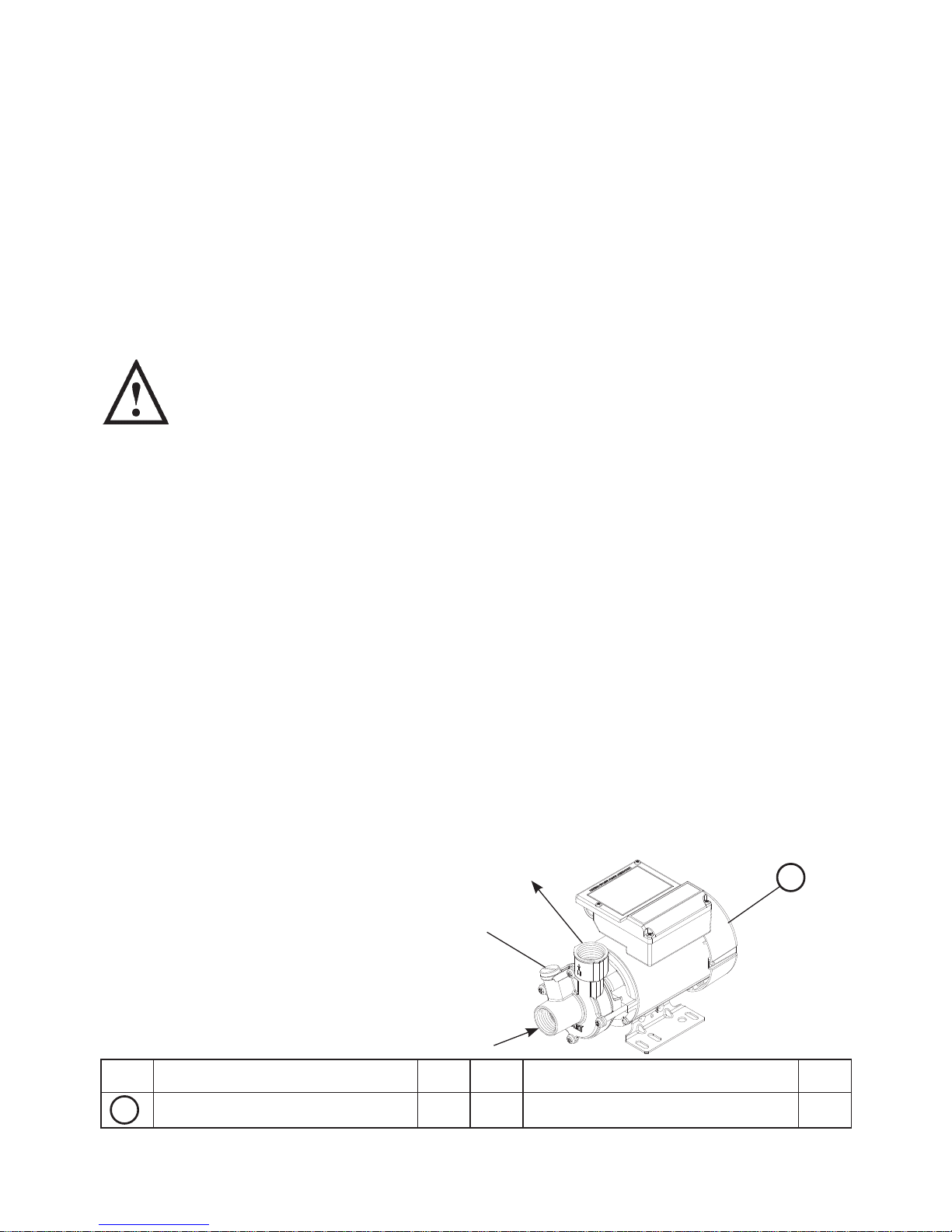
CHECKLIST
Your product may vary slightly from the picture above.
Item
Description Qty
Item
Description Qty
Pump 1
A
A
Fig. 1
G 1 Outlet
Priming
Plug
G 1 Inlet
IMPORTANT: With the pump
removed from its packaging
check for any damage prior to
installation. If any damage is
found contact Stuart Turner Ltd
within 24 hours of receipt.
Page 3
- 3 -
2.13 Fuses: The power cord must be sourced and supplied by the installer. Cable
selection and fuse size should be based on the motor full load current and the
surrounding conditions (supplied with 250 mm flying
lead for local requirements).
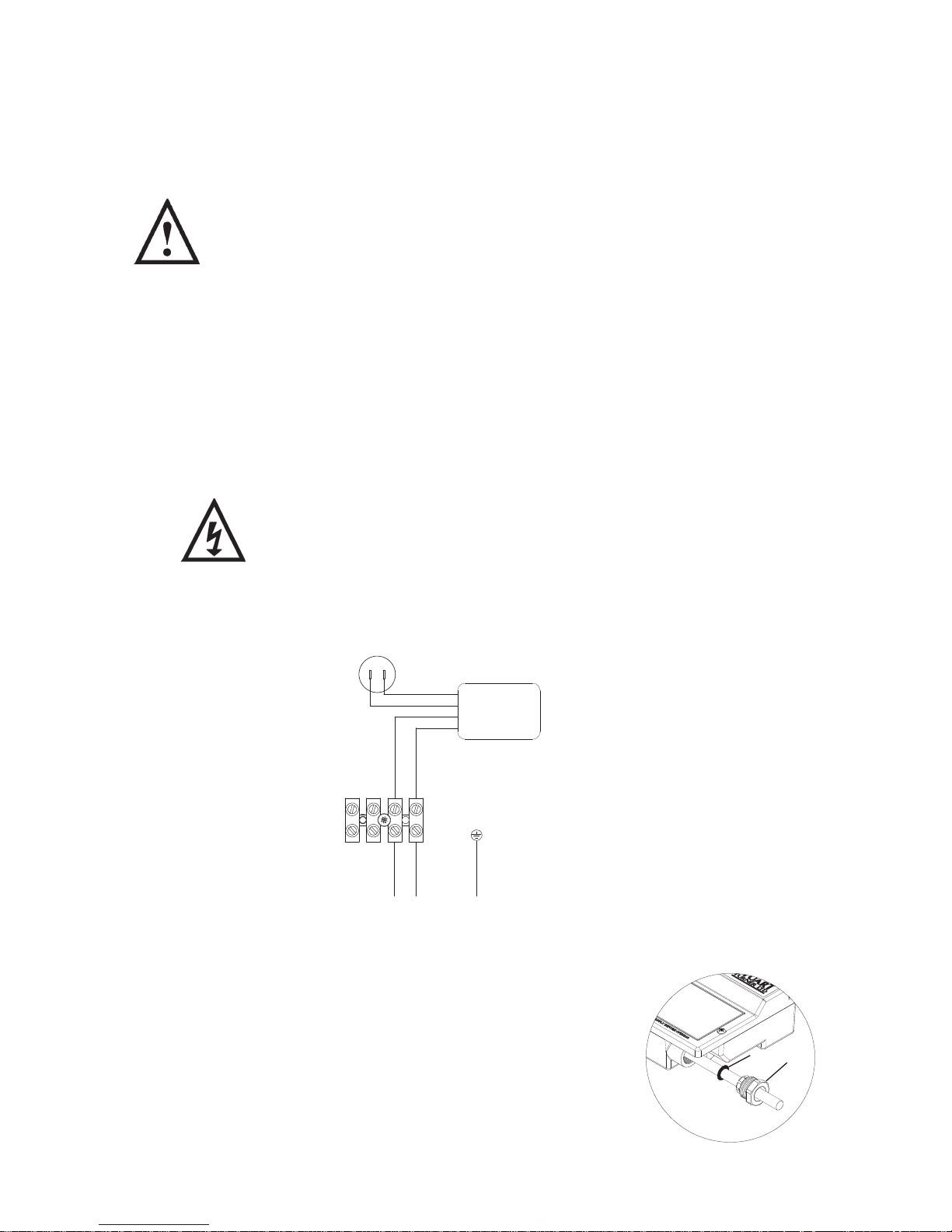
2.14 Cable Gland Fitting Instructions:
To enable correct assembly of the cable gland the
‘O’-ring (Fig. 3 item 1) must be placed over the cable
before the clamping insert (Fig. 3 item 2) can be
tightened.
Note: Cable diameter range:- 6.5 mm to 9.5 mm.
1 INSTALLATION
1.11 Secure pipework: Ensure pipework to and from pump is independently
supported & clipped to prevent forces being transferred to inlet and outlet
branches of pump.
1.12 DO NOT install a non-return valve, or devices which contain non-
return valves, in the suction (inlet) pipework to the pump. The pump
must be free to vent to the supply tank at all times.
1.13 DO NOT run against a closed valve for periods longer than 5 minutes.
1.14 DO NOT allow the supply cord to contact hot surfaces, including the
motor shell, pump body or pipework. The cod should be safely routed
and secured by cable clips.
1.15 Protection: The pump must be located in a dry position, frost free and protected
from freezing, particularly when installed in a loft (not recommended).
2 ELECTRICAL INSTALLATION
2.11 Wiring of connection unit:
WARNING: This appliance must be earthed.
The wires in the mains lead are coloured in accordance with the following code:
Green and Yellow: Earth Blue: Neutral Brown: Live
2.12 Wiring Diagram:
Fig. 3
2
1
230 VAC/1PH/50Hz SUPPLY
L N E
BROWN
BLUE
GREEN/YELLOW
RED
BLACK
CAPACITOR
MOTOR
RED
YELLOW
All models Fig. 2
Page 4

- 4 -
Cont ...
3 COMMISSIONING
3.11 Peripheral pumps should never be allowed to run dry. Before operating the
system, both pump and pipework should be primed. Further checks should
be made for leaks and when all is satisfactory the electrical supply to the pump
may be switched on. A vent/priming plug is fitted. To prime, release the vent plug
(see Fig. 1) until liquid emerges from the threads then re-tighten.
3.12 Safety: The motor casing can become very hot under normal operating
conditions, care should be taken to ensure it cannot be touched during operation.
3.13 Priming:
Never operate pump with inlet and/or outlet isolating valves in the
closed position. Damage will occur!
The pump must be primed (filled with water) before starting.
Turn on the service valves and vent/prime pump head.
(a) Loosen priming plug and allow an even flow of water this may take a
few seconds.
(b) Re-seal draining plug, nipping tight. The pump is now ready to start.
4 MAINTENANCE
4.11 No routine maintenance is required, but provision should be made for easy
access to the pump to allow for repairs due to normal wear and tear. Isolate the
pump from the electricity supply, turn off liquid supplies to the pump and release
pressure by opening liquid outlets before attempting repair.
4.12 Cleaners, Disinfectants and Descalents:
Acid based descalents and aggressive cleaning agents must not
come into contact with the pump. The pump must be removed from
the system prior to the use of these products. The system should be
flushed to remove all chemicals before the pump is re-connected.
If in any doubt as to the suitability of the chemical solutions, please
contact our Pump Assist helpline on 0844 98 000 97.
All models Fig. 4
Priming
Plug
Page 5

- 5 -
Cont ...
5 TECHNICAL SPECIFICATION
Stuart Turner reserve the right to amend the specification in line with its policy of
continuous development of its products.
*Note: Max working pressure is the maximum pressure that can be applied to
the pump internal casing under any installation conditions.
**Note: In normal circumstances the temperature of stored water should never
exceed 65 °C. A stored water temperature of 60°C is considered
sufficient to meet all normal requirements and will minimise deposition of
scale in hard water areas.
5.11 Noise: The equivalent continuous A-weighted sound pressure level at a distance
of 1 metre from the pump does not exceed 70 dB(A).
Model PH35 PH45
Electrical
Power supply
Volts/phase frequency
230/1/50 230/1/50
Enclosure IPX4 IPX4
Type of motor Induction Induction
Power consumption 380Watts 540 Watts
Full load current 1.6 Amps 2.4 Amps
Rating Continuous (S1) Continuous (S1)
Max. No Starts per hour 60 60
Mechanical
Min inlet head 1 metres 1 metres
Max inlet head 10 metres 10 metres
Max head (closed valve) 25 metres 42 metres
Max working pressure* 600 kPa (6.0 bar) 900 kPa (9.0 bar)
Max ambient air temperature 50
o
C 50 oC
Max water temperature** 80
o
C 80 oC
Min water temperature 4
o
C4
o
C
Cut in flow 1 l/min (approx) 1 l/min (approx)
Pump
Dimensions
Length (max) 241 mm 270 mm
Width (max) 130 mm 130 mm
Height (excluding flexible hoses) 167 mm 167 mm
Gross Weight (including accessories) 4.9 Kg 6.5 Kg
Pump Connections: Inlet G 1 Female G 1 Female
Outlet G 1 Female G 1 Female
Materials
Body Brass Brass
Shaft Stainless Steel Stainless Steel
Mechanical Seal Nitrile/carbon/ceramic Nitrile/carbon/ceramic
Page 6

- 6 -
6 YOUR 1 YEAR GUARANTEE
Stuart Pumps are guaranteed by Stuart Turner Limited to be free from defects in
materials or workmanship and the guarantee period starts from the date of purchase
or date of manufacture. Within the guarantee period we will repair, free of charge,
any defects in the pump resulting from faults in material or workmanship, repairing,
exchanging parts or exchanging the whole unit as we may reasonably decide.
Not covered by this guarantee: Damage arising from incorrect installation, improper
use, unauthorised repair, normal wear and tear and defects which have a negligible
effect on the value or operation of the pump.
Reasonable evidence must be supplied that the pump has been purchased within the
applicable guarantee period prior to the date of claim (such as proof of purchase or the
pump serial number).
In the event of a claim please telephone Stuart Turner Limited on 0844 980 0097
before taking any further action. If you have any doubt about removing a pump, please
consult a professional.
Proof of purchase should accompany the returned pump to avoid delay in investigation
and dealing with your claim.
Please record here for your records.
TYPE NO. SERIAL NO. DATE PURCHASED
Page 7

- 7 -
NOTES
Page 8

Stuart Turner Ltd, Henley-on-Thames, Oxfordshire RG9 2AD ENGLAND
Tel: +44 (0) 1491 572655, Fax: +44 (0) 1491 573704
email: pumps@stuart-turner.co.uk web: www.stuart-turner.co.uk
V.A.T. REG. No. 199 0987 92. Registered in England No. 88368. Registered Offi ce: Market Place, Henley-on-Thames
DECLARATION OF CONFORMITY
2006/42/EC
BS EN ISO 12100-1, BS EN ISO 12100-2, BS EN 809
2006/95/EC
BS EN 60335-1, BS EN 60335-2-41
2004/108/EC
BS EN 55014-1, BS EN 55014-2, BS EN 55022, BS EN 61000-3-2, BS EN 61000-3-3,
BS EN 61000-4-2, BS EN 61000-4-3, BS EN 61000-4-4, BS EN 61000-4-5, BS EN 61000-4-6,
BS EN 61000-4-11
1999/519/EC
BS EN 62233
2011/65/EU
IT IS HEREBY CERTIFIED THAT THE STUART ELECTRIC MOTOR DRIVEN PUMP AS
SERIAL NUMBER BELOW, COMPLIES WITH THE ESSENTIAL REQUIREMENTS OF THE
ABOVE E.E.C. DIRECTIVES.
RESPONSIBLE PERSON
AND MANUFACTURER STUART TURNER LIMITED
HENLEY-ON-THAMES, OXFORDSHIRE
RG9 2AD ENGLAND.
Signed . . . . . . . . . . . . . . . . . . . . . . . . . . . . . . . . . . . . . . . . .
Business Development Director
Stuart Turner are an approved company to BS EN ISO 9001:2000
Issue No. 4413/2-01 Pt. No. 19547
 Loading...