

STT Condigi CareCom IP, K1122 Installation Manual
CareCom IP
K1122
Installation Guide
STT Condigi
Agnesfridsvägen 113 A
212 37 Malmö
Sweden

2
Table of Contents
1 Introduction .............................................................................. 3
2 Installation ................................................................................. 4
2.1 Programming Mode..................................................................... 4
2.2 The Buttons Functions in Programming Mode .................. 4
2.3 Local Number ................................................................................. 4
2.4 Local IP .............................................................................................. 5
2.5 Server IP ........................................................................................... 5
2.6 ARM Flash/Edit Address/Set default EE ................................ 5
3 Mounting ................................................................................... 5
4 Power Supply and Connection to Network ......................... 6
4.1 Power Supply and Network Cable .......................................... 6
4.2 Connection ...................................................................................... 6
5 How to add a CareCom IP Room Unit to the
Swan CareCom System ............................................................ 7
5.1 Conguring 3CX Settings .......................................................... 7
5.2 Conguring the CareCom IP ..................................................... 8
5.3 Conguring the Equipment in the Swan CareCom
(TeleVagt) Data Base ........................................................................... 10
5.4 Conguring the ctCareComServer ......................................... 12
5.5 Conguring the ctDisplayServer ............................................. 13
3
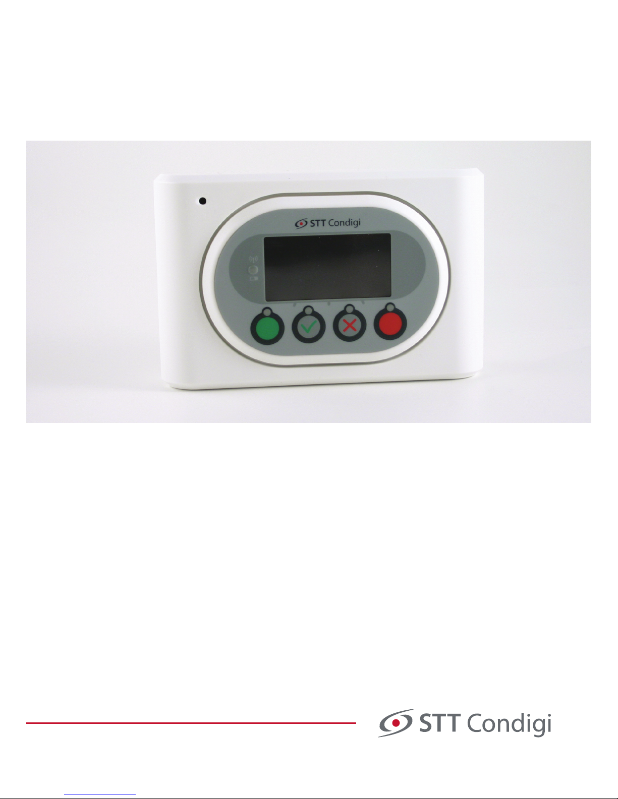
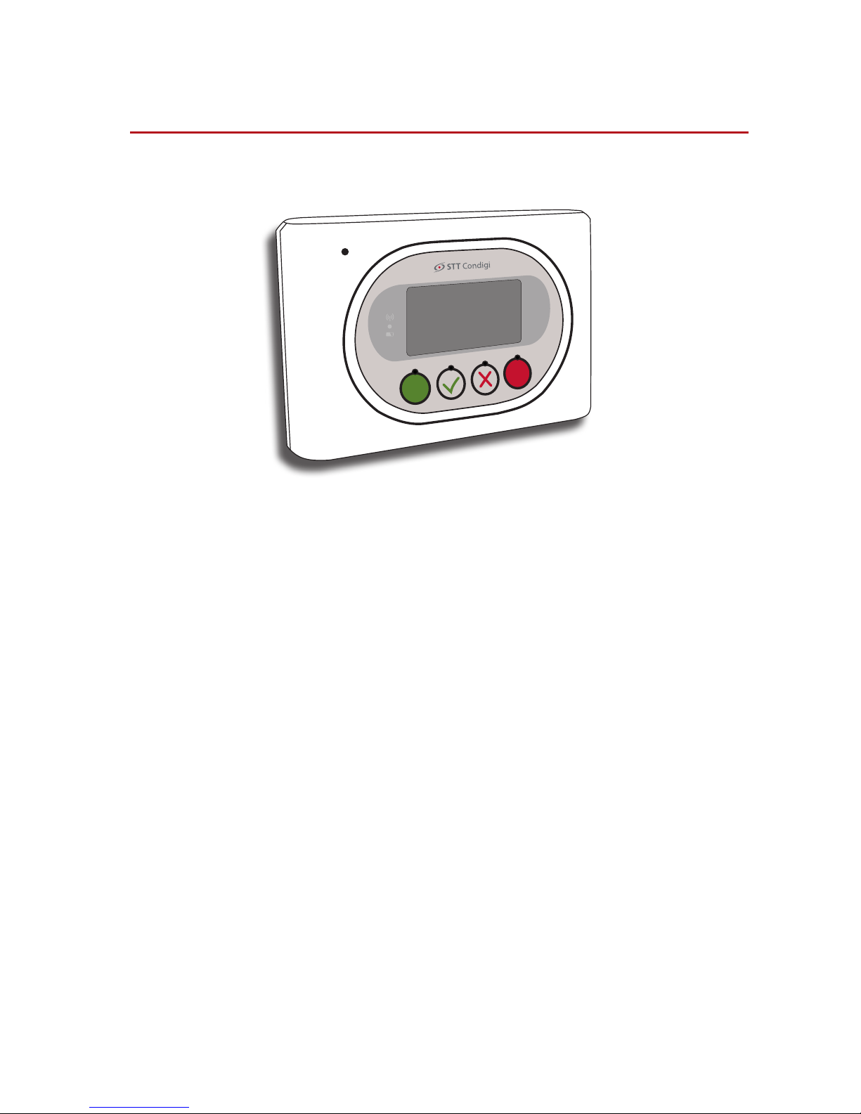
1 Introduction
CareCom IP is a room unit, which has speech (full duplex phone quality),
presence marking and alarm handling.
Furthermore, the CareCom IP has a display with the possibility to view
active alarms.
If viewing alarms is activated, it is possible to acknowledge the alarms
and to establish a 2-way conversation between the CareCom IP and the
device that has given the alarm.
CareCom IP is mounted on a wall and is connected to a POE switch/router.
Furthermore CareCom IP has two inputs and two outputs.
4
2 Installation
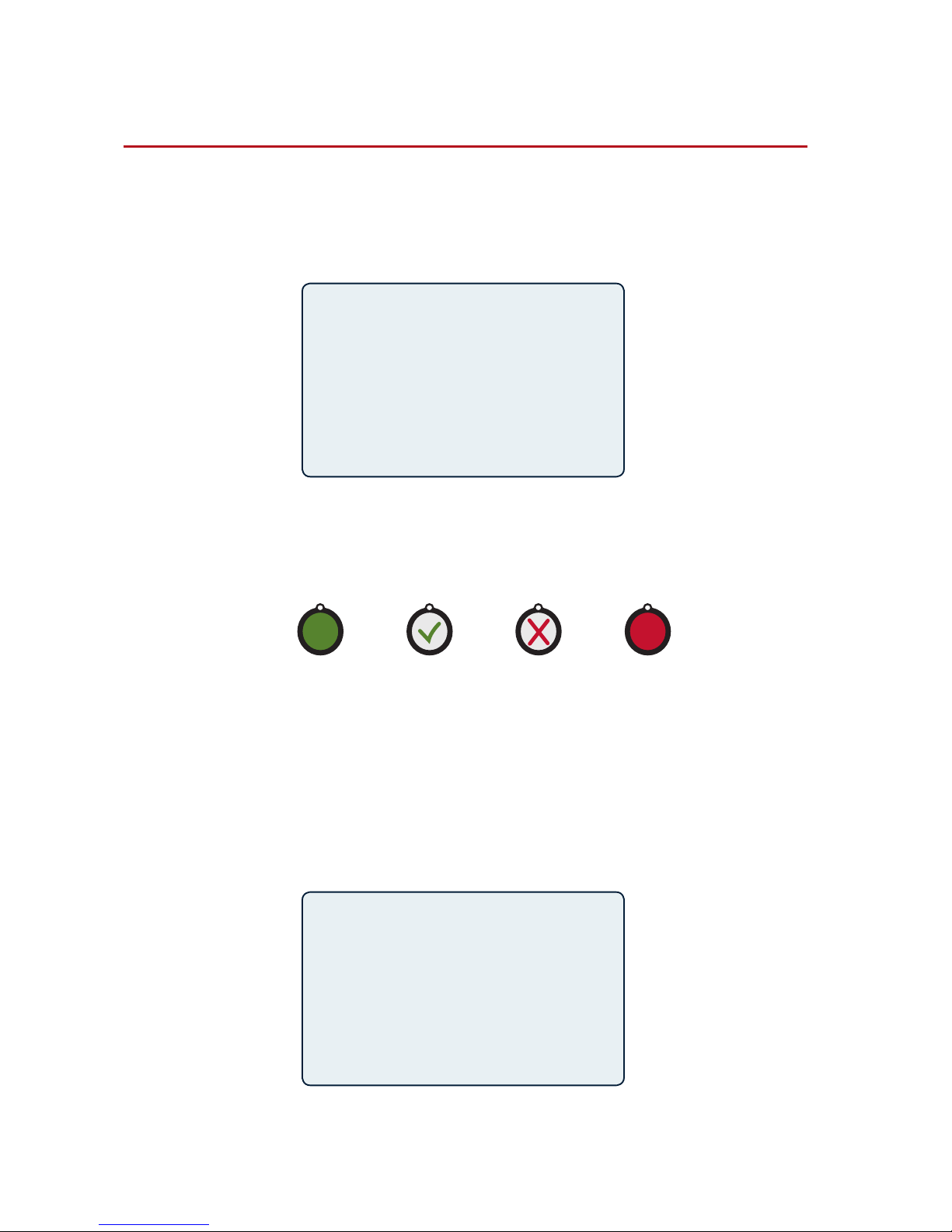
2.1 Programming Mode
Installation of CareCom IP is done in the programming mode, which is
accessed by holding down the red button while connecting the network cable. The display will then look like the illustration bellow.
>
Local Number
Local IP
Local Mask
Server IP
ARM Flash select
Edit Address
Set default EE
ESC UP DOWN ENT
>
Local Number
301_____________
–
ESC< + – >ENT
2.2 The Buttons Functions in Programming Mode
Below the display you will nd four buttons, which are used for programming. The four buttons are:
Escape/back Up Down Enter/forward
2.3 Local Number
Local number is set by selecting “Local Number”. Press “Enter” (red button)
when the check mark is next to “Local Number”. Press “+” (button with a
check mark) for higher numbers, “-” (button with a cross) for lower numbers and use the “ESC” and “ENT” to go forward or backward. Finally, press
several times on ENT until you exit the program and automatically saves
the setting.
5
2.4 Local IP
Local IP addresses is setup in the same way as a local number.
PLEASE NOTE: The local IP is the IP of the room unit. The room unit must be
connected to the network and may not conict with existing IP addresses.
See appendis and plan for IP addresses from page 10.
2.5 Server IP
Server IP is setup in the same way as a local number.
2.6 ARM Flash/Edit Address/Set default EE
These three functions are not used.
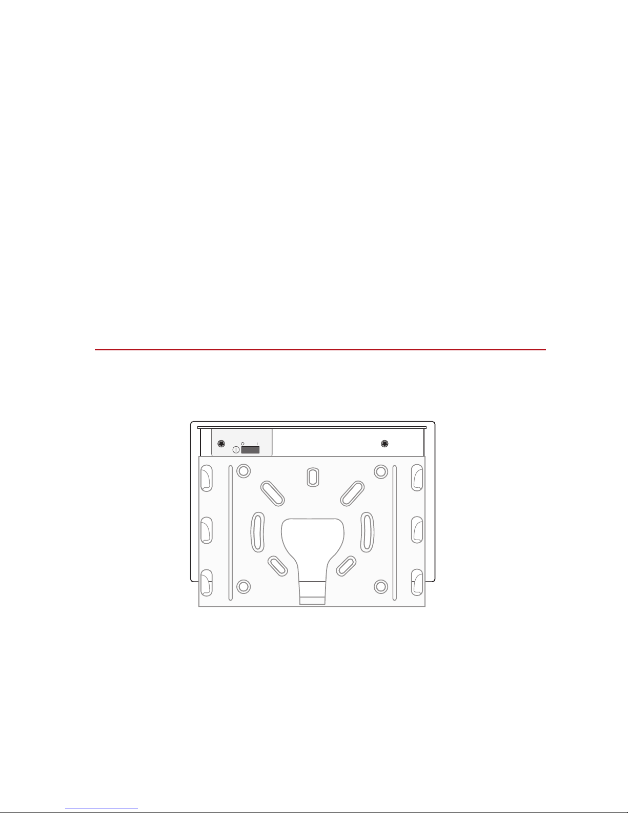
3 Mounting
CareCom IP is mounted on a wall – in the included wall bracket.
The illustration is viewed from the wall.
 Loading...