

STT Condigi Careline Anna, Careline GSM Programming And Installation Manual
Programming and installation manual Careline Anna / Careline GSM
Doc. no. 32-022-03-01 EN v6
Careline Anna /
Careline GSM
Programming and installation manual

Programming and installation manual Careline Anna / Careline GSM
Doc. no. 32-022-03-01 EN v6
List of contents
1 Introduction ........................................................................................................................................................ 3
1.1 General description of Careline Anna/GSM ..................................................................................................................................... 3
1.2 General description of Tx4 alarm transmitter ................................................................................................................................. 4
1.3 New functions of Careline Anna/GSM ................................................................................................................................................. 4
1.4 Buttons, Careline Anna/GSM ...................................................................................................................................................................... 5
1.5 LEDs .............................................................................................................................................................................................................................. 6
1.6 Battery ......................................................................................................................................................................................................................... 6
2 Installation ........................................................................................................................................................... 7
2.1 Programming......................................................................................................................................................................................................... 7
2.2 Connection to power supply ..................................................................................................................................................................... 7
2.3 Connection to the analogue telephone network ........................................................................................................................ 8
2.4 Connection to mobile network ................................................................................................................................................................ 8
2.5 Wall Mounting ...................................................................................................................................................................................................... 9
2.6 After Completed Installation ....................................................................................................................................................................... 9
3 Programming Structure ................................................................................................................................. 9
3.1 Table of Alarm Receiver Telephone Numbers ................................................................................................................................ 9
3.2 ...................................................................................................................................................10
3.3 Table for Alarm Types ....................................................................................................................................................................................10
3.4 Table for Sequences ........................................................................................................................................................................................11
4 Programming of the Hand Terminal ....................................................................................................... 11
4.1 Introduction to the Hand Terminal ......................................................................................................................................................11
4.2 Creating and Saving Programming in the Hand Terminal ..................................................................................................13
5 Programming of the carephone Careline Anna/GSM ...................................................................... 19
5.1 Programming of Careline Anna/GSM using the hand terminal ......................................................................................19
5.2 Programming via buttons on the top of the carephone ......................................................................................................21
6 Battery Replacement .................................................................................................................................... 23
6.1 Battery replacement for Careline Anna/GSM ................................................................................................................................23
6.2 Battery replacement for Tx4 ......................................................................................................................................................................24
7 Commands to the carephone ................................................................................................................... 25
7.1 Home phone ........................................................................................................................................................................................................25
8 Type of alarm ................................................................................................................................................... 26
8.1 Overview .................................................................................................................................................................................................................26
8.2 Explanation ............................................................................................................................................................................................................27
9 Description of menu selection in the hand terminal ........................................................................ 29
10 Appendix .......................................................................................................................................................... 38
10.1 Appendix A Specific information for your hand terminal .................................................................................................38
10.2 Appendix B Factory default values for the reset hand terminal ..................................................................................40
10.3 Appendix C Technical specifications for Careline Anna/GSM .......................................................................................44
10.4 Appendix D Technical specifications Tx4 alarm transmitter ..........................................................................................45
10.5 Appendix F Cable for input/output .................................................................................................................................................46
10.6 Appendix G WEEE Directive ..................................................................................................................................................................47
10.7 Appendix H Programming tree Careline Anna/GSM ..........................................................................................................48
Programming and installation manual Careline Anna / Careline GSM
Doc. no. 32-022-03-01 EN v6
1 Introduction
1.1 General description of Careline Anna/GSM
There are currently many types of telephony; therefore STT Condigi's new carephone comes in several models in
order to allow you to communicate in different ways. You can make an analogue emergency call or via GSM, or
calls can be sent as data traffic over IP or GPRS, this user manual describes the operation of the two analogue
models: Careline Anna and Careline GSM. The manual for the most part covers both models, but the part that
deals with GSM, of course, only applies to Careline GSM. When both models are referred to in the text it states,
Careline Anna/GSM.
Careline Anna and Careline GSM can transmit both speech and non-speech emergency alerts, to 10 different preprogrammed alarm recipients via the analogue telephone network and/or GSM network, and Careline GSM can
also send alerts to 8 different alarm recipients via GPRS. The alarm recipients then forward the alarm to, for
example, mobile phones, local wireless phones or an alarm centre, depending on the time and day. Dialling to the
various alarm recipients is done in a predetermined sequence, and may differ depending on the type of alarm.
The alarm activation is done by pressing the red button on the carephone or by pressing the red button on the
portable alarm transmitter. If the transmitter is used the alarm signal is transmitted to the carephone using a radio
signal. The carephone transmits the alarm to the pre-programmed alarm recipient. If it is a voice alarm, like the
normal medical alarms, the emergency operator can hold a conversation with the person who activated the
alarm. The carephone is equipped with both microphone and speaker and works as a speakerphone, which
allows calls with no additional push of a button from the user's side. Conversation can be held in a normal sized
apartment with good sound quality.
The carephone Careline Anna/GSM is connected to the telephone network by a cable. If the carephone has GSM
functionality it connects to the GSM network through a SIM card installed in the intended SIM card holder. For
power supply the supplied AC/DC transformer is connected. In the event of a power failure the carephone is
powered by the built-in accumulator (see section 1.6).
In addition to the alarm transmitter, Tx4 can connect additional radio transmitted alarm accessories, such as door,
IR or smoke alarms. Fixed-line alarms can be used through the STT Radiobox 869, T-box 869 or via the additional
card in the carephone (note that it requires a specific model of Careline Anna which has an extra socket for this
purpose.) In total, 16 radio-based devices can be connected at one time, including the Tx4, the portable alarm
transmitter, which is supplied with the carephone.
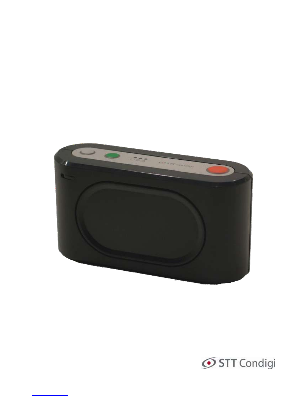
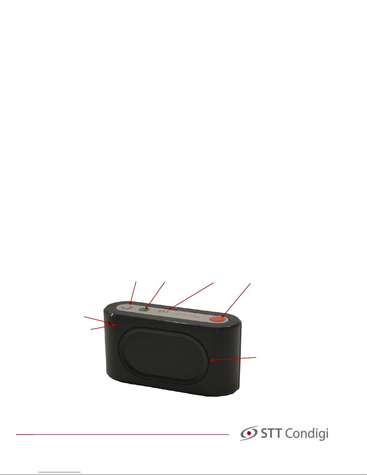
Image 1. Carephone Careline Anna/GSM
Grey Button
Present
Green Button
Reset
Red Button
Alarm
Microphone
Speaker
IR Receiver
LED Status
S

Programming and installation manual Careline Anna / Careline GSM
Doc. no. 32-022-03-01 EN v6
1.2 General description of Tx4 alarm transmitter
Alarms can be activated with the alarm transmitter Tx4. When the red button is pressed a red LED lights up on the
transmitter for a short period. When the alarm has been received by Careline Anna/GSM a signal is sent back to
the alarm transmitter to confirm that the alarm has been activated, then a green LED lights up briefly.
Tx4 uses dual frequency, which is a new feature that allows it to change frequency and transmit on another
frequency if there is a disruption on the primary frequency. When an alarm is activated Tx4 first broadcasts on
one frequency. If there is no response from the carephone the signal is repeated up to three times. After which,
the Tx4 changes frequency and transmits on the second frequency, up to four times. This feature provides
increased security and safety for the user. The radio frequencies used are the European-customised frequency for
social alarms 869.2125 MHz and 868.3000 MHz.
The Tx4 alarm transmitter can automatically send a link test to the carephone, which shows that the Tx4 is
working properly and has contact with the carephone. If the link test does not reach the carephone it will send
an alarm to a pre-programmed alarm recipient about the failure of the test alarm from the Tx. The function is
activated in the carephone with the help of the handterminal.
The alarm transmitter Tx4 is worn on a bracelet or necklace. The alarm transmitter is also waterproof (IP67) so that
the alarm transmitter can be worn during a bath or shower. A new feature of the Tx4 is that change of battery is
possible. See section 6.2.
1.3 New functions of Careline Anna/GSM
Careline Anna/GSM has many new features and options. A selection of them is listed below.
1.3.1 Dual frequency
Dual frequency allows Careline Anna/GSM to receive radio signals on two different frequencies 869.2125 MHz and
868.3000 MHz. Dual frequency provides extremely good security: if something were to disrupt the
communication on one frequency, the alarm can reach the carephone on the second frequency.
1.3.2 Greater amount of telephone numbers and sequences
In Careline Anna/GSM you can add 10 phone numbers and there are now 8 sequences. Each sequence can have
10 steps. Sequences can also be connected in series, so that when the carephone rings in accordance with one
sequence, it can continue to call in a different sequence. This provides great opportunities for extensive and
flexible programming.
1.3.3 GSM functionality
With the Careline GSM you have the ability to activate an alarm over the mobile network, which provides good
security if the analogue telephone network is down. For each telephone number you can choose if the
communication is to be made via telephone lines or wirelessly via the mobile network. You can also send an
alarm via GPRS. Therefore, you can also program internet addresses in the Careline GSM. You can set the APN you
wish to connect to, and the PIN of the SIM card, if a PIN is to be used.
1.3.4 Illumination of the alarm button
Something that has been requested is for the carephone's alarm button to be illuminated, so that it is easier to
find in the dark. This feature is a part of Careline Anna/GSM. Illumination of the alarm button can be turned on or
off, and you can also easily adjust the brightness to your liking.
1.3.5 Location code
Careline Anna/GSM has a new feature which means that a location code can be entered for each alarm
transmitter. Location codes are numbers that you can enter yourself for different places in the home, e.g., kitchen,
bedroom, hall. In this way it is possible, for example, to know which door alarm has been activated, the one
located at the main entrance or the patio door.

Programming and installation manual Careline Anna / Careline GSM
Doc. no. 32-022-03-01 EN v6
1.4 Buttons, Careline Anna/GSM
Careline Anna/GSM has three buttons on the top, all designed to be easy to push on. The buttons are:
Active Alarm (Red)
Reset (Green)
Present/Ready (Grey)
When you press the alarm button (or alarm transmitter) the carephone normally waits for 10 seconds before the
alarm is redirected. During this time, you hear an alarm signal and the alarm can be cancelled by pressing the
green button. Some alarms ring silently, for example, technical alerts such as test alarms and the battery alarm.
These cannot be cancelled with the green button.
If you wish a Present/Finish function can be activated so that the grey button on the carephone can be used to
register when staff are currently with the care recipient. (This is done via the hand terminal. The feature is found in
the menu, "Plus Alarm.") When the staff arrives to the care recipient, they notify this by pressing the grey button
on the carephone. When the button is pressed, the alarm signal and present indicator light up on top of the
carephone. When the staff is ready to leave the care recipient, the grey button is pressed again and a received
signal is heard. In this way, information on the length of stay can be collated in the system for each individual
care recipient.
1.4.1 Table of the button features
The table below describes the functions activated via buttons on the Careline Anna/GSM
Control Function
Press the red button in normal mode Alarm is activated
Press the red button when the phone is ringing
( 1)
The call is connected
Press green button during the call
( 1)
Dialling of the alarm is cancelled
Press the grey button in normal mode
(1)
Present/Ready signal
Hold the green button down, press the grey and red. Programming Mode
Release on audio signal.
Hold the green button down, press the grey and red. Restart
Release when the LEDs flash rapidly.
Hold the green button down, 2 press the red button
(1)
Present/Ready
Hold the green button and red button down for 3 s Manual, test alarm
Press green button down during start-up Activate function test
Hold red button down during start-up
(2)
Programming mode of radio transmitters
Press the grey button in the transmitter programming mode
(2)
Deprogramming of radio transmitter
Hold down the green button for three seconds
(2)
Away mode is activated/deactivated
1) Requires that the feature is enabled in the carephone.
2) See instructions in section 5.2.
For a description of the functions in the programming mode, see section 5.2
Programming and installation manual Careline Anna / Careline GSM
Doc. no. 32-022-03-01 EN v6
1.5 LEDs
On the top of the carephone there is a green light that indicates if the carephone has power, a yellow/orange
light indicates the function present and a red light to indicate if something is wrong. The following table
describes the LED signals and statuses.
Signal Status
Green fixed light Normal operation
Green flash (0. 5 s to / 4.5 s from) Battery power
Green flash (0.5 s to / 0.5 s from) Dialling
Green flash (1 s to / 1 s from) Waiting to call again
Green flash (2 s to / 2 s from) No more attempts
Green flash (70 ms to / 70 ms from) Starting GSM module
Yellow fixed light Staff present
Yellow flash Carephone set in away mode
Green and yellow flash (2 yellow flashes per green flash) Battery power and staff present
Green and yellow simultaneous flashing Battery power and off mode enabled
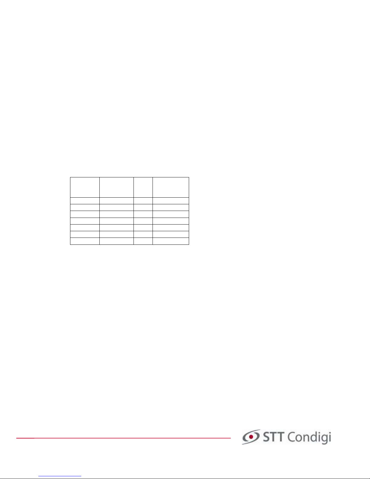
If the Warning System function is enabled, the LEDs provide additional information. The error that is indicated can
be found by counting the number of times the green LED flashes while the red LED is lit. The green LED flashes
are described in the table below.
Number of
flashes
Low Battery/
Charging
Mains
failure
No telephone
connection
1
No
No
Yes
2
No
Yes
No
3
No
Yes
Yes
4
Yes
No
No 5 Yes
No
Yes
6
Yes
Yes
No
7
Yes
Yes
Yes
1.6 Battery
In order for the carephone to function even when there is a mains loss (power cut), there is a rechargeable NiMH
battery in the carephone. The battery has a very long shelf life and the carephone sends a battery error when it
needs replacing. Charging the battery starts automatically when voltage returns. Careline Anna and Careline GSM
have different batteries. The standard battery in Careline Anna provides backup for about 100 hours. The
rechargeable battery, which is standard in Careline GSM is more powerful and gives backup for up to 420 hours.
Note! Only the battery supplied by STT Condigi may be used.
Programming and installation manual Careline Anna / Careline GSM
Doc. no. 32-022-03-01 EN v6
2 Installation
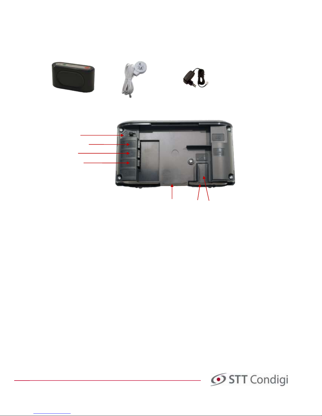
Everything that is needed for the installation is:
1 Carephone 1 Telephone adaptor with cable 1 Mains adaptor
Image 2. Placement of connectors, battery and SIM card.
2.1 Programming
The carephone must be programmed before it can be installed with the care recipient. To program the
carephone, follow the instructions in section 5.1.
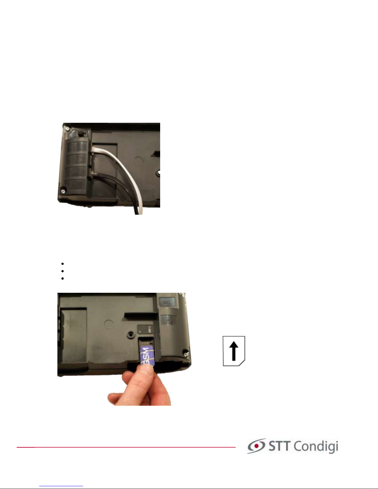
2.2 Connection to power supply
The mains adapter is plugged into an ordinary electrical socket and to the socket on the back of the carephone
marked 12V (see image 3 below). Then, turn on the switch (push button marked 0 / 1 to 1).
Note! Careline Anna/GSM may only be used with the supplied mains adapter.
Battery
On/Off (1/0)
Mains adaptor
Telephone
Telephone line in
Cable opening
SIM Card
Programming and installation manual Careline Anna / Careline GSM
Doc. no. 32-022-03-01 EN v6
2.3 Connection to the analogue telephone network
Connect the telephone cable into the supplied telephone adaptor and to the carephone in the socket closest to
the on/off button (see Image 3 below). The regular telephone plug should be connected to the supplied
telephone adaptor and then connected to the primary telephone socket at home.
Note!
It is important that the carephone is connected to the primary socket (the main socket) in the home in
order to achieve complete security! If you do not do this, your carephone may not be able to call the alarm
recipient, for example, if you have another phone in the home that is not on the receiver. To check which the
primary socket is, lift all the handsets off the receivers in the home. The handset which still has a dial tone is the
primary. If more than one handset has the dialling tone at the same time, the phone socket is not connected
properly and must be adjusted by an authorised installer.
Image 3. Here you can see in which jack the telephone cable (white) and mains adapter (black) are to be
connected.
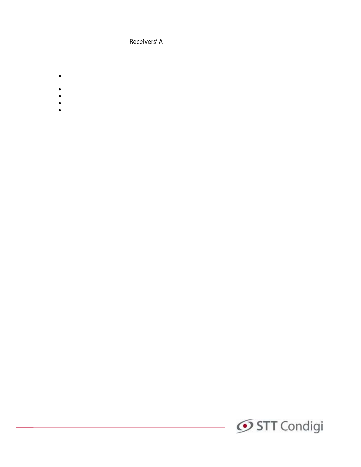
2.4 Connection to mobile network
To insert a SIM card in Careline GSM:
Loosen the screw to the battery cover and pull it out.
Slide the SIM card into the holder as shown in image 4 below.
Slide the battery cover back in place (hold the SIM card if it does not slide easily) and attach the cover with
the screw.
Image 4. Slide the SIM card into the SIM card holder.

Programming and installation manual Careline Anna / Careline GSM
Doc. no. 32-022-03-01 EN v6
2.5 Wall Mounting
If the carephone is to be mounted on the wall, you can choose which way it should be mounted. Then press out
the cover for the selected holes. The distance between holes is about 110 mm and 42 mm. It can be beneficial to
use the back cover of the carephone as a template when you mark where to place the screws. Use screws with
heads that fit the holes so that the carephone can easily be hung up and lifted off when necessary.
2.6 After Completed Installation
After the basic programming, installation and programming of the alarm transmitter has been completed, carry
out a function test.
Carry out a range test (see instructions in Section 5.2.5)
Try to send an alarm. If the alarm is to go via the analogue telephone line
and
via GSM - be sure to try both.
Note!
The back cover of the carephone should be on to ensure the best sound quality!
3 Programming Structure
This section helps you to structure the values to be inserted into the hand terminal, which is then used to
program the carephone. Read through it and then fill in the corresponding tables in Appendix A at the end of this
manual. The completed tables facilitate the programming of the hand terminal.
3.1 Table of Alarm Receiver Telephone Numbers
In order for Careline Anna/GSM to transfer an alarm to an alarm recipient via an analogue telephone line or GSM
connection, it is necessary to program it with the following information:
Phone number to the alarm receiver (or receivers if there are more than one)
Protocol, i.e., which transfer method is to be used, such as STT, CPC, etc.
Alarm code that tells the alarm receiver from which carephone the alarm has been sent
Number of attempts the carephone shall make to the different alarm telephone numbers.
If the communication is to go via analogue or via GSM.
When the user programming has been completed, it may look like the table below. Fill in the values of your
programming in the table in Appendix A.
Number Telephone no. Protocol Alarm code ¹ No of attempts Connection²
A 0406252500 STT 1234 3 Telephone line
B 0406252500 STT 1234 3 Wireless
C 0406252550 STT 1234 3 Telephone line
D 020223242 STT 111234 5 Wireless
E - - - - F - - - - G - - - - H - - - - I - - - - J - - - - N (Nightmode) 020223242 STT 123456 5 Wireless
V (Forwarding) - - - - -
1) The alarm codes need only be entered if the alarm is to be sent with different alarm codes to the various
alarm receivers.
2) Only available if the carephone has GSM functionality.
Note!
Note that if you want to call the same number first over the telephone line and then wireless via GSM (or
vice versa) you must enter this number twice (see code A and code B) and specify the different connection types.
Programming and installation manual Careline Anna / Careline GSM
Doc. no. 32-022-03-01 EN v6
3.2 Table of Alarm ddresses
A major innovation in Careline GSM is the ability to communicate over GPRS. For the carephone to transfer an
alarm to an alarm receiver via GPRS it is necessary to program it with the following information (this table is
therefore only applicable if the carephone has GSM functionality).
Internet address to an alarm receiver (or receivers if there are more than one) and port, separated by
semicolons. Internet address can be entered both as text and as a numeric IP address.
Protocol, i.e., which transfer method is to be used, STT IPACS is standard.
Alarm code that tells the alarm recipient from which carephone the alarm has been sent
Number of calls the carephone shall make to the different alarm telephone numbers.
As Careline GSM does not have a fixed IP connection all communication to the IP addresses is wireless.
When the user programming has been completed, it may look like the table below. Fill in the values of your
programming in the table in Appendix A.
No Address Protocol Alarm code¹ No of attempts Connection
a 111.10.35.45:10000 STT IPACS 1234 3 Wireless
b 222.20.35.45:10000 STT IPACS 1234 3 Wireless
c 333.30.35.46:10000 STT IPACS 1234 3 Wireless
d 444.40.38.48:10000 STT IPACS 111234 5 Wireless
e - - - - f - - - - g - - - - h - - - - n (Nightmode) 555.50.35.45:10000 STT IPACS 123456 5 Wireless
v (Forwarding) - - - - -
3.3 Table for Alarm Types
The types of alarms that are activated in the carephone, both the automatic and the manual, can be sent to
different alarm receivers or be handled in a different manner depending on the type of alarm. For example, you
can choose to deal differently with technical alarms than alarms activated by the care recipient, such as medical
alarms. The table below shows a configuration example.
Please note that Plus Alarm and Test Alarm can now be configured to run in different sequences and that the
bedside alarm, carpet alarm and door alarm now have their own sequence, and are no longer sent in the same
wayas a Passive Alarm.
Fill in the values of your programming in the table in Appendix A.
Type of alarm Sequence
Medical alarm Sequence 1
Passive Alarm Sequence 1
Acc. /Mains Sequence 2
Fire Sequence 1
Person protect Sequence 3
Extended Sequence 2
Emerg./Remind. Sequence 1
Assistance Sequence 1
User defined Sequence 1
Test Alarm Sequence 2
Bed/Carpet/Door Sequence 1
Programming and installation manual Careline Anna / Careline GSM
Doc. no. 32-022-03-01 EN v6
3.4 Table for Sequences
When an alarm receiver does not respond to the call, the carephone can continue to call another alarm receiver.
The table contains information about in which sequence the carephone shall contact the programmed phone
numbers/addresses. This can vary between different alarm types (see Section 4.2.5). The Careline Anna/GSM has
increased both the number of sequences and the number of steps in each sequence. Now you can enter as many
as 8 sequences with 10 steps in each sequence.
Cascading means that the carephone can continue to call with a different sequence if it does not get an answer
on any of the attempts in the first sequence.
When the programming has been completed, it may look like the table below. Note that the secondary number
or address you choose to contact is not necessarily called by the carephone on the second attempt; it depends
on how many calls have been entered for the respective number/address (see Section 4.2.2 and 4.2.3). The
number listed in "Repeat sequence" is the number of times that the sequence is repeated, if the alarm does not
get answered. If the value 1 is set, it means that the sequence is run once. If the value 2 is specified, it means that
the sequence is run once and then repeated once. In the sequences the phone numbers are represented by
upper-case letters and the addresses by lower-case.
Fill in the values of your programming in the table in Appendix A.
1st 2nd 3rd 4th 5th 6th 7th 8th 9th 10th Cascading
Sequence 1 A B A B - - - - - - Sequence 2
Sequence 2 a b c a b c - - - - -
Sequence 3 C C C C c c c c - - Sequence 4
Sequence 4 D d D d e - - - - - Sequence 5 - - - - - - - - - - Sequence 6 - - - - - - - - - - Sequence 7 - - - - - - - - - - Sequence 8 - - - - - - - - - - -
Repetition of Sequence 2
4 Programming of the Hand Terminal
4.1 Introduction to the Hand Terminal
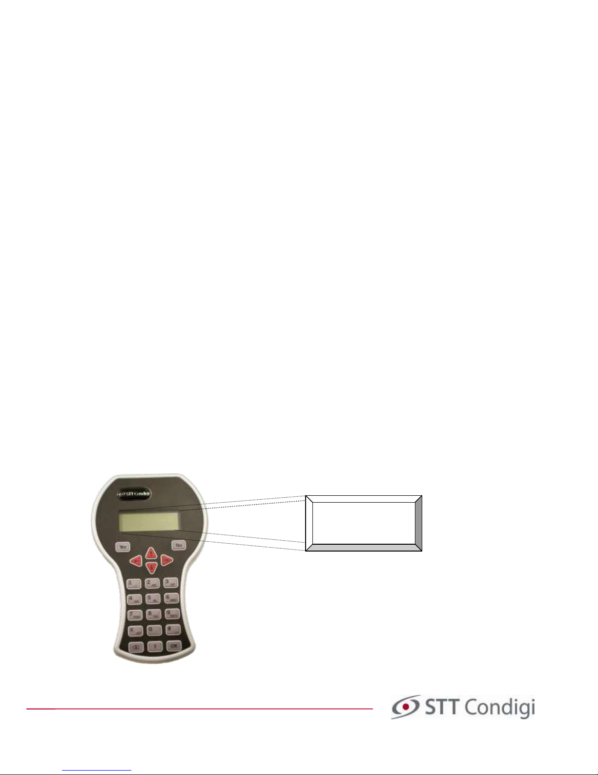
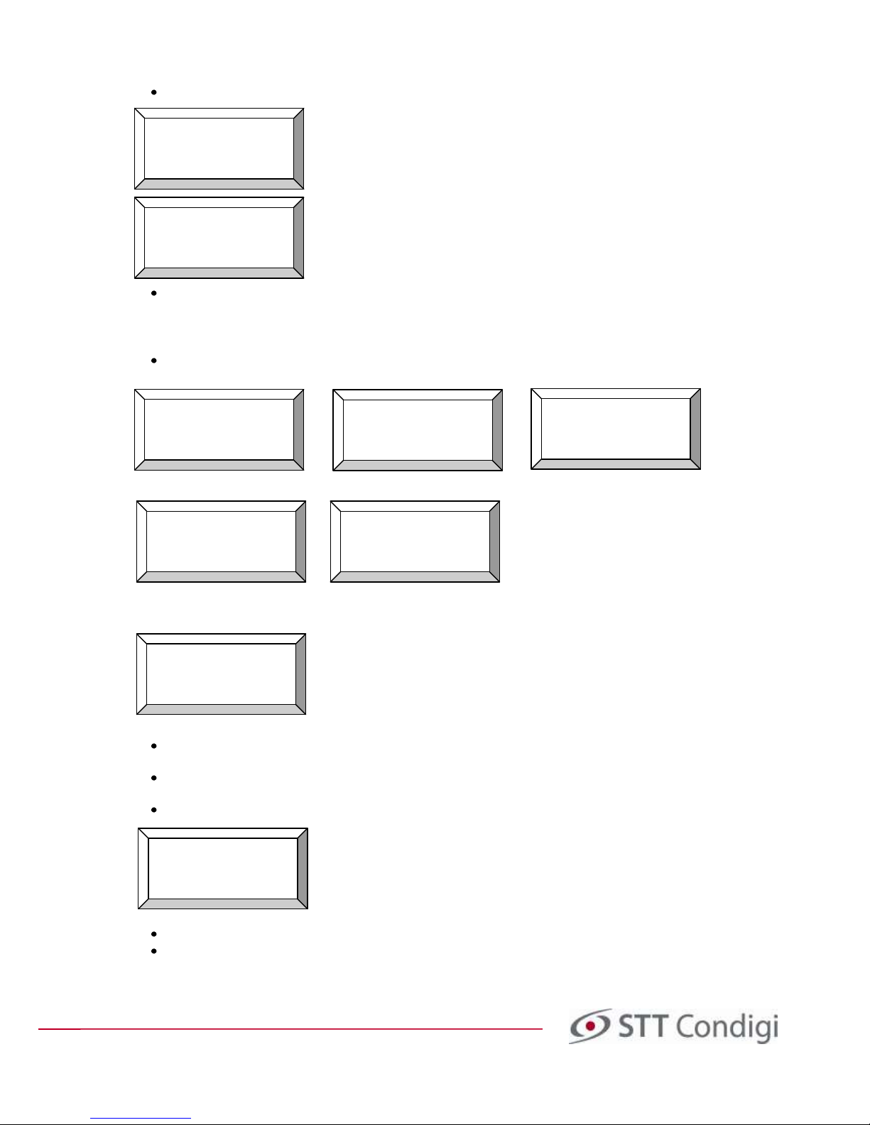
The carephone is programmed using a HT-III Hand terminal (see image 5), which connects to the back of the
carephone using the supplied red wire.
The text in the display will be shown
like this in the rest of the document.
Image 5. Hand terminal HT-III with a 4-row display and buttons
Connect
carephone
or press
for offline
Programming and installation manual Careline Anna / Careline GSM
Doc. no. 32-022-03-01 EN v6
The Hand terminal has a display on the top. The display shows the different lines of text that guide the user
through programming. Below the display there are buttons for the digits 0-9 and letters A-Z as well as symbols
such as Yes, No, , *, #, , T and OK.
4.1.1 General Functions of the Hand Terminal
Control Function
Yes, OK Accept the entered value or go forward in the menu
No Leave the current menu level, and ignore entered value
Up in the menu
Down in the menu
Back one symbol
Forward one symbol
T Enter 'wait for dial tone' in the phone number or activate the receiving of the radio code from the
alarm transmitter
Delete the symbol to the left of the cursor
Careline Anna/GSM can be programmed to wait 500 ms before the phone is switched. Use -button when you
enter the phone number to enter a W.
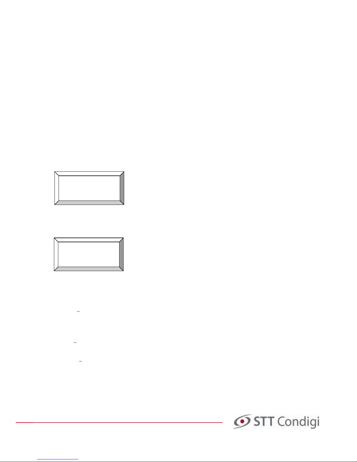
The display of the hand terminal shows four rows such as:
There can be more rows in the menu that are not displayed. To switch between the different choices in the menu
use and on the hand terminal. The current choice is marked with > and <. If, for example, you want to switch
from A to C, press the button twice on the hand terminal.
4.1.2 Memory in the Hand Terminal
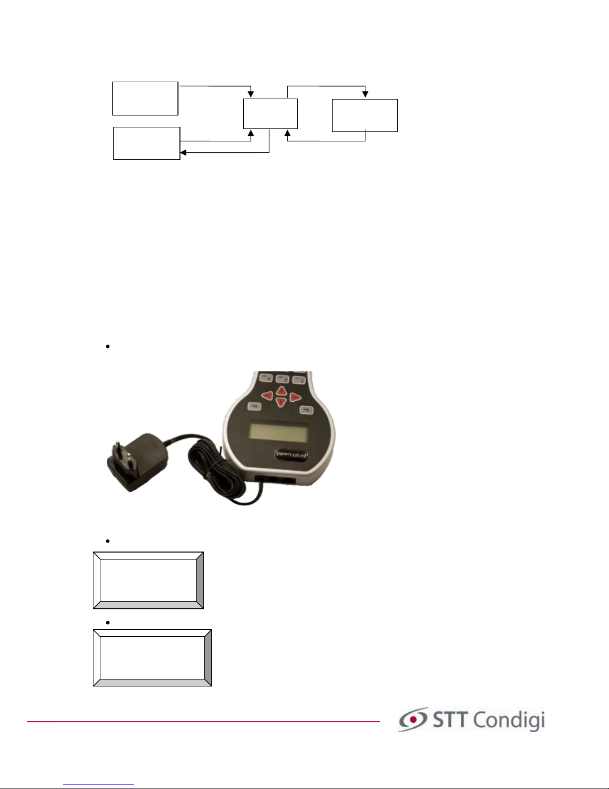
The Hand terminal has three different types of memory, where data is stored. The different memory functions are
described here, and image 6 below shows how data is transferred between them.
Work area
Contains the values that you work with when using the hand terminal. You can obtain value from the
carephone, or reset the area or any preset parts of the work area. The values that are applicable in the work area
are the ones sent to the carephone.
Note! If you make changes to the work area, but then quit the program
without saving these values in the preset area, they will be gone the next time you connect the hand terminal.
The area
This area always has a basic setting which is standard for all the hand terminals and non-programmed
carephones and as you can see in the image you can never change the data in the reset area.
Preset area
In the preset area you can find the data saved by yourself in the Hand terminal. When you start the
Hand terminal the values are retrieved from the preset area 1. Each model of the carephone has seven own preset
areas where you can save different settings.
PHONE NUMBERS
Number A
Number B
>Number C <
PHONE NUMBERS
>Number A <
Number B
Number C
Programming and installation manual Careline Anna / Careline GSM
Doc. no. 32-022-03-01 EN v6
Image 6. Data flow between the memory areas in the handterminal and the carephone.
4.2 Creating and Saving Programming in the Hand Terminal
Follow these instructions step-by-step to program the default values that you want to program the carephone
with, and save these in the preset area. All the values that are common for all carephones should be here. This
saves you entering them each time you program a carephone, you can simply enter the values specific to this
carephone (usually only the alarm code) and then transfer it with the default values you previously saved in the
hand terminal to the carephone. Use the completed tables in appendix A to facilitate programming.
Note!
This section gives you a good basic programming, but the carephone offers many more possibilities than
these! Please read section 8 in which almost all the features found in Careline Anna/GSM are described.
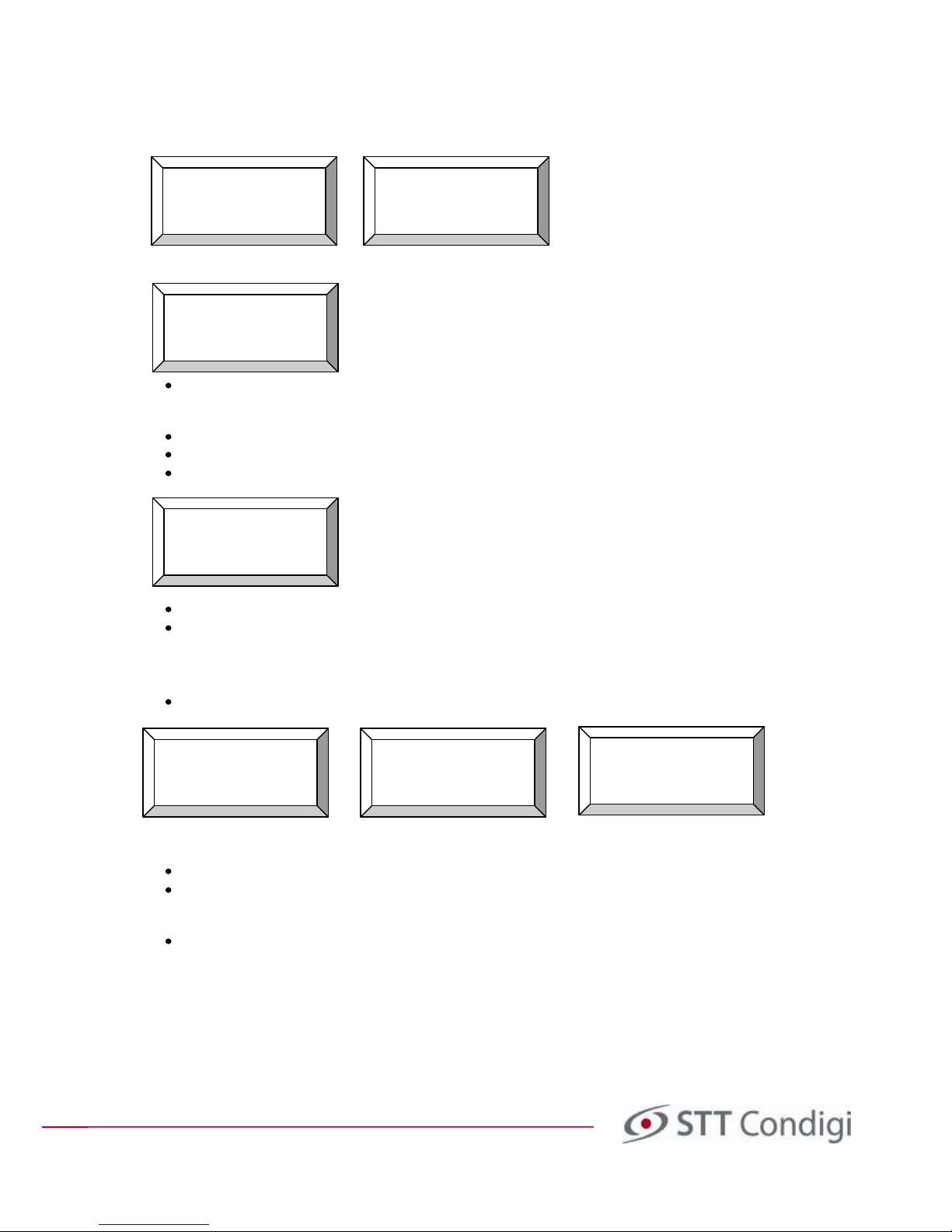
4.2.1 Connect the Hand Terminal
Connect the mains adapter to the hand terminal's smallest outlet (see image 7 below) and to a standard
electrical socket.
Image 7. Connect the Hand terminal's smallest outlet, as per the image above.
The display of the hand terminal shows the following:
Press on the hand terminal. The display will show:
Connect to the
carephone
or press
to stand alone
Arbets-
area
Reset Area
Preset Area
Load std. values
Save to preset
menu selection
Upload on
start up
Carephone
Load from TT
Send changes
Working
Area
DEVICE TYPE
>Careline GSM <
Careline Anna
Reflex Plus II
Programming and installation manual Careline Anna / Careline GSM
Doc. no. 32-022-03-01 EN v6
Choose the model you want to program by pressing and and then press Yes.
Go to the next step: programming of the telephone number
4.2.2 Programming of the telephone number of the alarm receiver
If an alarm is to ring via the analogue telephone network or via GSM, the telephone number must be
entered. In that case, continue with the programming as follows:
Choose Programming, press Yes Enter code 1812 Choose Programming, and press Yes
Choose Phone numbers, press Yes. Choose Phoneno. A, press Yes
Enter the phone number from the alarm number table in Appendix A. Write the numbers in sequence
without a hyphen. To delete numbers if you accidentally press wrong, press.
If you have to enter a 0 to access an outside line, enter 0 and then T before entering the usual number, for
example, "0T040123456". T stands for Tone (Connection Tone).
Finish by pressing Yes.
Press for the next number and repeat the procedure above to add the telephone numbers B, C etc.
Press No to exit the menu "Phone numbers".
Terminal VX.YSE
connects
Careline GSM
MAIN MENU VX.YSE
>Edit alarm code <
Speaker vol.
Quit
Edit alarm code
Speaker vol.
Quit
>Programming < <
Enter password:
- - - -
PROGRAMMING
>Program <
Load from phone
Load std.values
PROGRAM
>Phone numbers <
Addresses
Transmitters
PHONE NUMBERS
>Phoneno. A <
Phoneno. B
Phoneno. C
Value in HT:
<not programmed>
New Value:
XXX…
Value in HT:
<not programmed>
New value:
0T040123456
Programming and installation manual Careline Anna / Careline GSM
Doc. no. 32-022-03-01 EN v6
4.2.3 Programming of the address of the alarm recipient
If the carephone is the Careline GSM model, the alarm can be sent via GPRS. The Internet addresses of the alarm
receivers shall be entered, according to the instructions below:
Choose Addresses, press Yes. Choose Address A, press Yes
Enter the Internet address and port from the address table in Appendix A (may be in letters or numeric IP
address). Any symbols you may need are on the buttons 1 and 0. To switch between upper-case and
lower-case letters, press the *- button.
Maximum 48 characters (16 in each row).
To delete if you accidentally press wrong, press .
Finish by pressing Yes.
Pressto the next address and repeat the procedure above to add the addresses B, C etc.
Press No to exit the menu "Addresses".
4.2.4 Programming of protocol
When sections 4.2.2 and/or 4.2.3 are finished, continue according to the below:
Choose Protocol, press Yes Choose Protocol A, press Yes Value STT has been acquired
Press or until the protocol is shown in the "new value" field and press Yes to accept.
Repeat the procedure for Protocol B, C etc. For each phone number entered in section 4.2.2, a protocol must
be specified. The protocol for the addresses are below the protocols for telephone numbers, but there is
the protocol STT IPACS default.
Press No to exit the menu "Protocol".
Alarm types
Location codes
Alarm codes
>Protocol <
PROTOCOL
>Protocol A <
Protocol B
Protocol C
Value in HT:
<STT>
New Value:
<STT>
PROGRAM
Phone numbers
>Addresses <
Transmitters
ADDRESSES
>Address a <
Address b
Address c
Value in HT:
Value in HT:
111.10.35.45:100
00
 Loading...