

Page 1
DRAFT
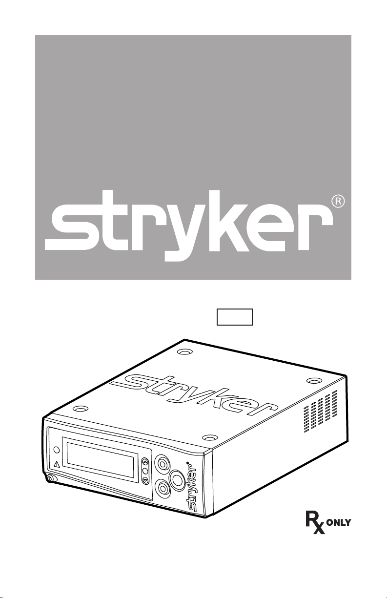
Crossfire™ 2
REF 0475100000
Page 2

Page 3

Contents
Warnings and Cautions .....................................................................3
Product Description/Intended Use ................................................ 7
Package Contents ................................................................................ 8
Available Accessories ........................................................................... 8
The Crossre2 Console ........................................................................9
The Crossre2 Interface ..................................................................... 11
Arthroscopy Mode ............................................................................12
Indications for Arthroscopic Use .........................................................12
Setup and Device Connections ........................................................... 13
Adjusting User and System Settings ....................................................17
Arthroscopic Shaver Controls ..............................................................19
RF Ablation Controls ..........................................................................25
Dual Controls .....................................................................................30
Laparoscopy Mode ...........................................................................32
Indications for Laparoscopic and General Surgery Use .........................32
Setup and Device Connections ........................................................... 33
Adjusting User and System Settings .................................................... 36
Vessel Sealing Controls .......................................................................38
Troubleshooting................................................................................44
Error Codes ........................................................................................46
Cleaning and Maintenance ............................................................47
Cleaning ............................................................................................47
Maintenance......................................................................................47
Disposal ............................................................................................48
Technical Specications .................................................................. 49
Generator Output ..............................................................................50
Electromagnetic Compatibility ...........................................................55
Symbol Glossary ................................................................................59
EN-1
Page 4

Page 5

Warnings and Cautions
Please read this manual and follow its instructions carefully. The words
warning, caution, and note carry special meanings and should be carefully
reviewed:
Warning Warnings indicate risks to the safety of the patient or user.
Failure to follow warnings may result in injury to the patient
or user.
Caution Cautions indicate risks to the equipment. Failure to follow
cautions may result in product damage.
Note Notes provide special information to clarify instructions or
present additional useful information.
DRAFT
To avoid potential serious injury to the user and the patient and/or
damage to this device, the user must obey the following warnings. The
warranty is void if any of these warnings is disregarded.
1. Caution: Federal law (USA) restricts this device to use by, or on order of, a
physician.
2. Attempt no internal repairs or adjustments not specically detailed in this
operating manual. Refer any readjustments, modications, and/or repairs
to Stryker Endoscopy or its authorized representatives.
3. Pay close attention to the care and cleaning instructions in this manual.
Failure to follow these instructions may result in product damage.
4. Install this device in an operating room that complies with all applicable
IEC, CEC, and NEC requirements for safety of electrical devices.
5. DO NOT use the Crossre2 system on patients with cardiac
pacemakers or other electronic device implants. Doing so could lead to
electromagnetic interference and possible death.
Fire/Explosion Warnings
1. DO NOT use this device in the presence of ammable anaesthetics, other
ammable gases or objects, near ammable uids such as skin prepping
agents and tinctures, or oxidizing agents. Observe appropriate re
precautions at all times.
2. DO NOT use this device in oxygen-enriched atmospheres, nitrous oxide
(N₂O) atmospheres, or in the presence of other oxidizing agents, to
prevent risk of explosion. Ensure that oxygen connections are not leaking.
EN-3
Page 6

3. Electrosurgical components, such as the probe, may remain hot following
activation. Keep all electrosurgical equipment away from ammable
materials to avoid combustion.
4. To prevent the risk of re, DO NOT replace console fuses. If it is
suspected that fuses are damaged, return console to Stryker for repair.
Prior to Surgery
1. The operator of the Crossre2 system should be a qualied physician,
having complete knowledge of the use of this equipment and awareness
of the risks associated with arthroscopic and laparoscopic electrosurgical
procedures.
2. The operator of the Crossre2 system should be experienced in
arthroscopic and electrosurgical practices and techniques.
3. The operator of the Crossre2 system should read this manual
thoroughly and be familiar with its contents prior to operating the
equipment.
4. The operator of the Crossre2 system should be sure that the system
functions as outlined in this manual prior to a surgical procedure. The
Crossre2 system was fully tested at the factory before shipment.
5. Crossre2 system components are designed to be used together as a
system. Use only the appropriate footswitch, handpiece, and disposable
attachments described in this manual.
6. Carefully unpack the unit and ensure that all components are accounted
for and remain undamaged from shipment. Inspect the handpiece cable
for any damage to insulation. If damage to any component is detected,
refer to the “Service and Claims” section of this manual.
7. Ensure the proper connection of the primary power cord of the
Crossre2 System to a grounded receptacle. To prevent risk of electric
shock DO NOT use extension cords or adapter plugs.
8. DO NOT wrap the handpiece cable around metal objects, or the induction
of hazardous currents may result.
9. Position the cables to avoid contact with the patient, electrodes, cables,
and any other electrical leads which provide paths for high frequency
current.
10. Position the console so the fan directs the ow of air away from the
patient.
11. When the Crossre2 system and physiological monitoring equipment
are used simultaneously on a patient, position any monitoring electrodes
as far as possible from the surgical electrodes. Monitoring equipment
using high frequency, current-limiting devices is recommended. Needle
DRAFT
EN-4
Page 7

monitoring electrodes are NOT recommended.
12. Smoke generated during electrosurgical procedures may be harmful to
surgical personnel. Take appropriate precautions by wearing surgical
masks or other means of protection.
During Surgery
1. DO NOT use the Crossre2 system with non-conductive irrigants (e.g.
sterile water, air, gas, glycine, etc.). Use only conductive irrigants such as
saline or Ringer’s lactate in order for the system to function properly.
2. DO NOT allow the patient to come into contact with grounded metal
objects or objects that have an appreciable capacitance to the earth, such
as a surgical table frame or instrument table, to prevent risk of shock. The
use of antistatic sheeting is recommended for this purpose.
3. DO NOT activate the Crossre2 system for prolonged lengths of time
when the attachment is not in contact with tissue. Doing so may lead to
unintentional damage to surrounding tissue.
4. When the Crossre2 system is activated, the conducted and radiated
electrical elds may interfere with other electrical medical equipment.
Provide as much possible distance between the console and other
electronic medical equipment.
5. Select the lowest output power required to prevent patient injury.
6. Maintain the active electrode in the eld of view at all times to avoid
tissue damage.
7. Remove the handpiece and disposable attachments from the surgical site
and place them away from metallic objects when not in use. Attachments
should be separated from other electrosurgical equipment to avoid
inadvertent electrical coupling between devices. Inadvertent activation
may cause user/patient injury and/or product damage.
8. Keep the ends of the handpiece cable connectors, footswitch cable
connectors, and console receptacles away from all uids.
9. DO NOT activate the Crossre2 system until the probe is properly
positioned in the patient.
10. Ensure that the probe tip, including the return electrode, is completely
surrounded by irrigant solution during use.
11. Keep the activation indication lights and speaker in eld of view and
hearing at all times during activation. The light and sound are important
safety features.
12. DO NOT touch the attachment to metal objects, such as an endoscope
or metal cannula, while activating the handpiece. Damage to the
attachments or other devices may result.
DRAFT
EN-5
Page 8

13. DO NOT obstruct the fan (located near the rear of the console).
14. Failure of the system may result in an unintended increase in output
power.
15. During use, operators should wear standard surgical gloves to help
reduce the risk of electric shock.
After Surgery
1. DO NOT attempt to reuse or resterilize any product labeled “Single-Use,”
as this may lead to equipment malfunction, patient/user injury, and/or
cross contamination.
2. DO NOT use ammable agents for cleaning and disinfection of the
Crossre2 console, handpiece, or footswitch.
3. DO NOT remove the cover of the console as this could cause electric
shock and product damage.
4. Attempt no internal repairs or adjustments, unless specied otherwise in
this manual. Units requiring repair should be returned to Stryker.
5. Disconnect the Crossre2 system from the electrical output when
inspecting fuses.
DRAFT
EN-6
Page 9
Product Description/Intended Use
The Crossre2 Integrated Resection and Sealing System is a combination
powered shaver system/electrosurgical generator that powers arthroscopic
shaver handpieces, RF surgical probes, and vessel-sealing handpieces for use
in a variety of arthroscopic, orthopedic, and general laparoscopic surgeries.
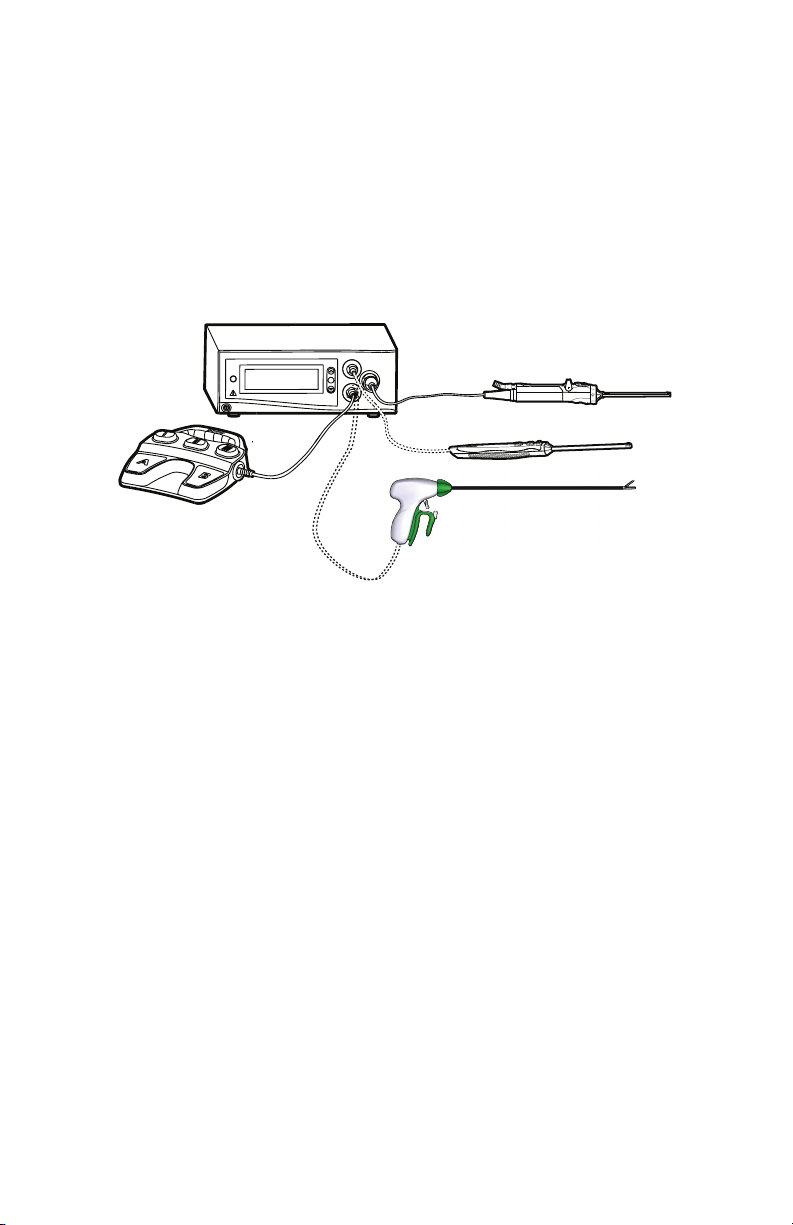
Illustrated below, the Crossre2 system consists of the following components:
1
2
DRAFT
3
5
4
1. Crossre2 Console (featured in this manual)
• Acts as a connection hub for the various components of the Crossre2
system
• Powers a motorized shaver handpiece for the mechanical cutting and
debridement of bone and soft tissue
• Generates bipolar radio frequency (RF) energy for vessel sealing and the
electrosurgical cutting and coagulation of tissue
• Provides a central user interface for operating the Crossre2 system
2. Disposable RF probe
Enables RF cutting and coagulation
3. Powered shaver handpiece (and disposable attachments)
Enables arthroscopic cutting and debridement
4. Crosseal Handpiece
Enables vessel sealing
5. Crossre Footswitch
Provides remote, foot control of the powered shaver handpiece and RF
probe
EN-7
Page 10

Package Contents
Carefully unpack the Crossre2 console and inspect each of the following
components. Report any damaged components to Stryker.
(1) Crossre2 console
(1) Hospital-grade power cord
(1) User guide
Available Accessories
The Crossre2 system is compatible with the following accessories:
System Accessories
0475-000-100 Crossre Footswitch
0277-200-100 iSWITCH Universal Wireless Footswitch Receiver
0277-200-101 iSWITCH Universal Wireless Footswitch Receiver (AUS)
0277-100-100 iSWITCH Universal Wireless Footswitch
6000-001-020 Stryker rewire cable
Arthroscopy Accessories
0279-xxx-xxx SERFAS Energy family of electrosurgical probes
0375-708-500 Formula 180 Handpiece
0375-704-500 Formula Handpiece (with buttons)
0375-701-500 Formula Handpiece (without buttons)
0275-601-500 Small-Joint Shaver Handpiece
DRAFT
Laparoscopy Accessories
0250-080-800 35 cm Crosseal Vessel Sealing Handpiece
0250-080-850 45 cm Crosseal Vessel Sealing Handpiece
EN-8
Page 11

The Crossre2 Console
The Crossre2 console is the connection hub for the components of the
Crossre2 system. It generates RF energy for ablation and vessel sealing,
powers motorized shavers, and provides user controls and system feedback.
Front Panel
The front console panel features ports for connecting handpieces, controls for
adjusting handpiece settings, and an LCD screen to provide system feedback.
1 2
3 4
DRAFT
5 6 7 8 9
1. Menu Selects menu items
2. Select Selects which device displays on
the LCD screen.
3. RF connector
(SERFAS Energy and
Crosseal Handpieces)
4. Handpiece connector Powered shaver handpiece
5. Power Powers the console on and o
Delivers RF energy for ablation or
vessel sealing handpieces
6. Error indicator Shines red to indicate errors
(error details appear in the LCD)
7. LCD screen Provides system feedback
8. Adjust Adjusts options for connected
devices
9. Footswitch connector Crossre Footswitch
EN-9
Page 12
Rear Panel
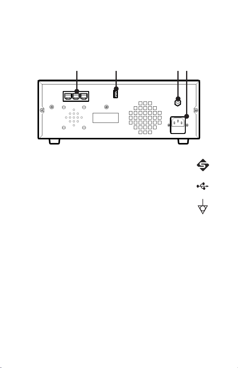
The rear panel provides ports for connecting the console to other Stryker
equipment.
1 2 3 4
DRAFT
1. Firewire Connectors Enables connection to other Stryker
Firewire devices, such as the iSWITCH
Universal Wireless Footswitch
2. USB Drive Enables software installation from
authorized service personnel
3. Equipotential
Ground Plug
—
4. AC Power Inlet —
EN-10
Page 13
The Crossre2 Interface
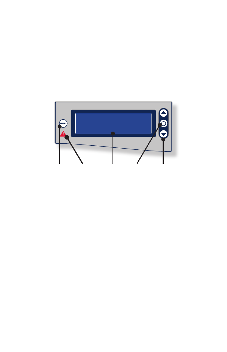
The Crossre2 interface displays system status, enables you to choose
between RF ablation, RF vessel sealing, and shaver modes, and enables you to
adjust power and speed settings.
Activating the actual handpieces is performed through controls on the
handpiece and on the Crossre Footswitch.
DRAFT
1 4 52 3
Control Description
1. Menu The Menu button opens a menu for selecting user and
system settings.
2. Error
indicator
3. LCD screen The LCD screen displays system status, error codes, mode
4. Select The Select button toggles between RF and Shaver
5. Adjust The Adjust buttons increase/decrease speed and power
The Error indicator shines red when a system error
occurs.
of operation, cutting speed, and power levels.
controls. The selected device can then be controlled
using the Crossre2 interface.
settings for the selected device.
EN-11
Page 14

Arthroscopy Mode
Indications for Arthroscopic Use
The Stryker Crossre 2 system is indicated for use in orthopedic and
arthroscopic procedures for the following joints: knee, shoulder, ankle, elbow,
wrist, and hip. The crossre system provides abrasion, resection, debridement
and removal of bone and soft tissue through its shaver blade; and the ablation
and coagulation of soft tissue, as well as hemostasis of blood vessels, through
its electrosurgical probe. Examples of uses of the prodict include resection
of torn knee cartilage, subcromial decompression, and resection of synovial
tissue in other joints.
Contraindications
The electrosurgical probe should not be used in procedures where a
nonconductive irrigant is used or with patients having cardiac pacemakers or
other electronic implants.
DRAFT
EN-12
Page 15

Setup and Device Connections
Stryker Endoscopy considers instructional training an integral part of the
Crossre2 system. Your Stryker Endoscopy sales representative will perform
at least one inservice at your convenience to help you set up your equipment
and instruct you and your sta on its operation and maintenance. Please
contact your local Stryker Endoscopy representative to schedule an in-service
after your equipment has arrived.
Warning Be sure that no liquid is present between connections
to the console and the handpiece. Connection of wet
accessories may lead to electric shock or electrical short.
To avoid the risk of electric shock, this equipment must only be connected
to a supply mains with protective earth.
Use only hospital-grade power cables. Using other cables may result in
increased RF emissions or decreased immunity from such emissions.
Only the handpieces and disposable attachments are suitable for use in the
patient environment. The console and footswitch are not sterile devices and
should not enter the sterile eld.
The Crossre2 System is compatible only with the Stryker handpieces and
footswitches listed in this manual. Do not connect any equipment not
specied in this manual, as unexpected results or serious injury will occur.
DRAFT
EN-13
Page 16
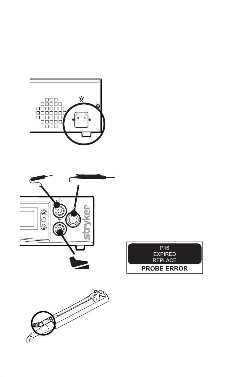
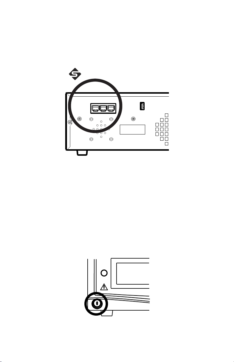
1. Place the console on a sturdy platform, such as a Stryker cart.
• Select a location according to the recommendations in the preceding
EMC tables.
• Leave four inches of space around all sides for convection cooling.
2. Connect the AC power.
DRAFT
3. Connect the handpieces and
footswitch. (Note: Vessel sealing
handpieces are not intended to
be connected during arthroscopic
procedures.)
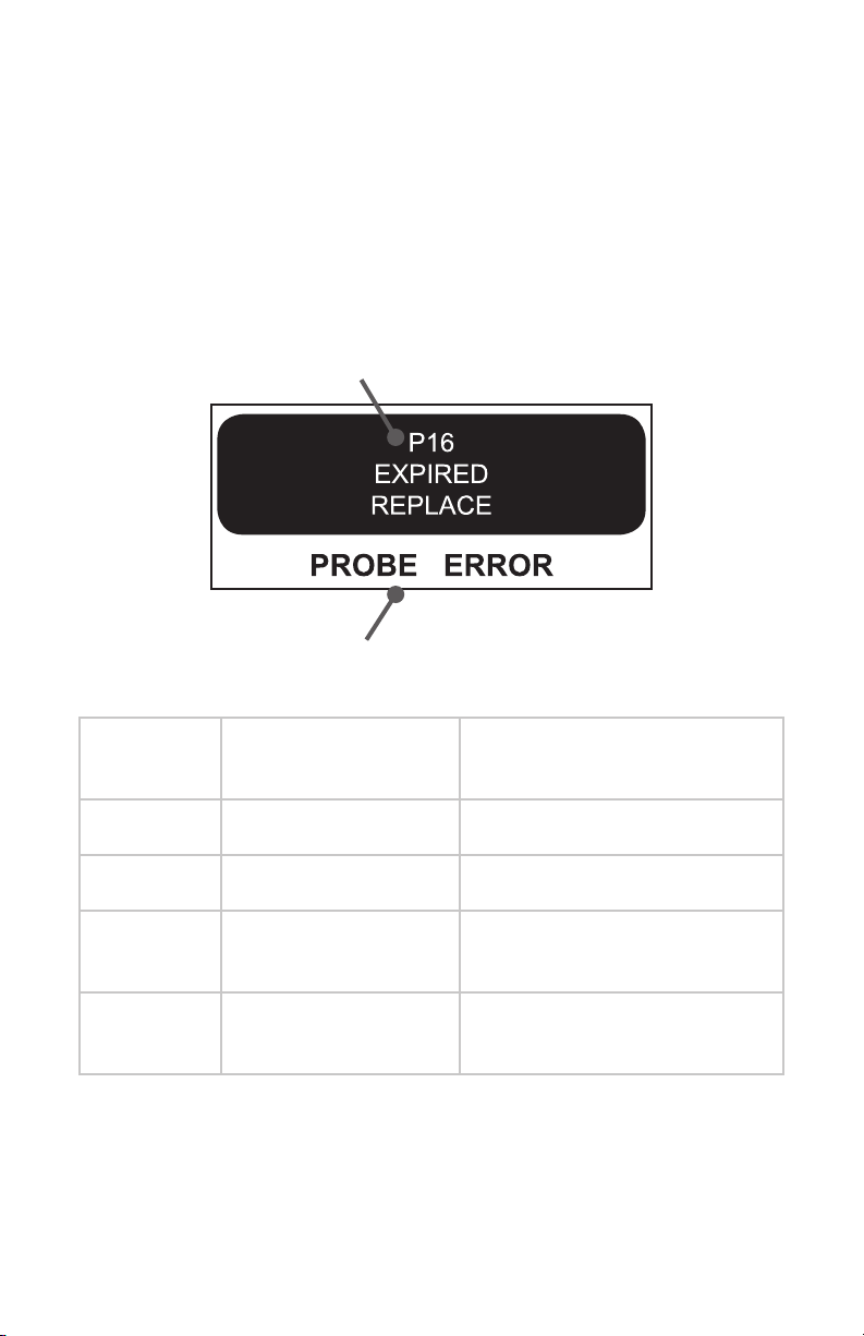
The console will display an error
message if expired or used
attachments are connected:
EN-14
4. Connect suction tubing (for all
suction-capable devices).
Page 17
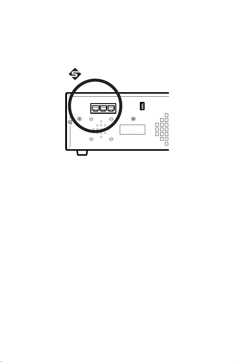
Using the iSWITCH Wireless Footswitch
The Crossre2 system can be used with the iSWITCH Wireless Footswitch
System.
DRAFT
1. Connect the Crossre2 console to the iSWITCH console using one of
the Firewire connection ports on each console.
2. Consult the iSWITCH Operating and Maintenance Manual (P/N1000400-700) for further operation instructions.
EN-15
Page 18
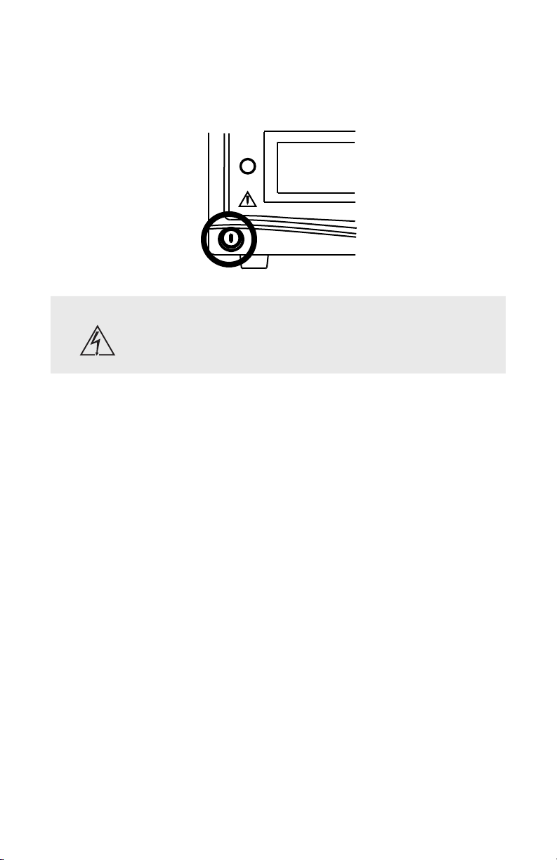
Powering the Console On and O
Press the power button to power the console on and o. The button will shine
green when the console is on.
DRAFT
Warning Should emergency shutdown become necessary, power
o the console as described above. As an added safety
measure, the console can be separated from the AC power
mains by detaching the AC power cord from either end.
EN-16
Page 19
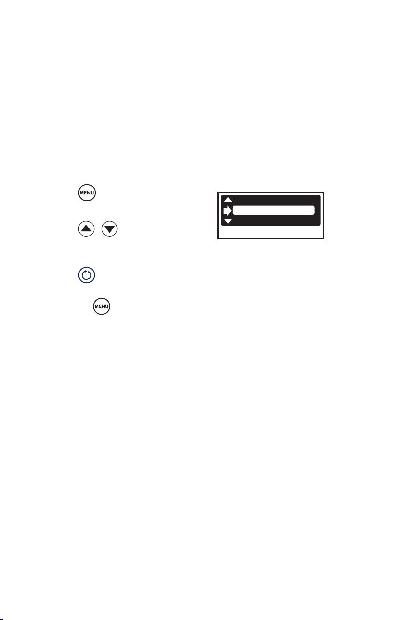
Adjusting User and System Settings
User Preference Settings
User preferences, such as power and cutting speeds and button assignments
for the handpiece and footswitch, can be adjusted through the Crossre2
interface.
Select from the default settings provided with the console, or contact your
Stryker representative to customize your own.
1. Press
2. Press
default setting.
3. Press to conrm
selection and exit.
Or, press
selection.
Note: User preference settings will not take eect unless a disposable
attachment is connected to the shaver.
.
DRAFT
to select a
to cancel
DEFAULT
SMITH KNEE
SMITH SHLDR
EN-17
Page 20
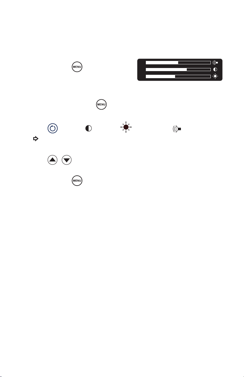
System Settings
System settings, such as screen brightness, contrast, and system sound can be
adjusted through the Crossre2 interface.
1. Press and hold .
(Note: If an RF probe is connected to
the console, the COAG adjustment
screen will appear. Press
access the system settings screen.)
2. Press to choose (contrast),
3. Press
4. Press and hold to exit.
(Note: A short press will display the current version of the console
software.)
DRAFT
will indicate your selection.)
to adjust.
again to
(brightness), or (sound). (The
EN-18
Page 21
Arthroscopic Shaver Controls
Warning The Crossre2 system is intended for use only by licensed
medical professionals, properly trained in the use of
electrosurgical equipment and techniques. The Crossre2
system generates potentially hazardous levels of energy
that can result in injury or even death if improperly used.
Before using the Crossre2 system in an actual procedure, verify that each
component is installed and functioning properly. Improper connection may
cause arcing or malfunction of the handpiece or console, which can result in
injury, unintended surgical eect, or product damage.
During use, operators should wear standard surgical gloves to help reduce
the risk of electric shock.
Warning During use, the RF, Crosseal, and shaver handpieces
Shaver handpieces are provided nonsterile and must be cleaned and
sterilized prior to each use, according to the reprocessing instructions
provided in the handpiece manual.
DRAFT
generate electronic noise that may interfere with EKG
readings. Before responding to any erratic EKG readings,
rst power down the system to ensure the readings are not
the result of system noise.
EN-19
Page 22
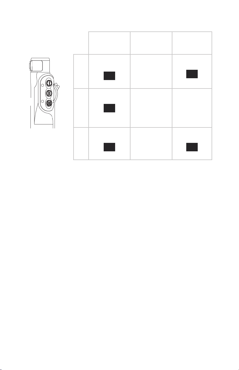
Default Handpiece Controls
Default 1 Default 2 /
1. Oscillate
(one touch)
1
TOUCH
None
Activate /
Deactivate
Default 3
Oscillate
(one touch)
1
TOUCH
1
2. Forward
2
3
(one touch)
1
TOUCH
Select Mode:
Oscillate or
Forward /
Reverse
Jog
DRAFT
3. Reverse
(one touch)
1
TOUCH
Note: Default settings can be selected in the User Preference Settings screen
on the console. Settings will not take eect until a disposable attachment is
connected to the shaver handpiece.
Forward/
Reverse
Forward
(one touch)
1
TOUCH
EN-20
Page 23
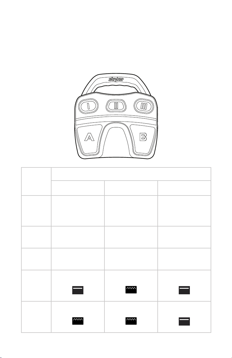
Default Footswitch Controls
The RF and shaver handpieces can also be controlled by the Crossre
Footswitch. The default footswitch controls for the shaver handpiece are
shown below. To customize button assignments, contact your Stryker
representative.
DRAFT
Button Function
Default 1 Default 2 / None Default 3
I Jog Select Mode:
Oscillate or
Forward/Reverse
II Select Handpiece:
RF or Shaver
III Select Direction:
Forward or Reverse
A Oscillate
(xed)
FIXED
B Forward/Reverse
(variable)
VAR
Select Handpiece:
RF or Shaver
Select Speed:
High or Low
Oscillate/Reverse
(variable)
VAR
Oscillate/Forward
(variable)
VAR
Select Mode:
Oscillate or
Forward/Reverse
Select Handpiece:
RF or Shaver
Select Speed:
High or Low
Oscillate/Reverse
(xed)
FIXED
Oscillate/Forward
(xed)
FIXED
EN-21
Page 24

Note: When using small-joint handpieces, only Default 2 settings are
available. No other defaults or user preferences can be applied.
Adjusting Cutting Speed
Use the
speed setting for the active handpiece.
Note: In shaver mode, the console uses radio frequency identication (rfid) to
automatically detect which type of disposable attachment is connected to the
handpiece. Upon recognition, the console adjusts to an optimal preset cutting
speed, direction, and power.
Note: Forward and reverse settings are adjusted independent of each other.
Adjusting settings in one mode will not aect the other.
buttons on the console to manually adjust the power or
DRAFT
EN-22
Page 25
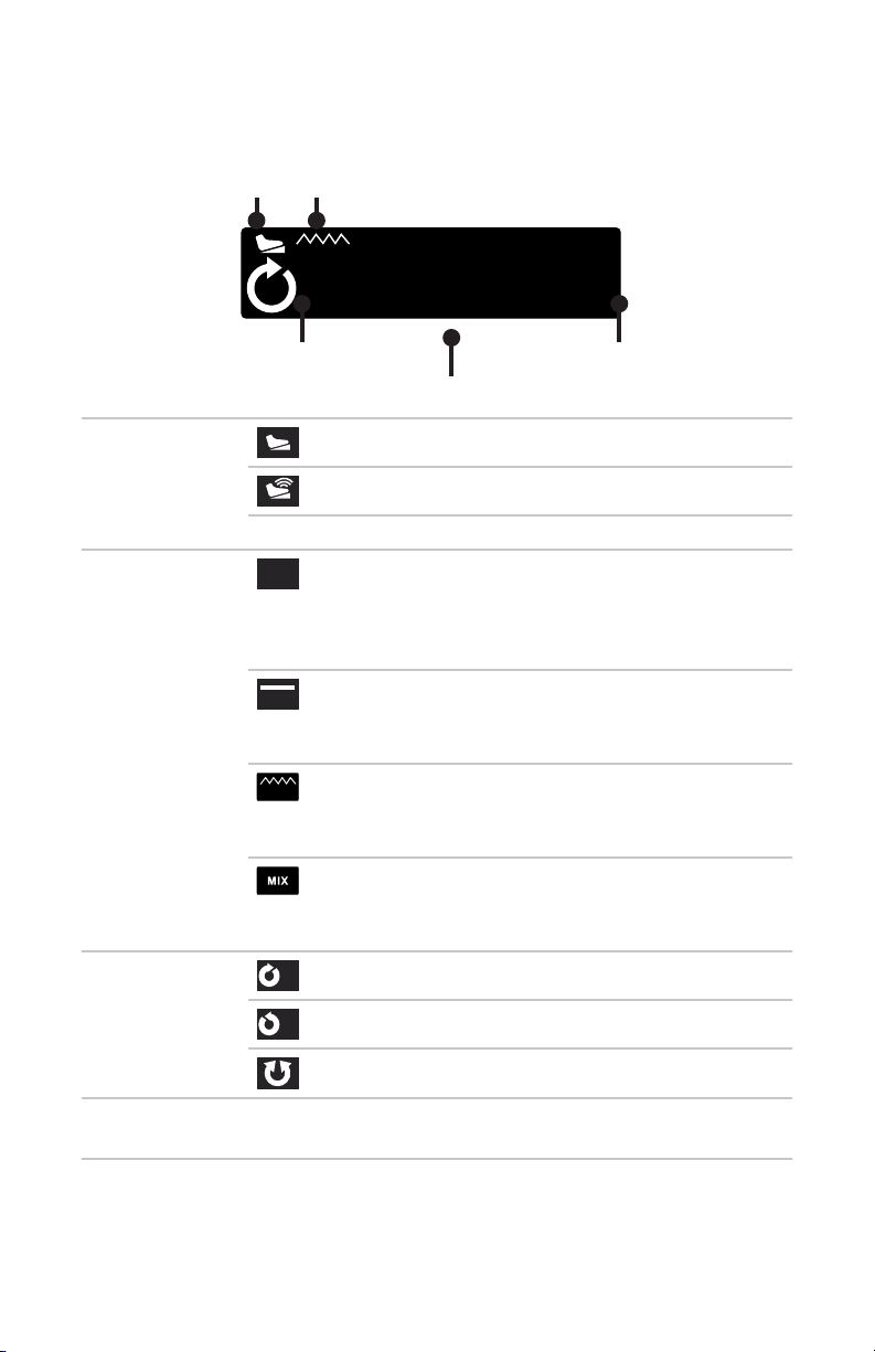
Reading the LCD
In shaver mode, the LCD will show:
1 2
VAR
1. Footswitch
status
2. Footswitch
response
3. Direction
DRAFT
F
9000
MC DISP NAME
3 5
4
Crossre Footswitch connected
iSWITCH footswitch connected
not connected
1
one touch
TOUCH
(pressing the foot pedal once will activate the
shaver to a default speed; pressing again will stop
it)
xed
FIXED
(pressing the foot pedal at any pressure will result
in a constant speed)
variable
VAR
(shaver speed will vary, depending on the pressure
applied to the foot pedal)
mix
(oscillate speed is xed; forward/reverse speed is
variable)
forward
F
reverse
R
oscillate
4. Cutter
name
5. Speed (#) rotations per minute
(name)
EN-23
Page 26

System Feedback
Event Audible Feedback Visible Feedback
(via LCD)
Reverse activated ve high beeps
Forward activated/
resumed
Adjustments made to
speed settings
low beep
one beep for each unit
of change
DRAFT
R
F
Speed indicator
number increases or
decreases
EN-24
Page 27
RF Ablation Controls
Warning During use, the RF, Crosseal, and shaver handpieces
generate electronic noise that may interfere with EKG
readings. Before responding to any erratic EKG readings,
rst power down the system to ensure the readings are not
the result of system noise.
RF and Crosseal handpieces are intended for single use only and should not
be reprocessed or reused.
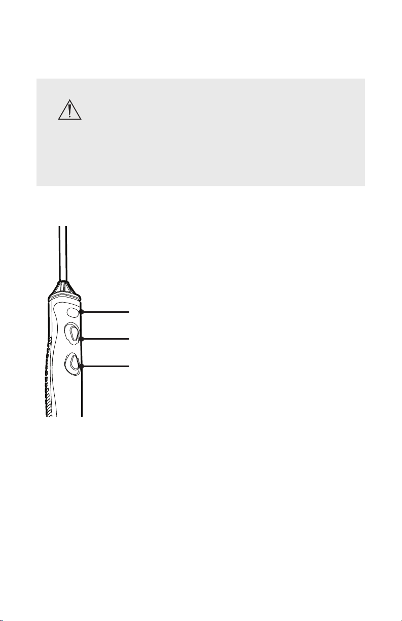
Default handpiece controls
DRAFT
1. Adjust CUT power level (single press)
1
Activate/deactivate Force Modulation
2
2. Activate CUT
3
3. Activate COAG
or
(press and hold for three seconds)
EN-25
Page 28
Default footswitch controls
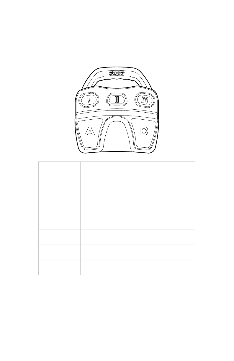
The RF and shaver handpieces can also be controlled by the Crossre
Footswitch. The default footswitch controls for the RF probe are shown below.
To customize button assignments, contact your Stryker representative.
DRAFT
Button Function
(controls are the same for defaults
1, 2, and 3)
EN-26
I Decrease Cut Level
II Select Handpiece:
RF or Shaver
III Increase Cut Level
A Cut
B Coag
Page 29
Adjusting CUT power
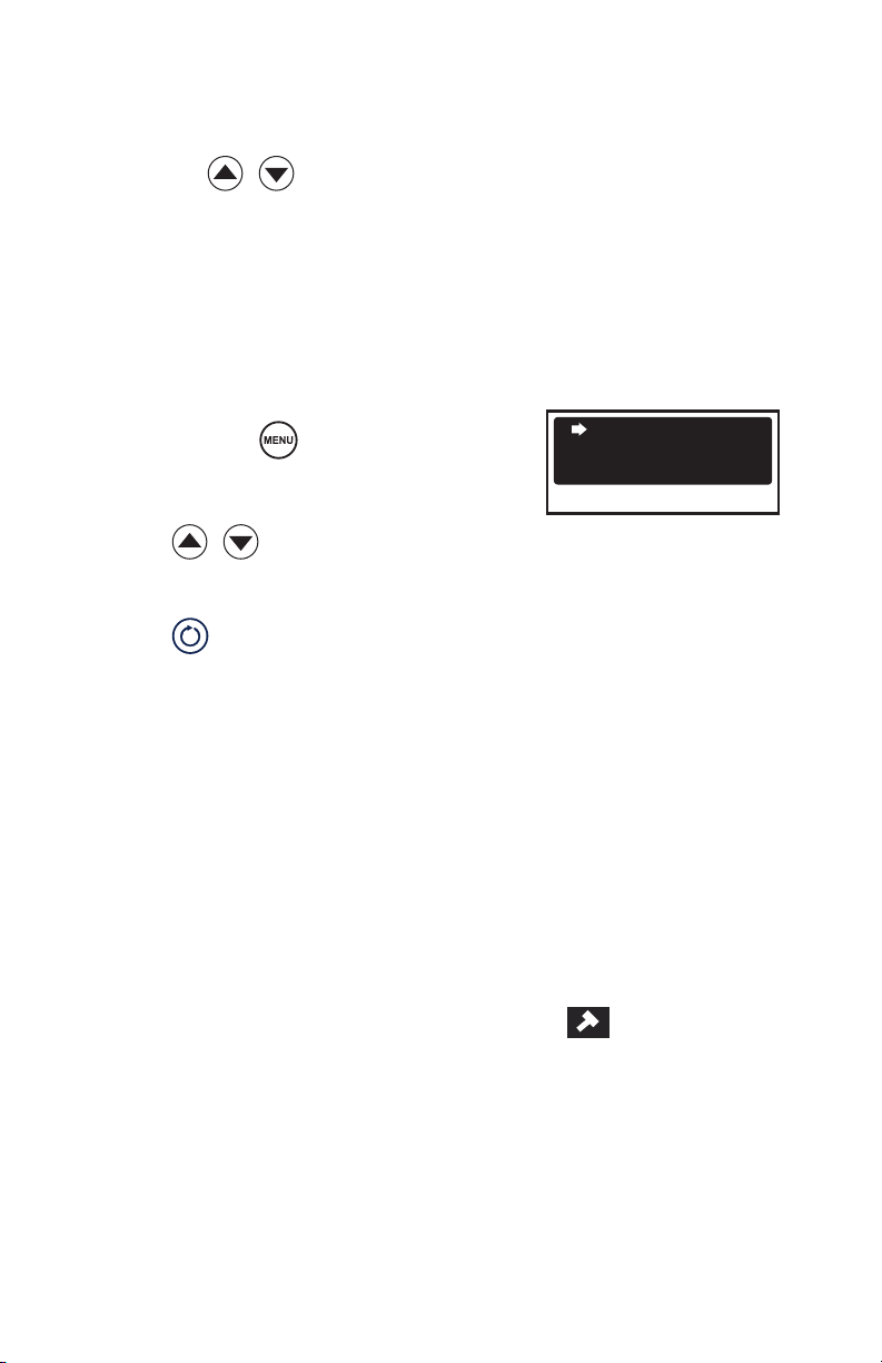
To adjust CUT power:
• Press the
• Press the gray button on the handpiece (increase)
• Press the I (decrease) and III (increase) buttons on the footswitch
buttons on the console
Adjusting COAG power
To adjust COAG power:
1. Press and hold . The COAG POWER
LEVEL screen will appear.
2. Press
3. Press to confirm selection and exit.
Note: COAG power can only be adjusted when an RF probe is connected to
the console.
DRAFT
to adjust.
COAG1
COAG2
COAG3
COAG POWER LEVEL
Selecting Force Modulation
The Crossre2 Console features an additional RF mode known as Force
Modulation. Force Modulation is an alternative ablation mode that duty
cycles RF output at a low frequency to achieve a lower average power output
than in normal CUT mode.
Currently, Force Modulation is an option only with the following SERFAS
Energy probes: 90-S, 90-S Max, and Super 90-S.
• To activate Force Modulation, hold down the grey power button on the
SERFAS probe for three seconds. A hammer icon
LCD screen of the console, indicating Force Modulation activated.
• To deactivate Force Modulation, hold down the grey power button on the
SERFAS probe for three seconds. The hammer icon will disappear from the
LCD screen.
will appear on the
EN-27
Page 30
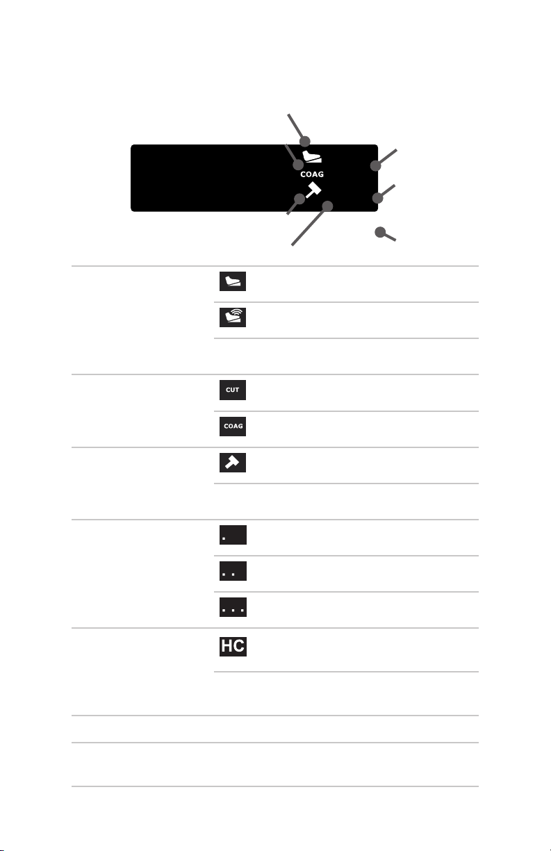
Reading the LCD
In RF ablation mode, the LCD will show:
1
1. Footswitch status
2. Mode
3. Force modulation
4. COAG power
DRAFT
2
11
HC
. . .
SERFAS
3
4
Crossre Footswitch connected
iSwitch footswitch connected
not connected
cut mode activated
coagulation mode activated
force modulation activated
force modulation not activated
low
5
6
7
medium
high
5. Hand controls
6. CUT power (#) power setting
7. Disposable RF
probe name
EN-28
(name)
hand control is enabled
hand control is disabled
Page 31
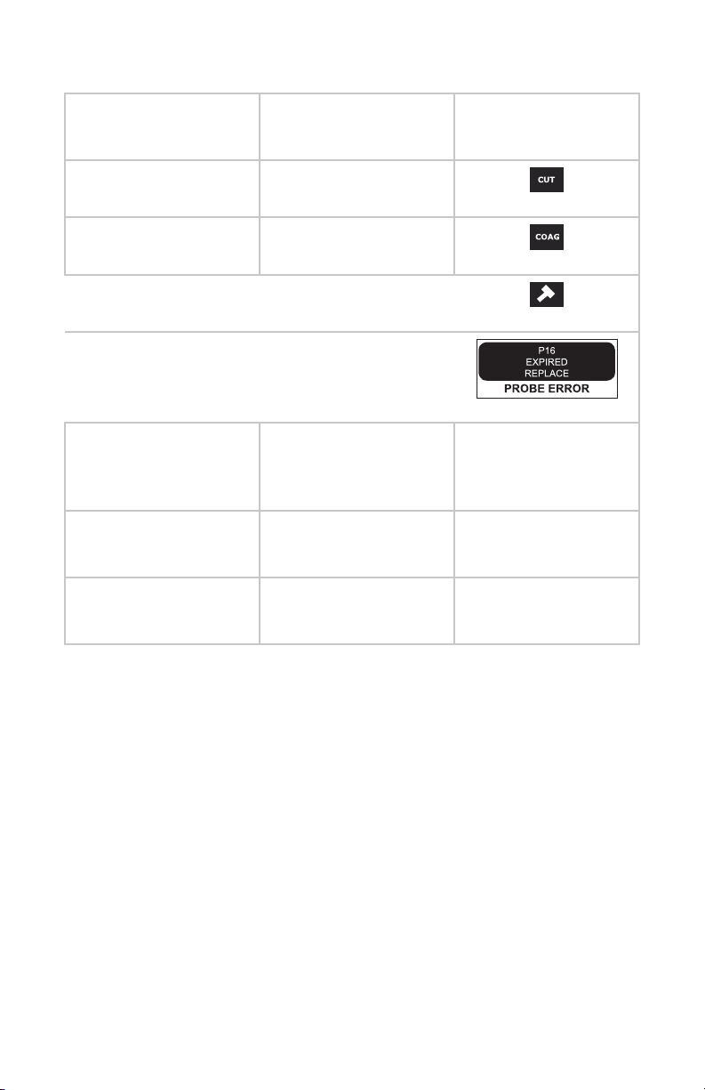
System Feedback
Event Audible Feedback Visible Feedback
CUT activated high, steady tone
COAG activated low, steady tone
(via LCD)
Force modulation
on / o
System error Ten short beeps
Single beep
DRAFT
Adjustments made to
power settings
Change footswitch to
control RF mode
Change footswitch to
control Shaver mode
one beep for each unit
of change
“SERFAS” “SERFAS” appears
“Shaver” disposable name
CUT power indicator
number increases or
decreases
appears
EN-29
Page 32

Dual Controls
In arthroscopic procedures, RF probes and arthroscopic shaver handpieces
can be simultaneously connected to the Crossre 2 system, enabling users to
toggle quickly between RF ablation and arthroscopic functions.
Selecting between RF Ablation Mode and Arthroscopic
Shaver Mode for Footswitch Control
Selecting a mode will enable the selected handpiece to be controlled by the
footswitch. To select the appropriate mode, do one of the following:
• Press on the Crossre2 interface. The interface will toggle between
modes. The device controlled by the footswitch will appear on the right
side of the LCD and will be identied by the
• Press the toggle button (II) on the footswitch.
Note: Either handpiece can be activated at any time by pressing the button on
the handpiece.
Activating a handpiece
To activate a handpiece in dual mode, do one of the following:
• Press any button on the desired handpiece.
• Press the footswitch pedal for the active handpiece. (The active is
identied by handpiece appears on the right side of the LCD.)
DRAFT
icon.
EN-30
Page 33
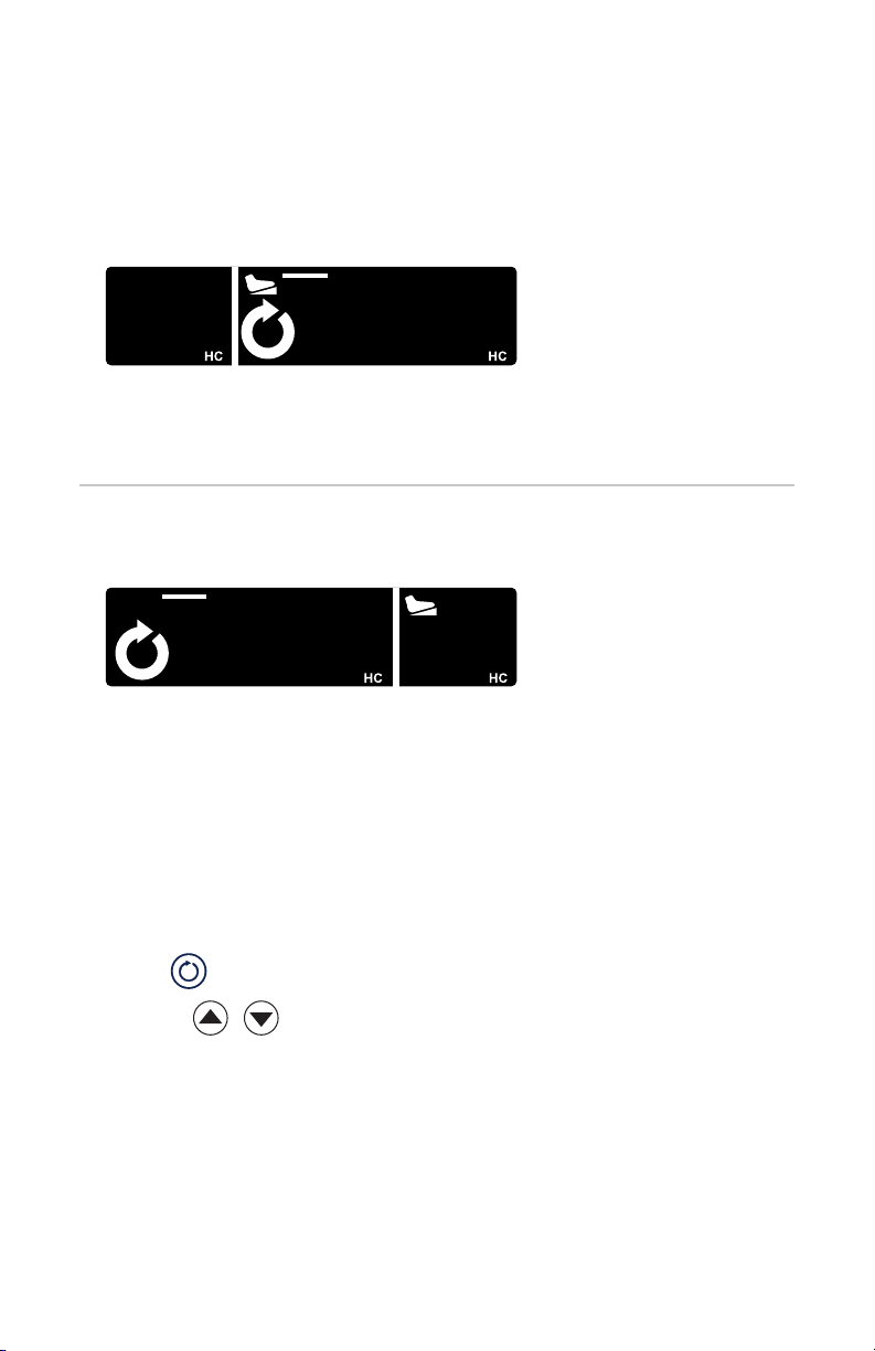
Reading the LCD
In dual mode, the LCD will show the status of both devices. Whichever device
is controlled by the footswitch will appear on the right side of the LCD.
FIXED
11
SERFAS MC DISP NAME
9000
F
Dual mode, shaver
handpiece controlled by
footswitch.
DRAFT
FIXED
9000
F
Adjusting handpiece settings with the console
In dual mode, settings can be adjusted for whichever handpiece appears on
the right side of the LCD.
11
SERFASMC DISP NAME
Dual mode, RF probe
controlled by footswitch.
1. Press to move the desired handpiece to the right side of the LCD.
2. Use the
speed setting for the selected handpiece.
buttons on the console to manually adjust the power or
EN-31
Page 34

Laparoscopy Mode
Indications for Laparoscopic and
General Surgery Use
The Stryker Crossre 2 system is indicated for use in laparoscopic general and
gynecological surgical procedures (including urologic, thoracic, plastic and
reconstructive, bowel resections, hysterectomies, cholecystectomies, gall
bladder procedures, Nissen fundoplication, adhesiolysis, oophorectomies,
etc.), or any procedure where vessel ligation (cutting and sealing), tissue
grasping and dissection is performed. The devices can be used on vessels
up to and including 7 mm and bundles as large as will t in the jaws of the
instruments.
Contraindications
• The system should not be used with atherosclerotic vessels (calcied
vessels) as vessels will not seal.
• Crosseal should not be used in procedures where a nonconductive
irrigant is used or with patients having cardiac pacemakers or other
electronic implants.
• The Crosseal system should not be used for tubal ligation.
DRAFT
EN-32
Page 35

Setup and Device Connections
Stryker Endoscopy considers instructional training an integral part of the
Crossre2 system. Your Stryker Endoscopy sales representative will perform
at least one inservice at your convenience to help you set up your equipment
and instruct you and your sta on its operation and maintenance. Please
contact your local Stryker Endoscopy representative to schedule an in-service
after your equipment has arrived.
Warning Be sure that no liquid is present between connections
to the console and the handpiece. Connection of wet
accessories may lead to electric shock or electrical short.
To avoid the risk of electric shock, this equipment must only be connected
to a supply mains with protective earth.
Use only hospital-grade power cables. Using other cables may result in
increased RF emissions or decreased immunity from such emissions.
Only the handpieces and disposable attachments are suitable for use in the
patient environment. The console and footswitch are not sterile devices and
should not enter the sterile eld.
The Crossre2 System is compatible only with the Stryker handpieces and
footswitches listed in this manual. Do not connect any equipment not
specied in this manual, as unexpected results or serious injury will occur.
DRAFT
EN-33
Page 36
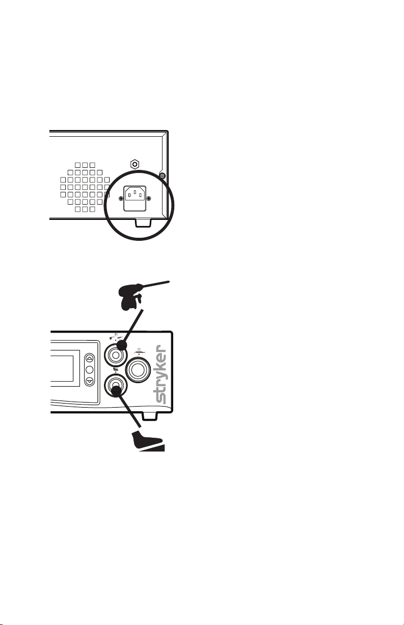
1. Place the console on a sturdy platform, such as a Stryker cart.
• Select a location according to the recommendations in the preceding
EMC tables.
• Leave four inches of space around all sides for convection cooling.
2. Connect the AC power.
DRAFT
3. Connect the handpiece and
footswitch. (Note: Arthroscopic
handpieces are not intended to
be connected during laparoscopic
procedures.)
EN-34
Page 37
Using the iSWITCH Wireless Footswitch
The Crossre2 system can be used with the iSWITCH Wireless Footswitch
System.
DRAFT
1. Connect the Crossre2 console to the iSWITCH console using one of
the Firewire connection ports on each console.
2. Consult the iSWITCH Operating and Maintenance Manual (P/N1000400-700) for further operation instructions.
Powering the Console On and O
Press the power button to power the console on and o. The button will shine
green when the console is on.
EN-35
Page 38
Warning Should emergency shutdown become necessary, power
o the console as described above. As an added safety
measure, the console can be separated from the AC power
mains by detaching the AC power cord from either end.
Adjusting User and System Settings
User Preference Settings
User preferences, such as button assignments for the handpiece and
footswitch, can be adjusted through the Crossre2 interface.
Select from the default settings provided with the console, or contact your
Stryker representative to customize your own.
DRAFT
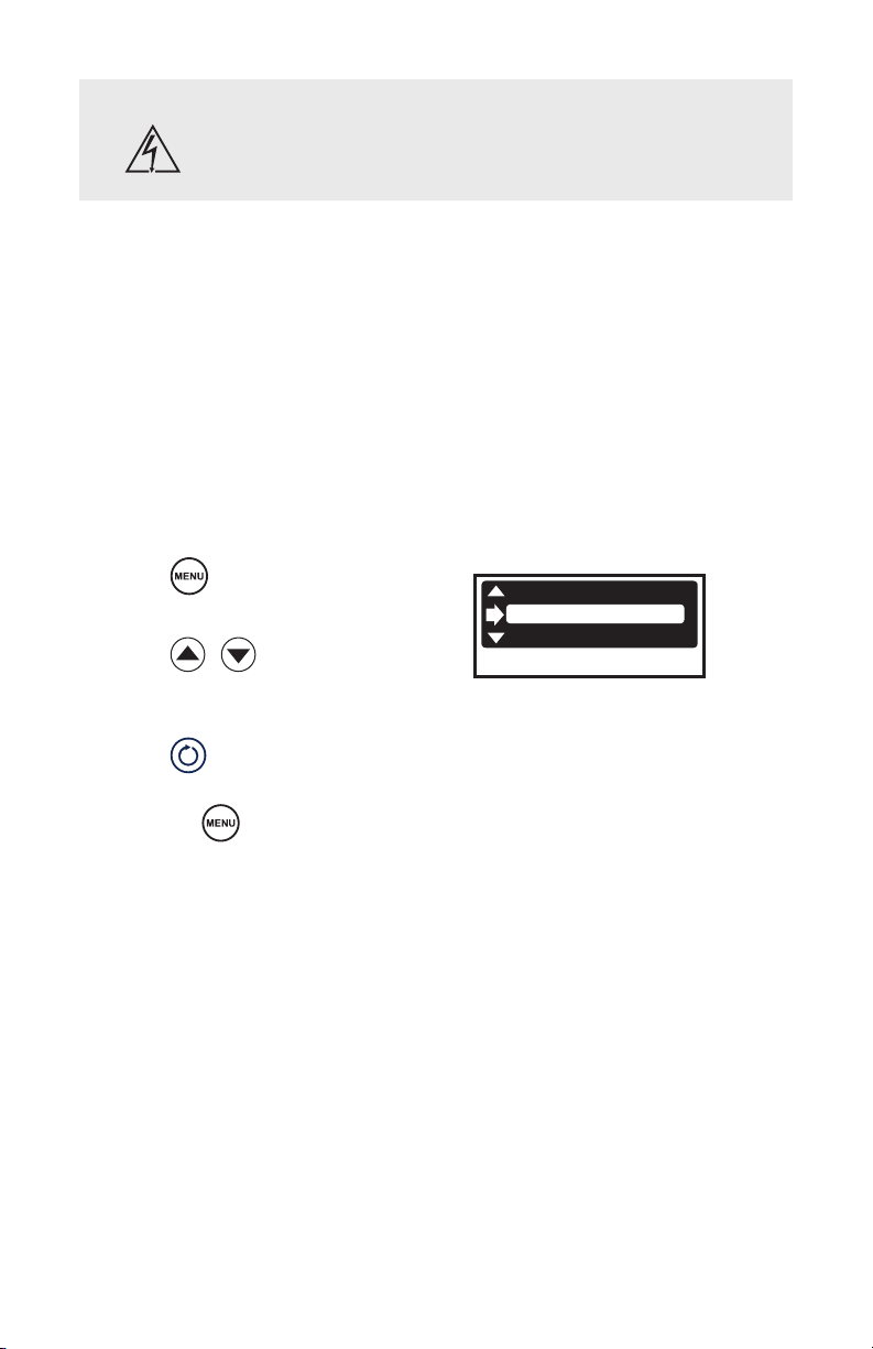
1. Press
2. Press
default setting.
3. Press to conrm
selection and exit.
Or, press
selection.
.
to select a
to cancel
DEFAULT
SMITH KNEE
SMITH SHLDR
EN-36
Page 39
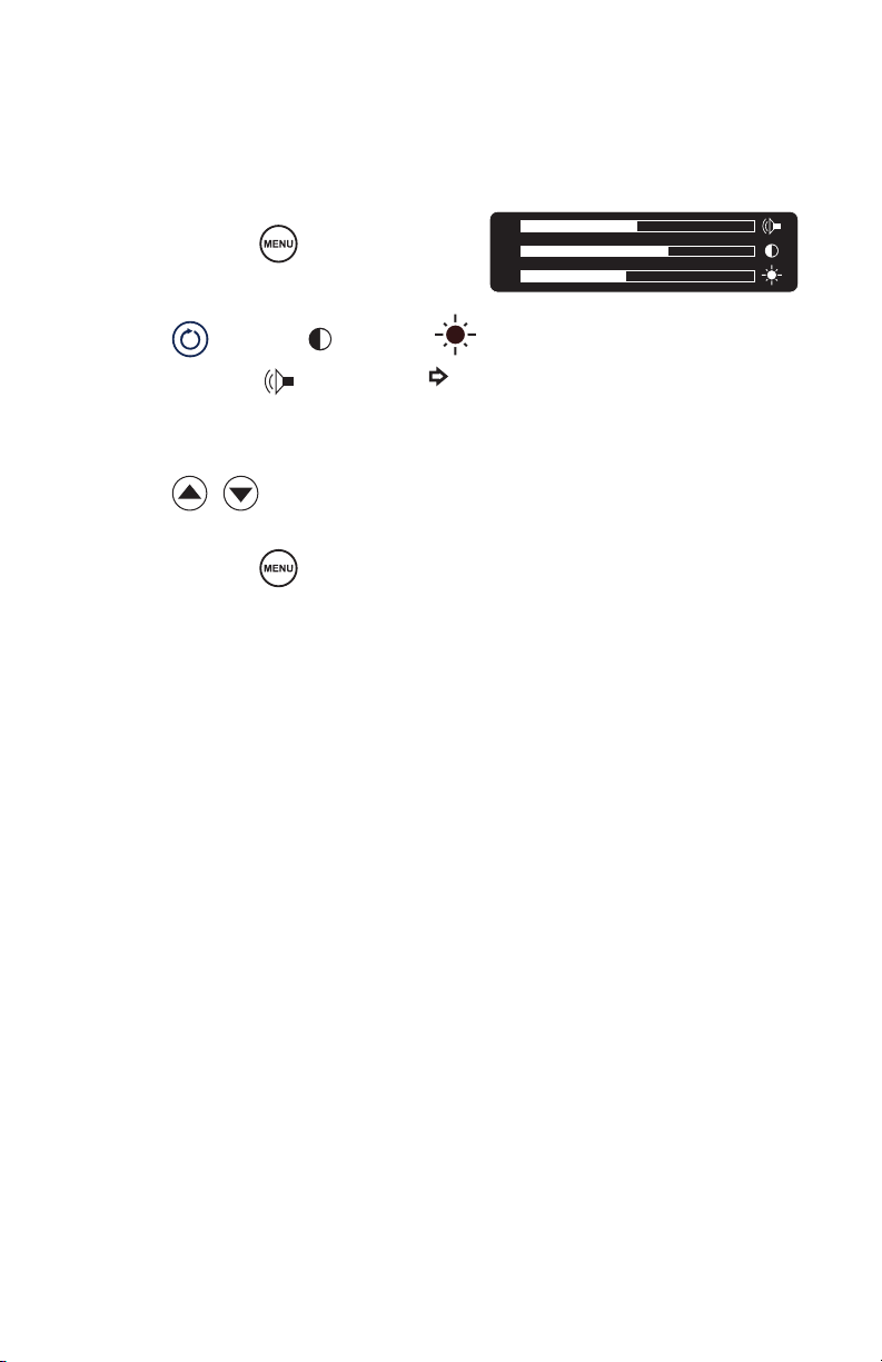
System Settings
System settings, such as screen brightness, contrast, and system sound can be
adjusted through the Crossre2 interface.
1. Press and hold .
2. Press to choose (contrast),
(brightness), or (sound). (The will
indicate your selection.)
DRAFT
3. Press
4. Press and hold to exit.
(Note: A short press will display
the current version of the console
software.)
to adjust.
EN-37
Page 40
Vessel Sealing Controls
Warning The Crossre2 system is intended for use only by licensed
medical professionals, properly trained in the use of
electrosurgical equipment and techniques. The Crossre2
system generates potentially hazardous levels of energy
that can result in injury or even death if improperly used.
Before using the Crossre2 system in an actual procedure, verify that each
component is installed and functioning properly. Improper connection may
cause arcing or malfunction of the handpiece or console, which can result in
injury, unintended surgical eect, or product damage.
During use, operators should wear standard surgical gloves to help reduce
the risk of electric shock.
Warning During use, the RF, Crosseal, and shaver handpieces
DRAFT
generate electronic noise that may interfere with EKG
readings. Before responding to any erratic EKG readings,
rst power down the system to ensure the readings are not
the result of system noise.
EN-38
RF and Crosseal handpieces are intended for single use only
and should not be reprocessed or reused.
Page 41
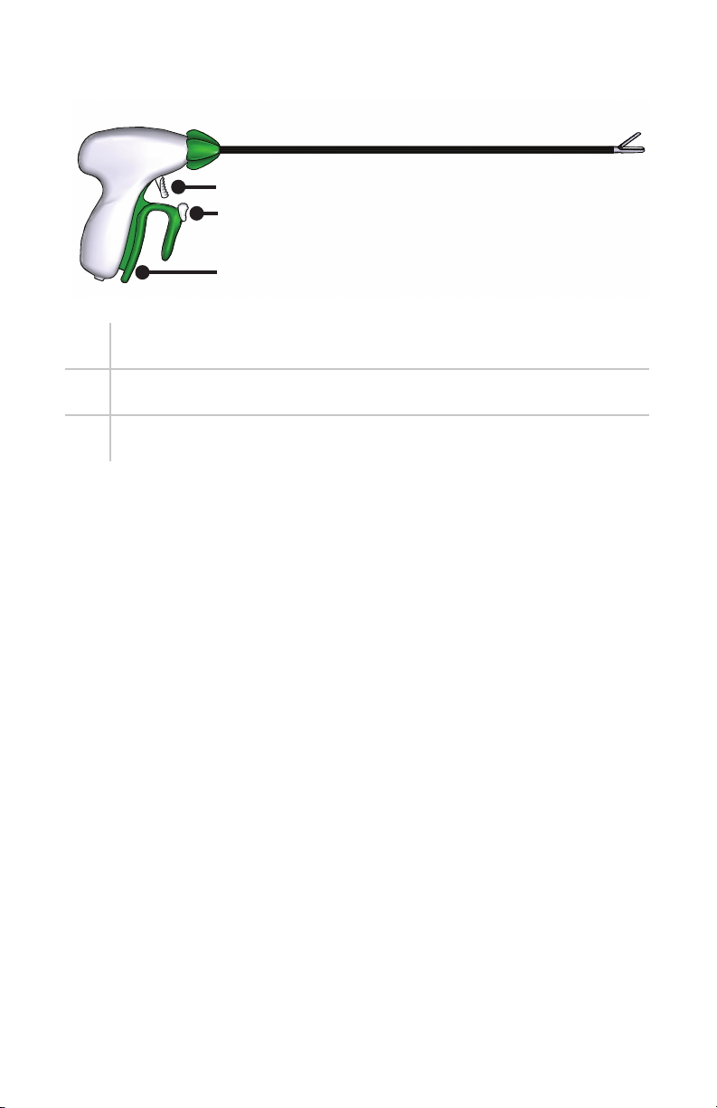
Default Handpiece Controls
3
2
1
1. grasp
2. seal
3. cut (mechanically)
Note: For complete instructions on how to use the Crosseal handpiece,
consult the Crosseal Handpiece User Guide (P17278).
DRAFT
EN-39
Page 42
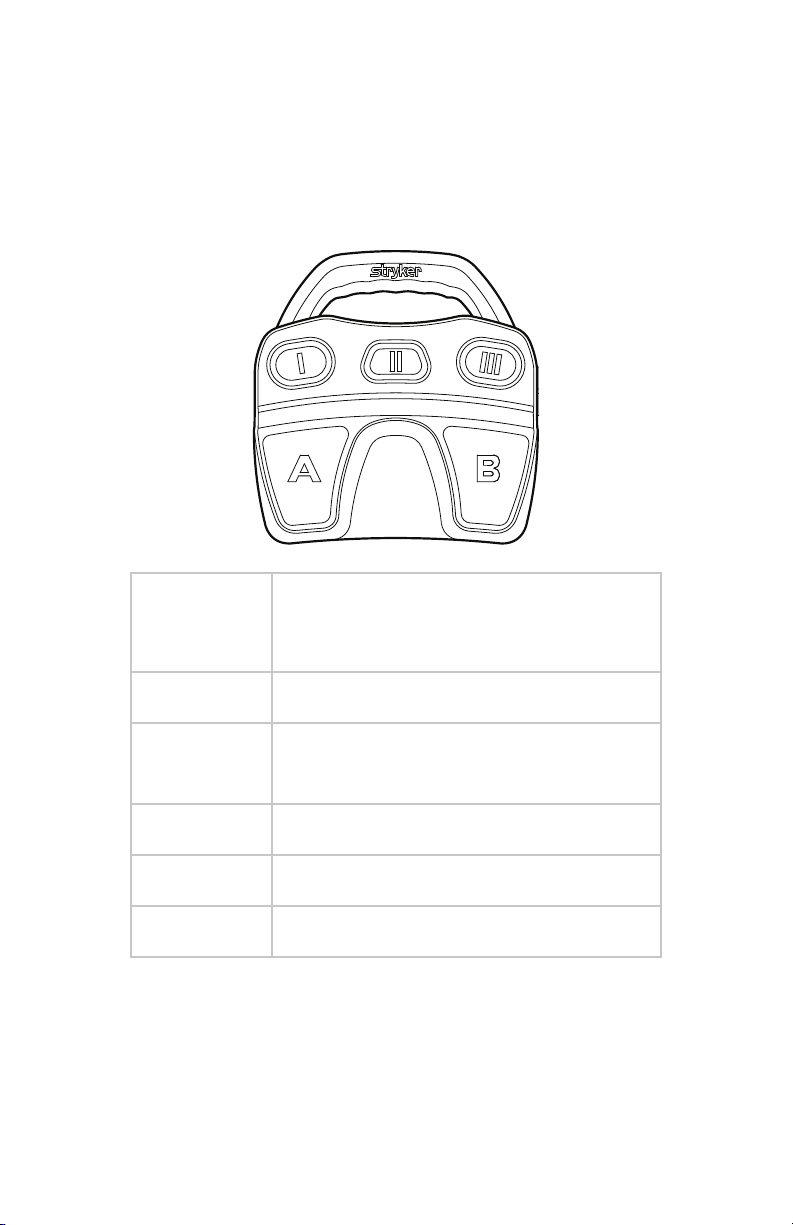
Default footswitch controls
The RF and shaver handpieces can also be controlled by the Crossre
Footswitch. The default footswitch controls for the vessel sealing handpiece
are shown below. To customize button assignments, contact your Stryker
representative.
DRAFT
Button Function
(controls are the same for defaults 1, 2, and
3)
EN-40
I Decrease Seal Level
II Select Handpiece:
RF, Crosseal, or Shaver
III Increase Seal Level
A Activate/Seal
B Activate/Seal
Page 43
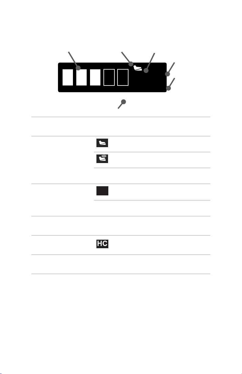
Reading the LCD
In vessel sealing mode, the LCD will show:
1
1. Progress
2. Footswitch status
3. Sealing status
4. Seal power
DRAFT
indicator
2 3
4
SEAL
3
HC
VESSEL SEALER
6
indicates progress of vessel sealing
Crossre Footswitch connected
iSwitch footswitch connected
not connected
SEAL
vessel sealing in progress
vessel sealing not in progress
(#) power setting
5
5. Hand controls hand control is connected and its
buttons are active
6. Handpiece
indicator
vessel sealing handpiece is connected
EN-41
Page 44
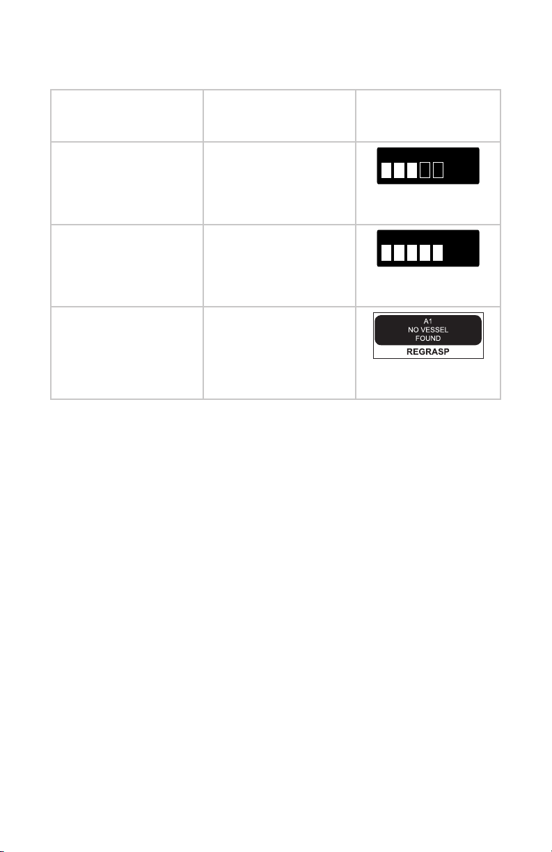
System Feedback
Event Audible Feedback Visible Feedback
(via LCD)
Sealing activated /
in progress
Sealing complete two high beeps
steady tone
DRAFT
Sealing error alternating high/low
tones
SEAL
progress bar
SEAL
progress bar
vessel-sealing error
EN-42
Page 45
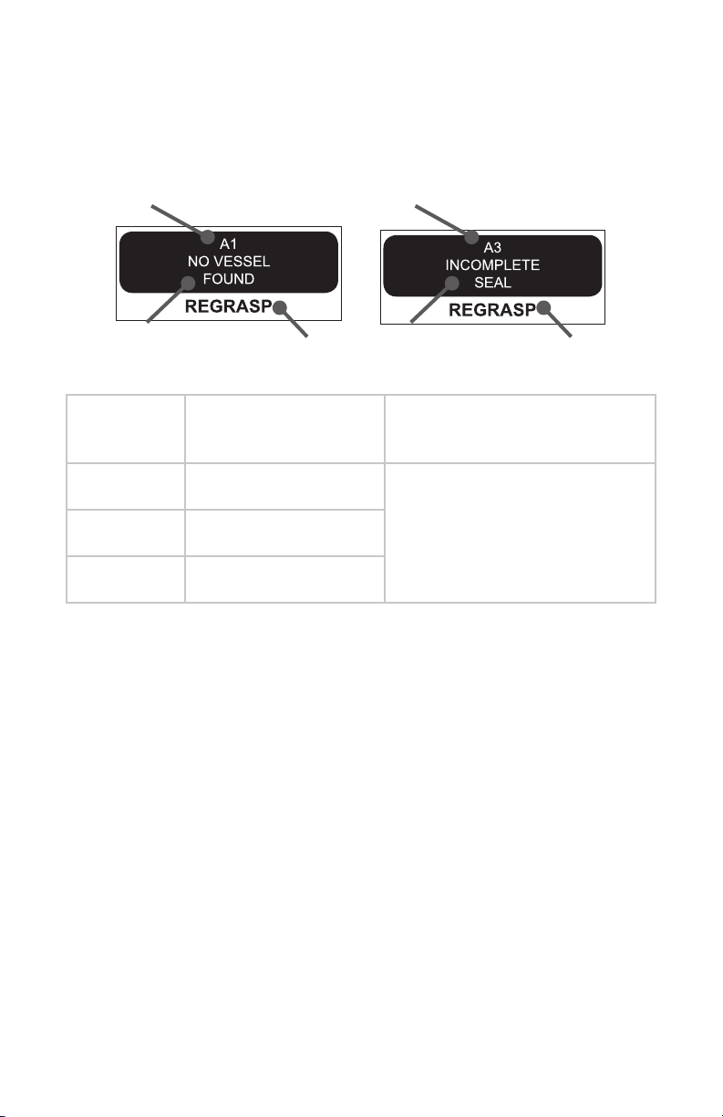
Vessel-Sealing Errors
During vessel sealing, the Crossre 2 system will indicate sealing progress.
Should a seal be unsuccessful, the LCD will display an appropriate error
message:
1
2 3
DRAFT
1.
Error Code
A1 No Vessel Found
A3 Incomplete Seal
Description
2.
1
2 3
Solution
Regrasp tissue and retry sealA2 Incomplete Seal
EN-43
Page 46

Troubleshooting
Problem Possible Solution
Console A hardware fault is
detected
• Turn the power o and on again.
• If the problem persists, contact a
Stryker representative or return
the console for repair.
The AC voltage is
incorrect
DRAFT
A software fault is
detected
The system does
not power on
The electrical
interference is
sporadic
The generator
temperature is too
high
A power-on self
test error has
occurred
• Turn the power off and on again.
• If the problem persists, contact a
Stryker representative or return
the console for repair.
• Turn the power off and on again.
• If the problem persists, contact a
Stryker representative or return
the console for repair.
• Check the power cord to ensure it
is properly connected.
• Check to ensure the cord is
connected to a grounded outlet.
• Power down all electrical
equipment not in use.
• Increase distance of other
electrical equipment.
• Connect the unit and other
equipment into dierent outlets.
• Ensure that there is proper airow
around the unit.
• Turn the power o and on again.
• If the problem persists, contact a
Stryker representative or return
the console for repair.
EN-44
Page 47

Handpiece
The temperature
is higher than
normal
• Allow the unit to cool before
restarting.
Disposable
Attachments
The unit has
reached its
recommended
service interval
RF probe is not
ready
RF probe is
expired
DRAFT
RF probe
identication is
invalid
RF probe
communication
error
Exceeded time
usage
RF power is too
high
RF voltage is too
high
• Contact your Stryker
representative.
• Check the connection to the
console.
• Replace probe.
• Replace probe.
• Check the connection to the
console.
• If necessary, replace probe.
• Replace probe
• Check the probe for damage.
• If necessary, replace probe.
• Check the probe for damage.
• If necessary, replace probe.
RF current is too
high
RF delivery
has exceeded
continuous limit
Low impedance
detected
Footswitch A wireless
footswitch is not
detected
The footswitch
icon does not
appear
• Check the probe for damage.
• If necessary, replace probe.
• Clear error and continue
• Check the probe for damage.
• If necessary, replace probe.
• Disconnect the wired footswitch.
• Ensure the unit is connected.
• Ensure that there is no damage to
the cable or connector.
EN-45
Page 48
Note: If a disturbance occurs on the video monitor, the user should ensure
that the probe cable is not near any other instrument cables.
Error Codes
When the Crossre 2 system encounters an error, it will display an error
code on the LCD. Error codes are grouped into general categories that share
common solutions:
1
DRAFT
2
1.
Error Code
A## Activation Errors Reactivate
E## System-level Errors Reboot system
P## Probe Errors Follow instructions on LCD, or
W## Warning Errors No action required;
EN-46
2.
Category
Solution
replace disposable attachment
informational only
Page 49

Cleaning and Maintenance
Cleaning
Console
Should the console need cleaning, wipe it down with a sterile cloth and mild
cleaning solution. If needed, wipe the console with a disinfectant.
Warning To avoid electric shock and potentially fatal injury,
unplug the Crossre2 console from the electrical outlet
before cleaning.
DRAFT
Do not sterilize the console or immerse it in any liquid.
Doing so will damage the unit.
Do not clean the console with alcohol, solvents, or
cleaning solutions that contain ammonia. Doing so will
damage the unit.
Footswitch
Consult the footswitch user guide for cleaning and reprocessing instructions.
RF Handpiece
RF handpieces are intended for single use only and should not be cleaned,
sterilized, or reused.
Shaver Handpiece
Consult the appropriate user guide for cleaning and reprocessing instructions.
Disposable attachments are intended for single use only and should not be
cleaned, sterilized, or reused.
Maintenance
The Crossre2 console requires no preventative or periodic maintenance.
However, Stryker recommends you reboot the system daily for best
performance.
EN-47
Page 50

Disposal
This product contains electrical waste or electronic equipment.
It must not be disposed of as unsorted municipal waste and
must be collected separately in accordance with applicable
national or institutional related policies relating to obsolete
electronic equipment.
Dispose of any system accessories according to normal institutional practice
relating to potentially contaminated items.
DRAFT
EN-48
Page 51

Technical Specications
Stryker Endoscopy reserves the right to make improvements to the product(s)
described herein. Product(s), therefore, may not agree in detail to the
published design or specications. All specications are subject to change
without notice. Please contact the local Stryker Endoscopy distributor or call
your local Stryker Endoscopy sales representative or agent for information on
changes and new products.
Dimensions
Size: 16.9" L × 12.5" H × 4.5" W
Weight: 20 lbs
DRAFT
Environmental Specications
Operating temperature: 5 – 40°C
Operating humidity: 30 – 95% RH
Shipping temperature: -18 – 60°C
Shipping humidity: 15 – 90% RH
System Input Power Requirements
Voltage: 100-240 VAC @ 50/60Hz, 6 – 10 A
Inlet Fuse: 15 A, 250V
Electrical Specications
Motor output max speed: 12000 RPM
Motor duty cycle: Continuous operation
RF output waveform: 200 kHz ± 1%, square wave,
Crest factor <1.5 @ 200 ohms
EN-49
Page 52
Generator Output
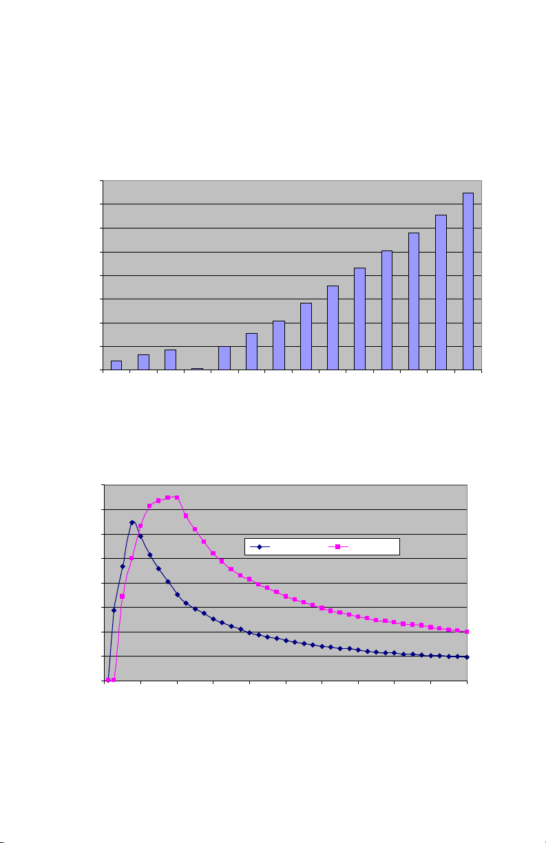
Output Power versus Setting at 200 Ohm Load
Output Power (Cut) versus Load Resistance
Output power at each set point with specied load resistance (per IEC 606012-2, sub clause 6.8.3) is given in the graphs below.
Output Power versus Setting at 200ohms Resistive Load
400
350
300
250
200
Power (W)
150
100
DRAFT
50
0
Coag1Coag2Coag31 2 3 4 5 6 7 8 9 10 11
Cut Leve l
Output Power (CUT) versus Load Resistance
400
350
300
250
200
(Power (W)
150
100
50
Half Setting Full Setting
0
0 100 200 300 400 500 600 700 800 900 1000
EN-50
Load Resistance (ohms)
Page 53
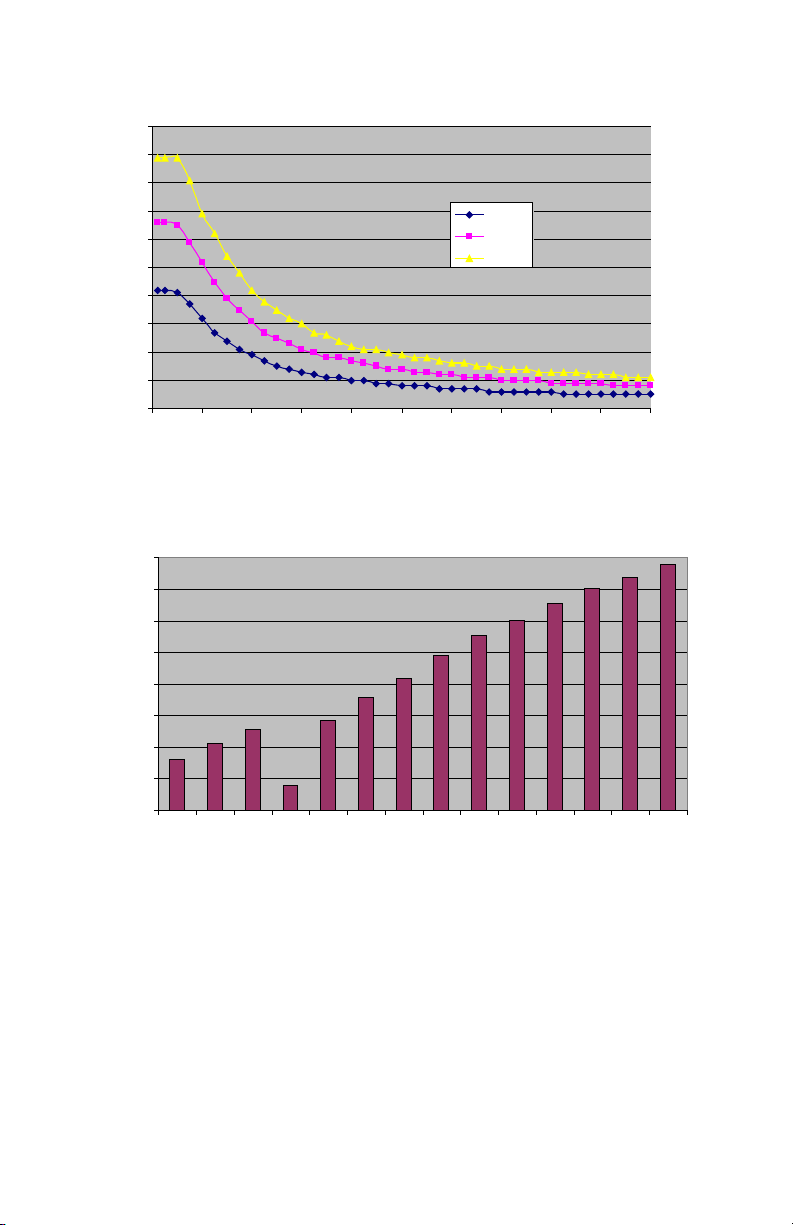
Output Power (COAG) versus Load Resistance
Output Power (Coag) versus Load Resistance
Maximum Output Voltage (RMS) versus Setting
100
90
80
70
60
50
40
Power (W)
30
20
10
0
DRAFT
0 100 200 300 400 500 600 700 800 900 1000
Load Resistance (Ohms)
Coag 1
Coag 2
Coag 3
Maximum Open Circuit Voltage versus Set Point
400
350
300
250
200
150
Voltage (Vrms)
100
50
0
Coag1Coag2Coag31 2 3 4 5 6 7 8 9 10 11
Cut Level
EN-51
Page 54

Classications
Warning This equipment is not suitable for use in the presence
of a ammable anesthetic mixture with air, oxygen, or
nitrous oxide.
• Class I equipment
• Type BF applied part
• Degree of protection against harmful ingress of water
• Generator: IEC 60601-2-2: Requirement per clause 44.3
• Probe: IEC 60601-2-2: Requirement per clause 44.6
• Footswitch: IEC 60601-2-2: Requirement per clause 44.6,
IPX7 Water-tight Equipment
Approvals
Complies with medical safety standards:
• IEC 60601-1: 1998 + A1:1991 + A2:1995
• AS 3200.1.0: 1998
• IEC 60601-1-2: 2001
• IEC 60601-2-2: 2006
• UL 60601-1: 2003
• CSA C22.2 No. 601-1-M90
DRAFT
Federal Communications Commission (FCC)
FCC ID: SSH-XFC2
Trade Name: Crossre2 Console
Type or Model: 0475100000
This device complies with Part 15 of the FCC rules. Operation is subject to
the following two conditions:
1. this device may not cause harmful interference, and
2. this device must accept any interference received, including
interference that may cause undesired operation.
Note: FCC regulations provide that changes or modications not expressly
approved by Stryker Endoscopy could void your authority to operate this
equipment.
Frequency of transmission: 13.56MHz
Type of frequency / characteristics of the modulation: 10% ASK
Subcarrier: 423.75kHz, Manchester coding
Eective radiated power: 50μW
EN-52
Page 55

Industry Canada (IC)
IC: 4919C-XFC2
Trade Name: Crossre2 Console
Type or Model: 0475100000
Operation is subject to the following two conditions: (1) this device may
not cause interference, and (2) this device must accept any interference,
including interference that may cause undesired operation of the device.
The term “IC” before the radio certication number only signies that
Industry Canada technical specications were met.
DRAFT
EN-53
Page 56

R&TTE Declaration of Conformity (DoC)
We,
Declare under our sole responsibility that the product:
to which this declaration relates is in conformity with the essential
requirements and other relevant requirements of the R&TTE Directive
(1999/5/EC).
e product is compliant with the following standards and/or other
normative documents:
Name of company: Stryker Endoscopy
Address: 5900 Optical Court, San Jose, CA 95138
Authorized representative: Jean-Yves Carentz
Contact detail of authorized representative: Stryker France,
ZAC Satolas Green Pusignan, Av. de Satolas Green, 69881
MEYZIEU Cedex, France
Product name: Crossre2 Integrated Arthroscopy System
Trade Name: Crossre2 Console
DRAFT
Type or Model: 0475100000
Relevant Supplementary Information: None
Safety: EN 60601-1:1990+A1:1993+A2:1995+A13:1996
EMC: EN 60601-1-2:2007; EN 61000-3-2:2006
Radio Spectrum: EN 300 330-1 V1.5.1
Supplementary information: none
Notied body involved: TÜV Rheinland Product Safety
(GmbH)
Technical le held by: Stryker Endoscopy
Place and date of issue (of this DoC): San Jose, CA USA,
August 2009
Signed by or for the manufacturer:
Name: K. Jerey Semone
Title: Director, Regulatory Aairs
Hereby, Stryker Endoscopy declares that this Short Range Device is in
compliance with the essential requirements and other relevant provisions of
Directive 1999/5/EC.
EN-54
Page 57

Electromagnetic Compatibility
Like other electrical medical equipment, the Crossre2 System requires
special precautions to ensure electromagnetic compatibility with other
electrical medical devices. To ensure electromagnetic compatibility (EMC),
the Crossre2 System must be installed and operated according to the EMC
information provided in this manual.
The Crossre2 System has been designed and tested to comply with IEC
60601-1-2:2001 requirements for EMC with other devices.
Warning This equipment is intended for use by health care
professionals only. This equipment may cause radio
interference or may disrupt the operation of nearby
DRAFT
equipment. It may be necessary to take mitigation
measures, such as reorienting or relocating the equipment
or shielding the location.
Portable and mobile RF communications equipment can aect the normal
function of the Crossre2 System even if such equipment meets the
applicable emissions requirements.
Do not use cables or accessories other than those provided with the
Crossre2 System, as this may result in increased electromagnetic emissions
or decreased immunity to such emissions.
If the Crossre2 System is used adjacent to or stacked with other
equipment, observe and verify normal operation of the Crossre2 System
in the conguration in which it will be used prior to using it in a surgical
procedure as interference may occur. Consult the tables below for guidance
in placing the Crossre2 System.
EN-55
Page 58

When the Crossre2 System is interconnected with other medical electrical
equipment, leakage currents may be additive. To minimize total patient
leakage current, any Type BF applied part should be used together with
other Type BF applied parts. Any Type CF applied part should be used
together with other Type CF applied parts. Ensure all systems are installed
according to the requirements of IEC 60601-1-1.
The separable AC power cord is provided as a means of emergency
shutdown and disconnection from the power source. Do not position the
console in a way that is dicult to disconnect the AC power cord.
DRAFT
Guidance and Manufacturer’s Declaration: Electromagnetic Emissions
The Crossre2 System is intended for use in the electromagnetic environment specied below. The
customer or the user of Crossre2 System should ensure that it is used in such an environment.
Emissions Test Compliance Electromagnetic Environment - Guidance
RF emissions CISPR11 Group 1 The Crossre2 System must emit
RF emissions CISPR11 Class A Crossre2 System is suitable for use in all
Harmonic emissions IEC 61000-
3-2
Voltage Fluctuations/icker
emissions IEC 61000-3-3
Class A
Complies
electromagnetic energy in order to
perform its intended function. Nearby
electronic equipment may be aected.
establishments other than domestic and
those directly connected to the public
low-voltage power supply network that
supplies buildings used for domestic
purposes.
EN-56
Page 59

Guidance and Manufacturer’s Declaration: Electromagnetic Immunity
The Crossre2 System is intended for use in the electromagnetic environment specied below. The
customer or the user of Crossre2 System should ensure that it is used in such an environment
Immunity Test IEC 60601 Test Level Compliance Level Electromagnetic
Electrostatic
Discharge (ESD) IEC
61000-4-2
Electrical fast
transient/burst IEC
61000-4-4
Surge
IEC 61000-4-5
Voltage dips, short
interruptions and
voltage variations
on power supply
input lines IEC
61000-4-11
Power frequency
(50/60Hz) magnetic
eld IEC 61000-4-8
DRAFT
NOTE: Ut is the a.c. mains voltage prior to application of the test level.
±6kV contact
±8kV air
±2kV for power supply
lines ±1kV for input/
output lines
±1kV dierential mode
±2kV common mode
<5% Ut (>95% dip in Ut)
for 0.5 cycle
40% Ut (60% dip in Ut) for
5 cycles
70% Ut (30% dip in Ut) for
25 cycles
<5% Ut (>95% dip in Ut)
for 5 sec.
3 A/m N/A Power-frequency
±2,4,6kV contact ±2,4,8kV
air
±2kV for power supply
lines ±1kV for input/
output lines
±0.5, 1kV dierential
mode ±1, 2kV common
mode
<5% Ut (>95% dip in Ut)
for 0.5 cycle
40% Ut (60% dip in Ut)
for 5 cycles
70% Ut (30% dip in Ut) for
25 cycles
<5% Ut (>95% dip in Ut)
for 5 sec.
Environment: Guidance
Floors should be wood,
concrete, or ceramic tile.
If oors are covered with
synthetic material, the
relative humidity should
be at least 30%.
Mains power quality
should be that of a typical
commercial or hospital
environment.
Mains power quality
should be that of a typical
commercial or hospital
environment.
Mains power quality
should be that of a typical
commercial or hospital
environment. If the user
of Crossre2 System
requires continued
operation during power
mains interruptions,
it is recommended
that Crossre2 System
be powered from an
uninterruptible power
supply or a battery.
magnetic elds should
be at levels characteristic
of a typical location in
a typical commercial or
hospital environment.
EN-57
Page 60
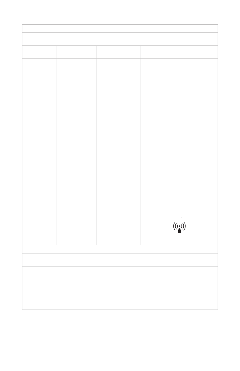
Guidance and Manufacturer’s Declaration: Electromagnetic Immunity
Crossre2 System is intended for use in the electromagnetic environment specied below. The customer or
Immunity Test IEC 60601 Test
the user of Crossre2 System should ensure that it is used in such an environment.
Level
Compliance Level Electromagnetic Environment: Guid-
ance
Portable and mobile RF communications
equipment should be used no
closer to any part of the Crossre2
system, including its cables, than the
recommended separation distance
calculated from the equation applicable
to the frequency of the transmitter.
Recommended Separation Distance d
= 1.17 √P
Conducted RF
IEC 61000-4-6
Radiated RF IEC
61000-4-3
NOTE 2: These guidelines may not apply in all situations. Electromagnetic propagation is aected by
(a) Field strengths from xed transmitters, such as base stations for radio (cellular/cordless) telephones
and land mobile radios, amateur radio, AM and FM radio broadcast, and T V broadcast, cannot be predicted
theoretically with accuracy. To assess the electromagnetic environment due to xed RF transmitters, an
electromagnetic site survey should be considered. If the measured eld strength in the location in which the
Crossre2 System is used exceeds the applicable RF compliance level above, the Crossre2 System should
be observed to verify normal operation. If abnormal performance is observed, additional measures may be
(b) Over the frequency range 150 kHz to 80 MHz, eld strengths should be less than 3 V/m.
3 Vrms 150 kHz to
80 MHz
DRAFT
3 V/m
80MHz to 2.5 GHz
NOTE 1: At 80 MHz and 800 MHz, the higher frequency range applies.
absorption and reection from structures, objects, and people.
necessary, such as reorienting or relocating the Crossre2 System.
3 V d = 1.17 √P
80 MHz to 800 MHz
3 V/m d = 2.33 √P
80 MHz to 2.5 GHz
where P is the maximum output
power rating of the transmitter in
watts (W) according to the transmitter
manufacturer and d is the recommended
separation distance in meters (m).
Field strengths from xed RF
transmitters, as determined by an
electromagnetic site survey (a), should
be less than the compliance level in each
frequency range(b).
Interference may occur in the vicinity of
equipment marked with the following
symbol:
EN-58
Page 61
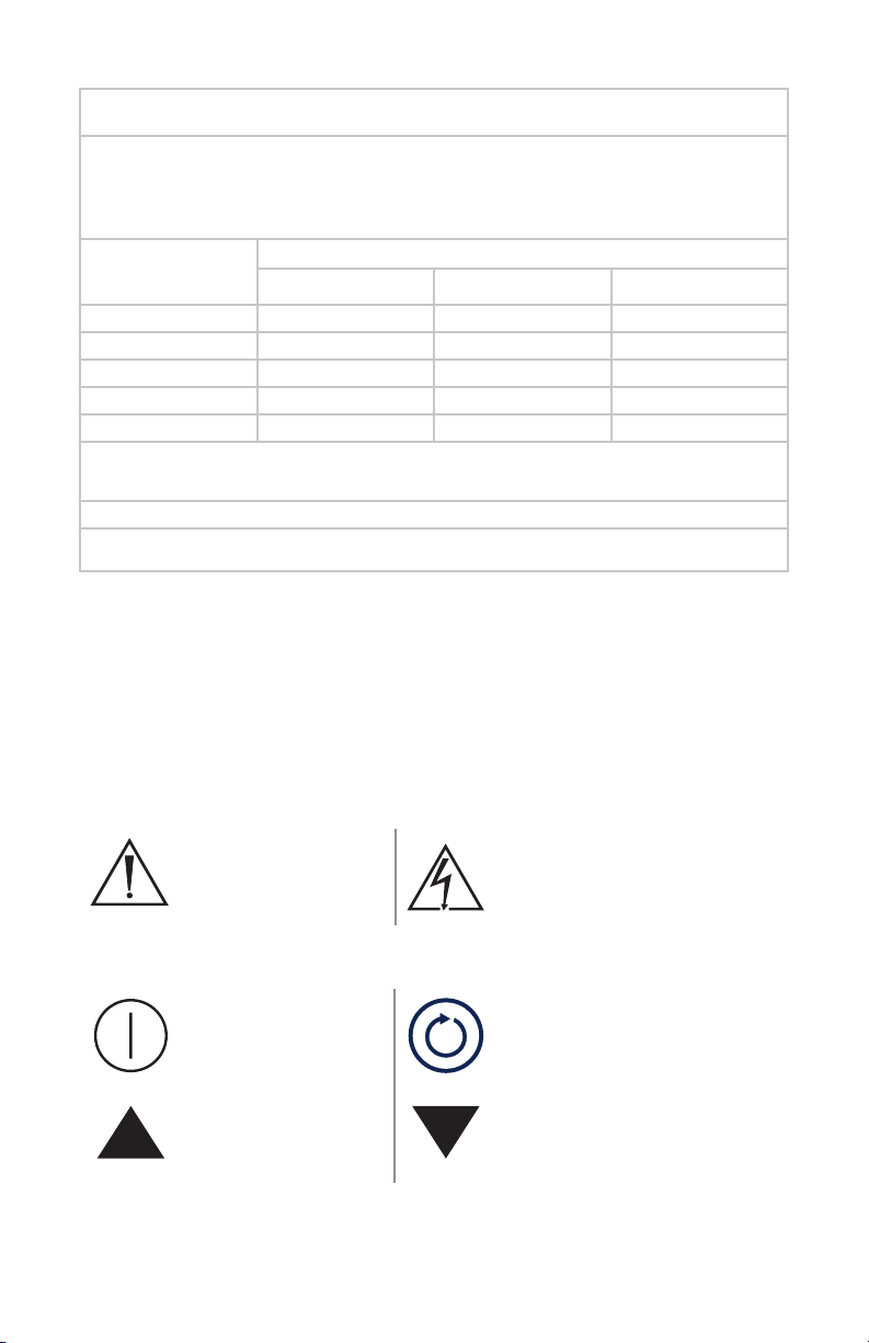
Recommended Separation Distances Between Portable and Mobile RF Communications Equipment
The Crossre2 System is intended for use in an electromagnetic environment in which radiated RF
disturbances are controlled. The user of the Crossre2 System can help prevent electromagnetic
interference by maintaining a minimum distance between portable and mobile RF communications
equipment (transmitters) and the Crossre2 System as recommended below, according to the maximum
Rated maximum
output power (W) of
transmitter
0.01 0.12 0.12 0.23
0.1 0.37 0.37 0.74
1 1.17 1.17 3.70
10 3.70 2.33 7.37
100 11.70 11.70 23.30
For transmitters rated at a maximum output power not listed above, the recommended separation distance (d) in meters (m)
can be estimated using the equation applicable to the frequency of the transmitter, where P is the maximum output power
NOTE 2: These guidelines may not apply in all situations. Electromagnetic propagation is aected by absorption and reection
DRAFT
NOTE 1: At 80 MHz and 800 MHz, the separation distance for the higher frequency range applies.
output power of the communications equipment.
rating of the transmitter in watts (W) according to the transmitter manufacturer.
and the Crossre2 System
Separation distance (m) according to frequency of transmitter
150 kHz to 80 MHz 80 MHz to 800 MHz 800 MHz to 2.5 GHz
from structures, objects, and people.
Symbol Glossary
This device and its labeling contain symbols that provide important
information for the safe and proper use of the device. These symbols are
dened below.
Warning Symbols
Warning/Caution:
See instructions for
use
Front Console Symbols
Power Select
Up Down
Hazardous voltage present
EN-59
Page 62
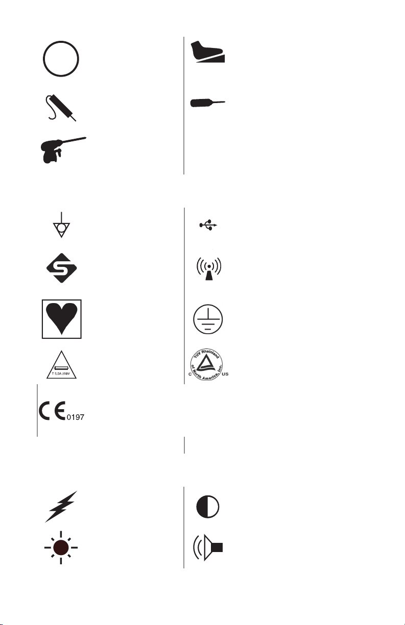
MENU
Rear Console Symbols
Menu Footswitch
Probe Shaver handpiece
Directed energy
handpiece
DRAFT
Equipotentiality USB
Stryker rewire Emits RF radiation
Type CF rated Protective ground earth
Fuse rating
Fullls requirements
of the European
Medical Device
Directive 93/42/EEC
LCD Symbols
Electrosurgical unit Contrast
Brightness Sound
EN-60
Compliant to CSA C22.2 No.
601.1-M90, and UL 601-1
Page 63
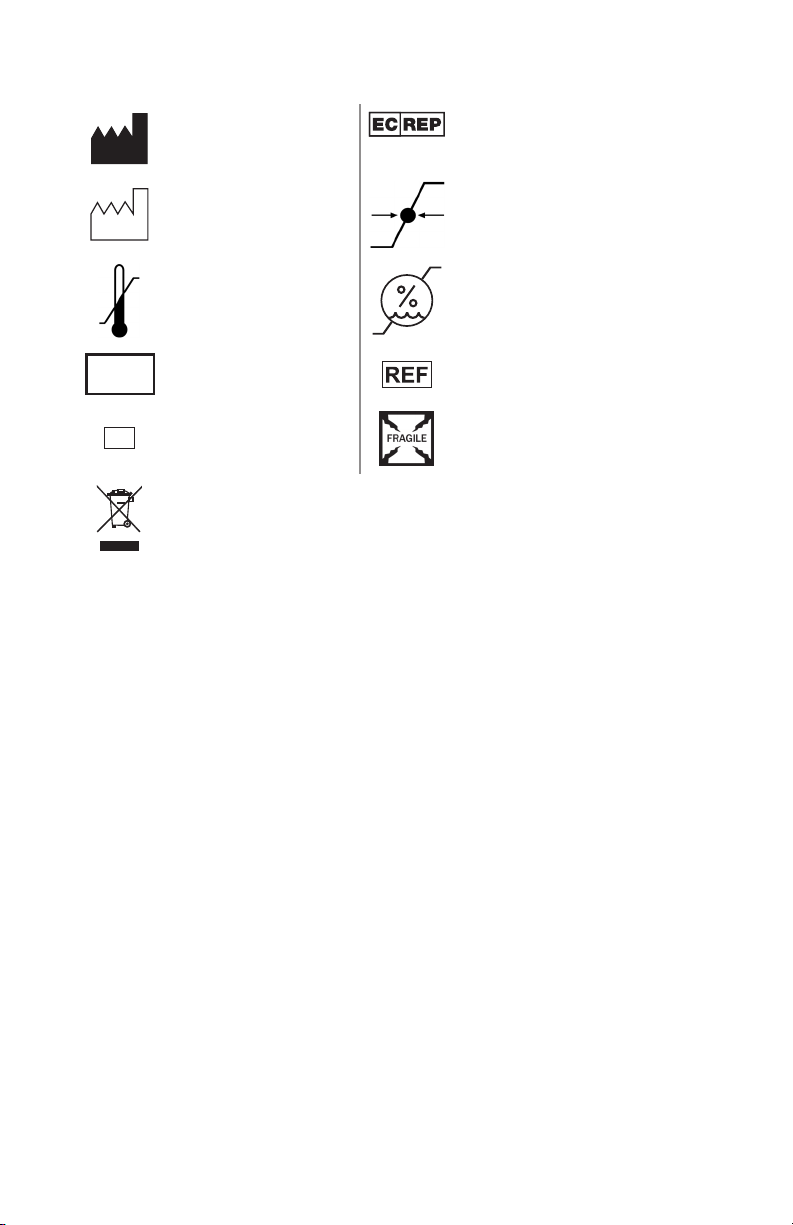
Packaging/Labeling Symbols
LOT
SN
Legal manufacturer
Date of manufacture Atmospheric pressure range
Ambient
temperature range
Lot number
Authorized representative in
Europe
Relative humidity range
Product number
DRAFT
Serial number Fragile
This product contains electrical waste or electronic equipment.
It must not be disposed of as unsorted municipal waste and
must be collected separately.
EN-61
Page 64

DRAFT
EN-62
Page 65

Page 66
DRAFT
Stryker Endoscopy
5900 Optical Court
San Jose, CA 95138 USA
1-408-754-2000, 1-800-624-4422
www.stryker.com
European Representative:
Regulatory Manager, Stryker France
ZAC Satolas Green Pusignan
Av. De Satolas Green
69881 MEYZIEU Cedex, France
P13827 dra 2
2011/10
 Loading...