

Page 1
Michael Graves with Stryker Bedside Cabinet
Table de chevet Michael Graves de Stryker
4821
Operations/Maintenance Manual
Manuel d’utilisation et d’entretien
2013/02 C.1 4821-009-001 REV C www.stryker.com
Page 2

Page 3

Table of Contents
Symbols and Definitions ...................................................................1-2
Symbols ...........................................................................1-2
Warning/Caution/Note Definition..........................................................1-2
Introduction ............................................................................1-3
Intended Use ........................................................................1-3
Product Description ...................................................................1-3
Specifications .......................................................................1-3
Contact Information ...................................................................1-4
Serial Number Location ................................................................1-4
Summary of Safety Precautions .............................................................1- 5
Operation Guide.........................................................................1-6
Raising the Drop Leaf .................................................................1- 6
Lowering the Drop Leaf ................................................................1-6
Removing the Wastebasket .............................................................1-6
Installing the Wastebasket ..............................................................1- 6
Preventative Maintenance..................................................................1-7
Checklist ...........................................................................1-7
Cleaning...............................................................................1-7
Quick Reference Replacement Parts List ......................................................1- 8
Service Information.......................................................................1-9
Drop Leaf Replacement ................................................................1- 9
Drop Leaf Hinge Replacement ...........................................................1-9
Drawer Front and Strap Pull Replacement ..................................................1-9
Drawer Slide Replacement .............................................................1-10
Base Cover Replacement..............................................................1-10
Caster Replacement .................................................................1-1 1
Hospitality Handle Replacement .........................................................1-1 1
Bedside Cabinet Assembly ................................................................1-12
Base Assembly.........................................................................1-14
Cabinet Assembly.......................................................................1-15
Top Assembly..........................................................................1-16
Drawer Assembly .......................................................................1-17
Warranty .............................................................................1-18
Three Year Warranty .................................................................1-18
To Obtain Parts and Service ...........................................................1-18
Return Authorization..................................................................1-18
Damaged Merchandise ...............................................................1-18
International Warranty Clause...........................................................1-18
EnglishEnglish
www.stryker.com 4821- 009-0 01 REV C 1-1
Page 4
Symbols and Definitions
English
SYMBOLS
Warning/Caution: Consult accompanying documentation
Safe Working Load
Pinch Point
Manufacturer
WARNING/CAUTION/NOTE DEFINITION
The words WARNING, CAUTION and NOTE carry special meanings and should be carefully reviewed.
WARNING
Alerts the reader about a situation which, if not avoided, could result in death or serious injury. It may also describe
potential serious adverse reactions and safety hazards.
CAUTION
Alerts the reader of a potentially hazardous situation which, if not avoided, may result in minor or moderate injury to the
user or patient or damage to the equipment or other property. This includes special care necessary for the safe and
effective use of the device and the care necessary to avoid damage to a device that may occur as a result of use or
misuse.
NOTE
Provides special information to make maintenance easier or important instructions clearer.
Return To Table of Contents
1-2 4821- 009-0 01 REV C www.stryker.com
Page 5
Introduction
This manual is designed to assist you with the operation of Model 4821 Michael Graves with Stryker Bedside Cabinet.
Read this manual thoroughly before using the equipment or beginning maintenance on it. To ensure safe operation of
this equipment, it is recommended that methods and procedures be established for educating and training staff on the
safe operation of this unit.
INTENDED USE
The Model 4821 Michael Graves with Stryker Bedside Cabinet is a wheeled bedside storage unit. This product is to be
used for storage of patient or caregiver items. The bedside cabinet is not to be used for medical procedures.
PRODUCT DESCRIPTION
The Stryker Model 4821 Bedside Cabinet features a disposable storage bin, removable trash bin and a stowable dropleaf top for the storage of patient or caregiver items.
SPECIFICATIONS
Safe Working Load, Total Unit 150 lb 68 kg
EnglishEnglish
Safe Working Load, Bottom Tray 68 lb 31 kg
Safe Working Load, Cabinet Shelf 35 lb 16 kg
Safe Working Load, Drawer 19 lb 9 kg
Safe Working Load, Drop Leaf 25 lb 11 kg
Maximum Width (with wastebasket and stowed drop leaf)
Length 21 in 53 cm
Height (to top of the hospitality handle) 39.75 in 101 cm
Weight 72.5 lb 33 kg
Stryker reserves the right to change specifications without notice.
27.75 i n 70.5 cm
WARNING
Do not transport the bedside cabinet over obstacles with weight on the drop leaf. Remove all items to avoid the risk of
injury to the individual or damage to the unit.
www.stryker.com 4821- 009-0 01 REV C 1-3
Return To Table of Contents
Page 6
Introduction
English
CONTACT INFORMATION
Contact Stryker Customer Service or Technical Support at: (800) 327-0770 or (269) 324-6500.
Stryker Medical
3800 E. Centre Avenue
Portage, MI 49002
USA
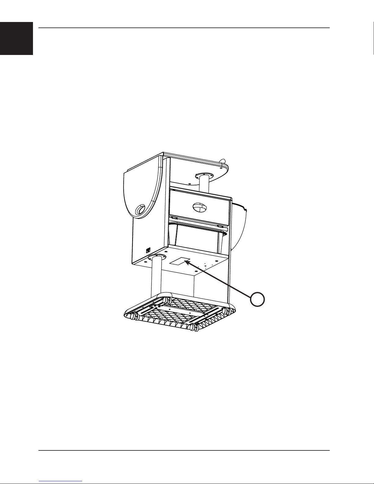
Please have the serial number (A) of your Stryker product available when calling Stryker Customer Service or Technical
Support. Include the serial number in all written communication.
SERIAL NUMBER LOCATION
A
Return To Table of Contents
1-4 4821- 009-0 01 REV C www.stryker.com
Page 7
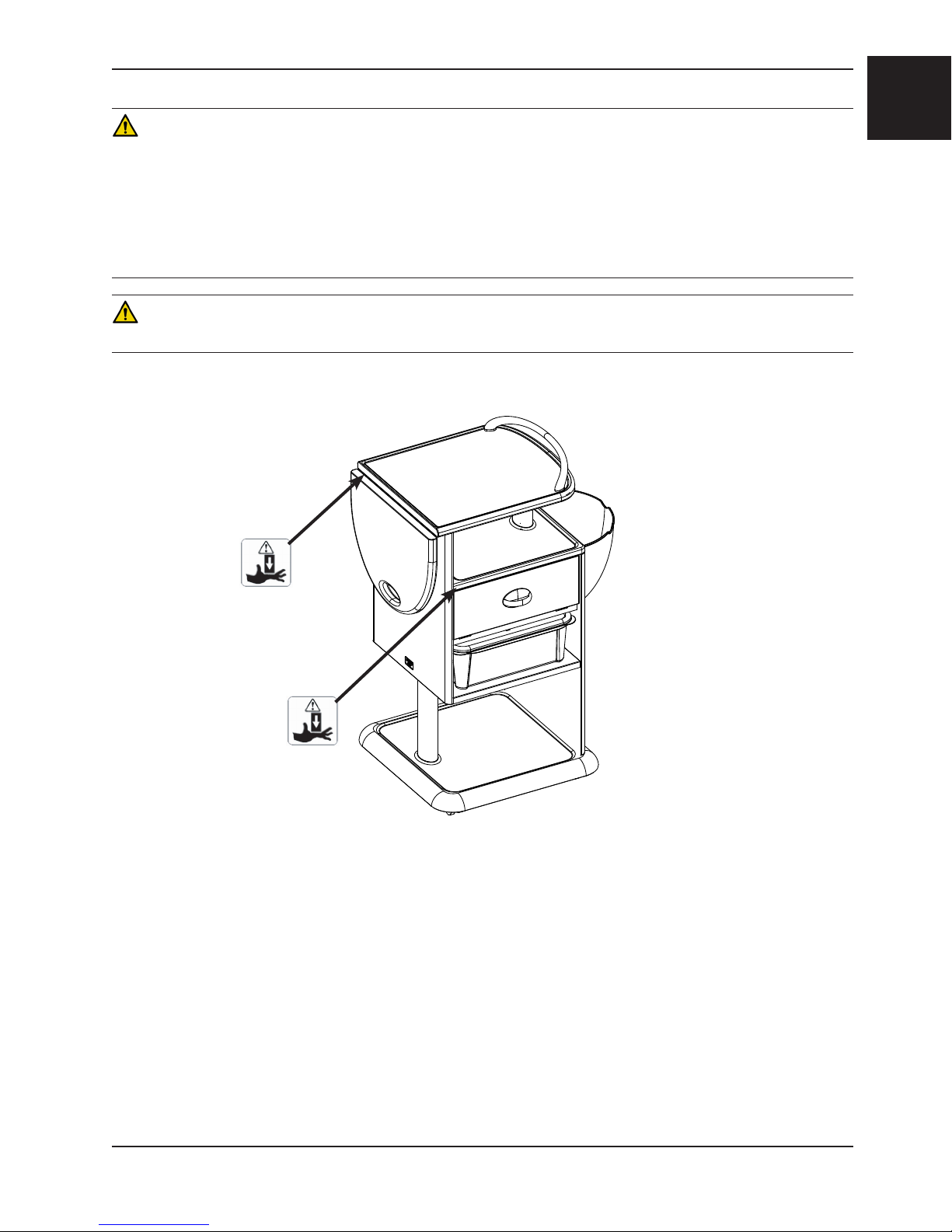
Summary of Safety Precautions
WARNING
• Do not sit on the bedside cabinet. Sitting on the bedside cabinet may cause the stand to tip which may result in
injury to the individual or damage to the unit.
• Use caution when raising and lowering the drop leaf to avoid pinching your fingers between the drop leaf and
support arm, cabinet, and/or unit top.
• Use caution when opening and closing drawers to avoid pinching your fingers between the drawer and cabinet.
• Do not transport the bedside cabinet over obstacles with weight on the drop leaf. Remove all items to avoid the risk
of injury to the individual or damage to the unit.
CAUTION
Failure to properly clean a contaminated surface will increase the risk of exposure to bloodborne pathogens.
EnglishEnglish
www.stryker.com 4821- 009-0 01 REV C 1-5
Return To Table of Contents
Page 8
English
Operation Guide
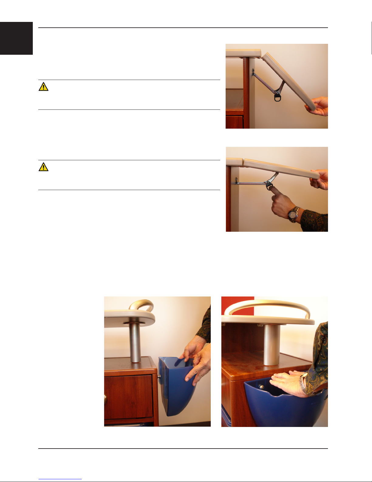
RAISING THE DROP LEAF
To raise the drop leaf, lift the drop leaf by the end handle until the support
arm locks into place as shown in Figure 1.
WARNING
Use caution when raising and lowering the drop leaf to avoid pinching your
fingers between the drop leaf and support arm, cabinet, and/or unit top.
LOWERING THE DROP LEAF
To lower the drop leaf, pull the support arm ring (Figure 2) to release and
lower the drop leaf down to vertical.
Figure 1: Raise Drop Leaf
WARNING
Use caution when raising and lowering the drop leaf to avoid pinching your
fingers between the drop leaf and support arm, cabinet, and/or unit top.
REMOVING THE WASTEBASKET
To remove the wastebasket, remove all items, then lift up on both corners
on the back edge of the wastebasket until it releases from the two knobs
as shown in Figure 3.
Figure 2: Lower Drop Leaf
INSTALLING THE WASTEBASKET
To install the wastebasket, place the keyhole slots of the wastebasket over the two knobs and push down on top edge
until it snaps into place as shown in Figure 4.
Note: The wastebasket
is not intended for fluids.
Figure 3: Remove Wastebasket Figure 4: Install Wastebasket
Return To Table of Contents
1-6 4821- 009-0 01 REV C www.stryker.com
Page 9

Preventative Maintenance
Preventative maintenance should be performed at a minimum of annually. A preventative maintenance program should
be established for all Stryker Medical equipment. Preventative maintenance may need to be performed more frequently
based on the usage level of the product.
CHECKLIST
_____ All fasteners secure
_____ Top and laminate intact - not damaged
_____ Top edge molding intact - not damaged
_____ Drop leaf attachment intact - not damaged
_____ Drawer operates properly
_____ No debris in casters and they roll/swivel freely
Unit Serial Number:
EnglishEnglish
Completed by: ____________________________________________ Date: _____________________
Cleaning
A recommended cleaner is a chlorinated bleach solution (5.25% - less than 1 part bleach to 100 parts water). Thoroughly
rinse the solution from the product surface. If other hospital-grade cleaning agents are used, follow the instructions
provided by the cleaning solution’s manufacturer. Do not allow cleaning solutions or other fluids to pool on the unit.
Wipe the surface with a soft, dry cloth to remove any moisture.
CAUTION
Failure to properly clean a contaminated surface will increase the risk of exposure to bloodborne pathogens.
www.stryker.com 4821- 009-0 01 REV C 1-7
Return To Table of Contents
Page 10

English
Quick Reference Replacement Parts List
The parts and accessories listed on this page are all currently available for purchase. Some of the parts identified on
the assembly drawing parts in this manual may not be individually available for purchase. Please call Stryker Customer
Service USA at 1-800-327-0770 for availability and pricing.
Part Name Part Number
Base Cover, Dark Gray 4821-100-012
Base Cover, Stone 4821-100-013
Caster 3150-001-200
Drawer Box 4821-400-010
Drop Leaf Hinge 4821-300-030
Kit, Bracket 4821-700-030
Kit, Caster 4821-700-040
Kit, Drawer Front, Windsor Mahogany 4821-70 0 -150
Kit, Drawer Front, Manitoba Maple 4821-700 -160
Kit, Drawer Front, Antique Whitewash 4821-700-170
Kit, Drawer Front, Pearwood 4821-700 -180
Kit, Drawer Slide 4821-700-190
Kit, Drop Leaf Support 4821-700-020
Kit, Drop Leaf, Stony Ground 4821-70 0-110
Kit, Drop Leaf, Charleston Gray 4821-700 -120
Kit, Hinge 4821-700-130
Kit, Hospitality Handle 4821-700-140
Kit, Take Home Bin 4821-700-010
Kit, Tall Column 4821-700-050
Kit, Upper Top, Mahogany - Charleston Gray 4821-700-070
Kit, Upper Top, Western Iron - Stony Ground 4821-700-080
Kit, Upper Top, Frosty White - Charleston Gray 4821-700-090
Kit, Upper Top, Frosty White - Stony Ground 4821-700-100
Kit, Wastebasket Knob 4821-700-060
Strap Pull 4820-200-010
Wastebasket 4821-000-010
Return To Table of Contents
1-8 4821- 009-0 01 REV C www.stryker.com
Page 11

Service Information
DROP LEAF REPLACEMENT
Tools Required:
• #2 Phillips Screwdriver
Procedure:
1. Using a #2 Phillips screwdriver, remove the two screws that secure the drop leaf support to the drop leaf.
2. Using a #2 Phillips screwdriver, remove the seven screws that secure the drop leaf to the hinge.
Note: Hold the drop leaf to support it while removing the screws.
3. Reverse steps to reinstall.
4. Verify proper operation of the unit before returning it to service.
DROP LEAF HINGE REPLACEMENT
Tools Required:
• #2 Phillips Screwdriver
EnglishEnglish
Procedure:
1. Using a #2 Phillips screwdriver, remove the two screws that secure the drop leaf support to the drop leaf.
2. Using a #2 Phillips screwdriver, remove the seven screws that secure the drop leaf to the hinge. Set the drop leaf
aside.
Note: Hold the drop leaf to support it while removing the screws.
3. Using a #2 Phillips screwdriver, remove the seven screws that secure the hinge to the cabinet assembly.
4. Reverse steps to reinstall.
5. Verify proper operation of the unit before returning it to service.
DRAWER FRONT AND STRAP PULL REPLACEMENT
Tools Required:
• #2 Phillips Screwdriver
Procedure:
1. Open the drawer midway.
2. Using a #2 Phillips screwdriver, remove the two screws, located on the inside of the drawer box, that secure the
drawer front to the drawer.
3. Using a #2 Phillips screwdriver, remove the two screws that secure the strap pull handle to the drawer.
4. Reverse steps to reinstall.
5. Verify proper operation of the unit before returning it to service.
www.stryker.com 4821- 009-0 01 REV C 1-9
Return To Table of Contents
Page 12

English
Service Information
DRAWER SLIDE REPLACEMENT
Tools Required:
• #2 Phillips Screwdriver
Procedure:
1. Push the drawer out to access the drawer slide screws.
2. Using a #2 Phillips screwdriver, remove the two screws that secure the drawer slides to the cabinet shelf.
3. Push the drawer in to access the drawer slide screws.
4. Using a #2 Phillips screwdriver, remove the two screws that secure the drawer slides to the cabinet shelf on the
opposite side.
5. Remove the drawer assembly from the cabinet.
6. Flip the drawer assembly upside down.
7. Using a #2 Phillips screwdriver, remove the four screws (two screws on each drawer slide) that secure the slide
to the drawer box.
8. Reverse steps to reinstall.
9. Verify proper operation of the unit before returning it to service.
BASE COVER REPLACEMENT
Tools Required:
• T27 Torx Driver
• #2 Phillips Screwdriver
Procedure:
1. Empty and remove the wastebasket by lifting up on both corners on the back edge until it releases from the two
knobs. Set the wastebasket aside for reinstallation.
2. Tilt the table on its side while keeping the drop leaf facing up.
Note: Place something on the floor to protect the bedside cabinet.
3. Using a T27 Torx driver, remove the four bolts that secure the column to the base assembly.
4. Using a #2 Phillips screwdriver, remove the four bolts that secure the wooden side panel to the base assembly.
5. Using a #2 Phillips screwdriver, remove the six screws that secure the base weldment to the base cover.
6. Reverse steps to reinstall.
7. Verify proper operation of the unit before returning it to service.
Return To Table of Contents
1-10 4821- 009-0 01 REV C www.stryker.com
Page 13

Service Information
CASTER REPLACEMENT
Tools Required:
• Drill
• 3/16” Drill Bit
• Pop Rivet Gun with 3/16” Tip
Procedure:
1. Empty and remove the wastebasket by lifting up on both corners on the back edge until it releases from the two
knobs. Set the wastebasket aside for reinstallation.
2. Tilt the table on its side while keeping the drop leaf facing up.
Note: Place something on the floor to protect the bedside cabinet.
3. Using a drill with a 3/16” drill bit, remove the two rivets that secure the caster to the base weldment.
4. Using a pop rivet gun with a 3/16” tip, install two new pop rivets (0025-122-000) to secure the caster to the base
weldment.
5. Reverse steps to reinstall.
6. Verify proper operation of the unit before returning it to service.
HOSPITALITY HANDLE REPLACEMENT
EnglishEnglish
Tools Required:
• #2 Phillips Screwdriver
Procedure:
1. Using a #2 Phillips screwdriver, remove the two flat head machine screws that secure the hospitality handle to the
cabinet. Discard the handle and both screws.
2. Using a #2 Phillips screwdriver, install two new flat head machine screws to secure the hospitality handle to the
cabinet.
3. Reverse steps to reinstall.
4. Verify proper operation of the unit before returning it to service.
www.stryker.com 4821- 009-0 01 REV C 1- 11
Return To Table of Contents
Page 14

English
Bedside Cabinet Assembly
4821-010-010 Rev G (Reference Only)
C
K
K
Torque item K to
9 ± 2 in-lb
G
Torque item M to
15 ± 5 in-lb
P
H
J
L
M
B
A
N
E
D
R
F
Return To Table of Contents
1-12 4821-009 - 001 REV C www.stryker.com
Page 15

Bedside Cabinet Assembly
Item Description Qty. 4821-010-011
Windsor
Mahogany/
Frosty White
A Base Assembly
(page 1-14)
B Cabinet
Assembly
(page 1-15)
C Top Assembly
(page 1-16)
D Drawer
Assembly
(page 1-17)
E Wastebasket 1 4821-000-010 4821-000-010 4821-000-010 4821-000-010 4821-000-010
F Take Home Bin 1 4821-000-020 4821-000-020 4821-000-020 4821-000-020 4821-000-020
G 8” Drop Leaf
Support
H Bracket 1 4820-100-015 4820-100-015 4820-100-015 4820-100-015 4820-100-015
J Wood Dowel 4 0058-138-000 0058-138-000 0058-138-000 0058-138-000 0058-138-000
K Pan Head
Tapping Screw
L Flat Head
Machine Screw
M Flat Head Set
Machine Screw
N Pan Head
Machine Screw
P Pan Head
Tapping Screw
R Screw 4 0020-022-000 0020-022-000 0020-022-000 0020-022-000 0020-022-000
1 4821-110 -012 * 4821-110- 013* 4821-110- 013* 4821-110 -012 * 4821-110- 012*
1 4821-210-011* 4821-210-012* 4821-210-013* 4821-210-014* 4821-210-013*
1 4821-310-013* 4821-310-014* 4821-310-012* 4821-310-013* 4 82 1-310- 011*
1 4821- 410- 011* 4821- 410-012* 4821-410-013* 4821-410 - 014* 4821-410-013*
1 4821-300-050 4821-300-050 4821-300-050 4821-300-050 4821-300-050
10 0050-077-000 0050-077-000 0050-077-000 0050-077-000 0050-077-000
4 0001-208-000 0001-208-000 0001-208-000 0001-208-000 0001-208-000
4 0023-334-000 0023-334-000
4 0050-080-000 0050-080-000 0050-080-000 0050-080-000 0050-080-000
2 0023-116-000 0023-116-000 0023-116-000 0023-116-000 0023-116-000
4821-010-012
Manitoba
Maple/Frosty
White
4821-010-013
Antique
Whitewash/
Western Iron
0023-334-000 0023-334-000 0023-334-000
4821-010-014
Pearwood/
Frosty White
4821-010-015
Antique
Whitewash/
Windsor
Mahogany
EnglishEnglish
* Shown for reference only. These assemblies are not available for sale.
www.stryker.com 4821- 009-0 01 REV C 1-13
Return To Table of Contents
Page 16

Base Assembly
English
4821-110-010 Rev B (Reference Only)
J
G
F
H
D
C
B
4821-110 -012
Pearwood/
Frosty White
4821-110 -012
Antique
Whitewash/
Windsor
A
Item Description Qty. 4821-110 -012
Windsor
Mahogany/
Frosty White
E
4821-110 -013
Manitoba
Maple/Frosty
White
4821-110 -013
Antique
Whitewash/
Western Iron
Mahogany
A Base Cover 1 4821-100-012 4821-100-013 4821-100-013 4821-100-012 4821-100-012
B Base Weldment 1 4821-110-020 4821-110-020 4821-110-020 4821-110-020 4821-110-020
C Caster 4 3150-001-200 3150-001-200 3150-001-200 3150-001-200 3150-001-200
D Pop Rivet 8 0025-122-000 0025-122-000 0025-122-000 0025-122-000 0025-122-000
E Tapping Screw 4 0023-260-000 0023-260-000 0023-260-000 0023-260-000 0023-260-000
F Column, Taller 1 4821-100-040 4821-100-040 4821-100-040 4821-100-040 4821-100-040
G Adapter Plate 1 4820-400-010 4820-400-010 4820-400-010 4820-400-010 4820-400-010
H Pan Head
4 0050-079-000 0050-079-000 0050-079-000 0050-079-000 0050-079-000
Machine Screw
J Flat Head Screw 2 0001-163-000 0001-163-000 0001-163-000 0001-163-000 0001-163-000
Return To Table of Contents
1-14 4821- 009-0 01 REV C www.stryker.com
Page 17

Cabinet Assembly
4821-210-010 Rev C (Reference Only)
A
N
M
J
Torque item L to
9 ± 2 in-lb
L
E
F
C
EnglishEnglish
B
K
G
D
H
P
Item Description Qty. 4821-210-011
Windsor
Mahogany/
Frosty White
4821-210-012
Manitoba
Maple/Frosty
White
4821-210-013
Antique
Whitewash/
Western Iron
4821-210-014
Pearwood/
Frosty White
4821-210-013
Antique
Whitewash/
Windsor
Mahogany
A Upper Side Panel 1 4821-200-011* 4821-200-012* 4821-200-013* 4821-200-014* 4821-200-013*
B Main Top 1 4821-200-021* 4821-200-022* 4821-200-023* 4821-200-024* 4821-200-023*
C Bottom Shelf 1 4821-200-031* 4821-200-032* 4821-200-033* 4821-200-034* 4821-200-033*
D Lower Side Panel 1 4821-200-041* 4821-200-042* 4821-200-043* 4821-200-044* 4821-200-043*
E Mid Shelf 1 4821-200-051* 4821-200-052* 4821-200-053* 4821-200-054* 4821-200-053*
F Shelf Support 2 4821-200-061* 4821-200-062* 4821-200-063* 4821-200-064* 4821-200-063*
G Wastebasket
2 4821-200-070 4821-200-070 4821-200-070 4821-200-070 4821-200-070
Knob
H Cam 12 3100-052-732* 3100-052-732* 3100-052-732* 3100-052-732* 3100-052-732*
J Dowel Pin 12 3100-052-733* 3100-052-733* 3100-052-733* 3100-052-733* 3100-052-733*
K Machine Screw 2 0001-207-000 0001-207-000 0001-207-000 0001-207-000 0001-207-000
L Machine Screw 4 0023-335-000* 0023-335-000* 0023-335-000* 0023-335-000* 0023-335-000*
M Wood Dowel 32 0058-138-000* 0058-138-000* 0058-138-000* 0058-138-000* 0058-138-000*
N Emblem Badge 1 4820-100-090* 4820-100-090* 4820-100-090* 4820-100-090* 4820-100-090*
P Label, Cleaning 1 4400-009-100* 4400-009-100* 4400-009-100*
4400-009-100* 4400-009-100*
* Shown for reference only. These assemblies are not available for sale.
www.stryker.com 4821- 009-0 01 REV C 1-15
Return To Table of Contents
Page 18

Top Assembly
English
4821-310-010 Rev B (Reference Only)
B
F
A
C
G
D
H
Torque item K to
15 ± 5 in-lb
J
K
L
Torque item L to
15 ± 5 in-lb
E
Torque item J to
9 ± 2 in-lb
Item Description Qty. 4821-310 - 013
Windsor
Mahogany/
Frosty White
4821-310-014
Manitoba
Maple/Frosty
White
4821-310 - 012
Antique
Whitewash/
Western Iron
4821-310-013
Pearwood/
Frosty White
4821- 310 -011
Antique
Whitewash/
Windsor
Mahogany
A Upper Top 1 4821-310-023 4821-310-024 4821-310-022 4821-310-023 4821-310-021
B Drop Leaf 1 4821-300-011 4821-300-014 4821-300-014 4821-300-011 4821-300-011
C Hinge 1 4821-300-030 4821-300-030 4821-300-030 4821-300-030 4821-300-030
D Adapter Plate 1 4820-400-010 4820-400-010 4820-400-010 4820-400-010 4820-400-010
E Column, Shorter 1 4820-400-020 4820-400-020 4820-400-020 4820-400-020 4820-400-020
F Hospitality
1 4821-300-020 4821-300-020 4821-300-020 4821-300-020 4821-300-020
Handle
G Flat Head Screw 2 0001-163-000 0001-163-000 0001-163-000 0001-163-000 0001-163-000
H Tapping Screw 7 0023-116-000 0023-116-000 0023-116-000 0023-116-000 0023-116-000
J Tapping Screw 7 0050-077-000 0050-077-000 0050-077-000 0050-077-000 0050-077-000
K Flat Head
2 0001-207-000 0001-207-000 0001-207-000 0001-207-000 0001-207-000
Machine Screw
L Machine Screw 4 0023-334-000 0023-334-000 0023-334-000 0023-334-000 0023-334-000
Return To Table of Contents
1-16 4821-0 09 -001 REV C www.stryker.com
Page 19

4821-410-010 Rev B (Reference Only)
Torque item E to
9 ± 2 in-lb
E
Torque item F to
9 ± 2 in-lb
F
Drawer Assembly
EnglishEnglish
B
C
A
D
G
Item Description Qty. 4821- 410- 011
Windsor
Mahogany/
Frosty White
4821- 410-012
Manitoba
Maple/Frosty
White
4821- 410 - 013
Antique
Whitewash/
Western Iron
4821-410-014
Pearwood/
Frosty White
4821- 410 - 013
Antique
Whitewash/
Windsor
Mahogany
A Drawer Box 1 4821-400-010 4821-400-010 4821-400-010 4821-400-010 4821-400-010
B Drawer Front 2 4821-400-021 4821-400-022 4821-400-023 4821-400-024 4821-400-023
C Strap Pull 2 4820-200-010 4820-200-010 4820-200-010 4820-200-010 4820-200-010
D 2-Way Slide with
2 4821-000-030 4821-000-030 4821-000-030 4821-000-030 4821-000-030
Center Detent
E Set Screw 4 0023-333-000 0023-333-000 0023-333-000 0023-333-000 0023-333-000
F Machine Screw 4 0050-081-000 0050-081-000 0050-081-000 0050-081-000 0050-081-000
G Tapping Screw 4 0023-116-000 0023-116-000 0023-116-000 0023-116-000 0023-116-000
Return To Table of Contents
www.stryker.com 4821- 009-0 01 REV C 1-17
Page 20

Warranty
English
Stryker Medical stands behind the craftsmanship of our products. Providing our customers quality products is our
mission, and we pledge to do everything we can to quickly resolve any problems encountered within the terms of the
warranties listed below.
THREE YEAR WARRANTY
Stryker warrants the Michael Graves with Stryker Bedside Cabinet for three (3) years under normal use and proper
care. For three years from date of shipment, Stryker will repair or, at our option, replace defective merchandise free of
charge (parts, labor and shipping included). Note: Warranty excludes the take home bin as it is intended for single
patient use only.
The warranties listed above are void in cases of modifications, misuse, improper assembly or maintenance, accidents,
damage caused by a carrier other than Stryker Medical.
Michael Graves with Stryker products are designed for a 7 year expected service life under normal use, conditions, and
with appropriate periodic maintenance as described in the maintenance manual for each device.
Stryker makes no other warranty or representation, either expressed or implied, except as set forth herein. There is no
warranty of merchantability and there are no warranties of fitness for any particular purpose. In no event shall Stryker
be liable hereunder for incidental or consequential damages arising from or in any manner related to sales or use of
any such equipment.
TO OBTAIN PARTS AND SERVICE
Stryker products are supported by a nationwide network of dedicated Stryker Field Service Representatives. These
representatives are factory trained, available locally, and carry a substantial spare parts inventory to minimize repair
time. Simply call your local representative, or call Stryker Customer Service USA at 1-800-327−0770.
RETURN AUTHORIZATION
Merchandise cannot be returned without approval from the Stryker Customer Service Department. An authorization
number will be provided which must be printed on the returned merchandise. Stryker reserves the right to charge shipping and restocking fees on returned items. Special, modified, or discontinued, items not subject to return.
DAMAGED MERCHANDISE
ICC Regulations require that claims for damaged merchandise must be made with the carrier within fifteen (15) days of
receipt of merchandise. Do not accept damaged shipments unless such damage is noted on the delivery receipt at
the time of receipt. Upon prompt notification, Stryker will file a freight claim with the appropriate carrier for damages
incurred. Claim will be limited in amount to the actual replacement cost. In the event that this information is not
received by Stryker within the fifteen (15) day period following the delivery of the merchandise, or the damage was not
noted on the delivery receipt at the time of receipt, the customer will be responsible for payment of the original invoice
in full. Claims for any short shipment must be made within thirty (30) days of invoice.
INTERNATIONAL WARRANTY CLAUSE
This warranty reflects U.S. domestic policy. Warranty outside the U.S. may vary by country. Please contact your local
Stryker Medical representative for additional information.
Return To Table of Contents
1-18 4821-0 09 -001 REV C www.stryker.com
Page 21

Table des matières
Symboles et définitions................................................................... 2-2
Symboles ......................................................................... 2-2
Définition de « Avertissement », « Mise en garde » et « Remarque » .............................. 2-2
Introduction ........................................................................... 2-3
Utilisation prévue .................................................................... 2-3
Description du produit ................................................................ 2-3
Caractéristiques techniques ............................................................ 2-3
Coordonnées....................................................................... 2-4
Emplacement du numéro de série ....................................................... 2-4
Résumé des précautions de sécurité.........................................................2-5
Guide d’utilisation....................................................................... 2-6
Relever le plateau escamotable . . . . . . . . . . . . . . . . . . . . . . . . . . . . . . . . . . . . . . . . . . . . . . . . . . . . . . . . . 2-6
Descendre le plateau escamotable....................................................... 2-6
Retirer la poubelle ................................................................... 2-6
Installer la poubelle . . . . . . . . . . . . . . . . . . . . . . . . . . . . . . . . . . . . . . . . . . . . . . . . . . . . . . . . . . . . . . . . . . 2-6
Entretien préventif ...................................................................... 2 -7
Liste de vérification .................................................................. 2-7
Nettoyage............................................................................. 2-7
Liste de référence rapide des pièces de rechange...............................................2-8
Information relative au service .............................................................2-9
Remplacement du plateau escamotable ...................................................2-9
Remplacement de la charnière du plateau escamotable .......................................2-9
Remplacement de la partie frontale et de la poignée du tiroir ................................... 2-9
Remplacer les glissières de tiroir ........................................................2 -10
Remplacement du couvercle de la base...................................................2 -10
Remplacement des roulettes ...........................................................2-11
Remplacement de la poignée de service ..................................................2-11
Ensemble armoire de la table de chevet ......................................................2 -12
Ensemble base.........................................................................2 -14
Ensemble armoire de rangement............................................................2-15
Ensemble plateau.......................................................................2 -1 6
Ensemble tiroir .........................................................................2 -17
Garantie..............................................................................2 -18
Garantie de trois ans .................................................................2 -18
Pièces de rechange et service ..........................................................2-18
Autorisation de retour.................................................................2 -18
Produits endommagés . . . . . . . . . . . . . . . . . . . . . . . . . . . . . . . . . . . . . . . . . . . . . . . . . . . . . . . . . . . . . . . .2 -18
Clause de garantie internationale ........................................................2 -18
Français
www.stryker.com 4821- 009-0 01 REV C 2-1
Page 22

SYMBOLES
Symboles et définitions
Avertissement/Mise en garde : Consultez la documentation jointe
Français
Charge maximale de sécurité
Point de pincement
Fabricant
DÉFINITION DE « AVERTISSEMENT », « MISE EN GARDE » ET « REMARQUE »
Les rubriques AVERTISSEMENT, MISE EN GARDE, et REMARQUE ont une signification particulière et doivent faire
l’objet d’une lecture attentive.
AVERTISSEMENT
Avertit le lecteur des précautions à prendre afin d’éviter une situation présentant un risque potentiel de décès ou de
blessure grave. Peut également décrire des effets indésirables graves ou des risques d’accident.
MISE EN GARDE
Avertit le lecteur des mesures à prendre afin d’éviter une situation potentiellement dangereuse susceptible de causer
des blessures mineures ou modérées à l’utilisateur ou au patient ou d’endommager l’équipement ou d’autres biens.
Cela couvre notamment les précautions particulières à prendre afin d’assurer l’utilisation sécuritaire et efficace de
l’équipement et d’éviter les dommages qui pourraient découler de son usage ou de sa mauvaise utilisation.
REMARQUE
Il s’agit de renseignements particuliers destinés à faciliter l’entretien ou à clarifier des instructions importantes.
Retour à la table des matières
2-2 4821- 009-0 01 REV C www.stryker.com
Page 23

Introduction
Ce manuel est conçu pour vous aider à utiliser la table de chevet modèle 4821 Michael Graves de Stryker. Lisez ce
manuel attentivement avant d’utiliser cet équipement ou de procéder à son entretien. Pour assurer une utilisation
sécuritaire de cet équipement, il est recommandé d’établir des méthodes et des procédures visant à renseigner et à
former le personnel sur l’utilisation sécuritaire de cette unité.
UTILISATION PRÉVUE
La table de chevet modèle 4821 Michael Graves de Stryker est une unité d’entreposage de chevet à roulettes. Ce
produit doit être utilisé pour entreposer les articles du patient ou du fournisseur de soins. La table de chevet ne doit
pas être utilisée pour les actes médicaux.
DESCRIPTION DU PRODUIT
La table de chevet modèle 4821 de Stryker comprend une corbeille d’entreposage jetable, une poubelle amovible et
un plateau escamotable à abattant pour l’entreposage des articles du patient ou du fournisseur de soins.
CARACTÉRISTIQUES TECHNIQUES
Charge maximale de sécurité, unité totale 150 livres 68 kg
Charge maximale de sécurité, plateau inférieur 68 livres 31 kg
Charge maximale de sécurité, étagère de l’armoire 35 livres 16 kg
Charge maximale de sécurité, tiroir 19 livres 9 kg
Français
Charge maximale de sécurité, plateau escamotable 25 livres 11 kg
Largeur maximale (avec la poubelle et le plateau
escamotable rangé)
Longueur 21 po 53 cm
Hauteur (jusqu’en haut de la poignée de service) 39,75 po 101 cm
Poids 72,5 livres 33 kg
Stryker se réserve le droit de modifier ces caractéristiques sans préavis.
27,75 p o 70,5 cm
AVERTISSEMENT
Ne déplacez pas la table de chevet sur des obstacles avec du poids sur le plateau escamotable. Retirez tous les articles
pour éviter tout risque de blesser quelqu’un ou d’endommager l’unité.
www.stryker.com 4821- 009-0 01 REV C 2-3
Retour à la table des matières
Page 24

Français
Introduction
COORDONNÉES
Communiquez avec le service à la clientèle ou le support technique de Str yker au 1-800-327-0770 ou au +1-269-324-6500.
Stryker Medical
3800 E. Centre Avenue
Portage, MI 49002
États-Unis
Veuillez avoir le numéro de série (A) de votre produit Stryker à portée de main, avant d’appeler le service à la clientèle
ou le support technique de Stryker. Veuillez indiquer le numéro de série dans toutes les communications écrites.
EMPLACEMENT DU NUMÉRO DE SÉRIE
A
Retour à la table des matières
2-4 4821- 009-0 01 REV C www.stryker.com
Page 25

Résumé des précautions de sécurité
AVERTISSEMENT
• Ne vous asseyez pas sur la table de chevet. Cela pourrait faire basculer la table et blesser quelqu’un ou
endommager l’unité.
• Prenez garde de ne pas vous pincer les doigts entre le plateau escamotable et le bras de support, l’armoire ou le
plateau de l’unité, lorsque vous relevez ou descendez le plateau escamotable.
• Veuillez prendre garde de ne pas vous pincer les doigts entre le tiroir et l’armoire lorsque vous ouvrez et fermez
les tiroirs.
• Ne déplacez pas la table de chevet sur des obstacles avec du poids sur le plateau escamotable. Retirez tous les
articles pour éviter tout risque de blesser quelqu’un ou d’endommager l’unité.
MISE EN GARDE
L’absence de nettoyage adéquat d’une surface contaminée augmentera le risque d’exposition aux pathogènes à
diffusion hématogène.
Français
www.stryker.com 4821- 009-0 01 REV C 2-5
Retour à la table des matières
Page 26

Français
Guide d’utilisation
RELEVER LE PLATEAU ESCAMOTABLE
Pour relever le plateau escamotable, soulevez-le à l’aide de la poignée
latérale jusqu’à ce que le bras de support se verrouille en place comme
le montre la figure 1.
AVERTISSEMENT
Prenez garde de ne pas vous pincer les doigts entre le plateau escamotable
et le bras de support, l’armoire ou le plateau de l’unité, lorsque vous relevez
ou descendez le plateau escamotable.
DESCENDRE LE PLATEAU ESCAMOTABLE
Pour descendre le plateau escamotable, tirez sur l’anneau du bras de
support (figure 2) pour déverrouiller et descendre le plateau à la verticale.
AVERTISSEMENT
Prenez garde de ne pas vous pincer les doigts entre le plateau escamotable
et le bras de support, l’armoire ou le plateau de l’unité, lorsque vous relevez
ou descendez le plateau escamotable.
Figure 1 : Relever le plateau
escamotable
RETIRER LA POUBELLE
Pour retirer la poubelle, retirez tous les articles, puis soulevez les deux
coins au niveau du bord arrière de la poubelle jusqu’à ce qu’elle se
détache des deux boutons comme le montre la figure 3.
INSTALLER LA POUBELLE
Pour installer la poubelle,
placez les orifices de la
poubelle en forme de
trou de serrure sur les
deux boutons et poussez
le bord supérieur arrière
de la poubelle vers le
bas jusqu’à ce qu’il se
mette bien en place
comme le montre la
figure 4.
Remarque : La poubelle
n’est pas conçue pour
l’élimination des fluides.
Figure 2 : Descendre le plateau
escamotable
Figure 3 : Retirer la poubelle Figure 4 : Installer la poubelle
Retour à la table des matières
2-6 4821- 009-0 01 REV C www.stryker.com
Page 27

Entretien préventif
L’entretien préventif doit être effectué au minimum une fois par an. Il convient d’établir un programme d’entretien
préventif pour tous les équipements Stryker Medical. On pourra juger nécessaire d’augmenter la fréquence des
entretiens préventifs en fonction des conditions d’utilisation du matériel.
LISTE DE VÉRIFICATION
_____ Toutes les fixations sont bien serrées
_____ Le plateau et le laminé sont intacts - non endommagés
_____ La moulure latérale du plateau est intacte - non endommagée
_____ La fixation du plateau escamotable est intacte - non endommagée
_____ Le tiroir fonctionne correctement
_____ Aucun débris dans les roulettes, elles roulent et pivotent librement
Numéro de série de l’unité :
Français
Vérification réalisée par : _____________________________________ Date : _____________________
Nettoyage
On recommande l’eau de javel chlorée comme nettoyant (5,25 % - moins d’une portion d’eau de javel pour 100 portions
d’eau). Rincez la surface du produit pour retirer toute trace d’eau de javel. Si d’autres agents de nettoyage de classe
hospitalière sont utilisés, suivez les instructions fournies par le fabricant de la solution de nettoyage. Ne laissez pas de
solutions de nettoyage ou d’autres fluides s’accumuler sur l’unité. Essuyez la surface de l’unité avec un linge doux et
sec pour retirer toute trace d’humidité.
MISE EN GARDE
L’absence de nettoyage adéquat d’une surface contaminée augmentera le risque d’exposition aux pathogènes à
diffusion hématogène.
www.stryker.com 4821- 009-0 01 REV C 2 -7
Retour à la table des matières
Page 28

Liste de référence rapide des pièces de rechange
Tous les accessoires et les pièces indiqués sur cette page sont actuellement disponibles à la vente. Certaines
des pièces indiquées sur les vues éclatées de ce manuel peuvent ne pas être disponibles en vente individuelle.
Communiquez avec le service à la clientèle de Stryker au 1-800-327-0770 (États-Unis) pour connaître la disponibilité
et le prix.
Français
Dénomination de la pièce Numéro de la pièce
Charnière du plateau escamotable 4821-300-030
Couvercle de la base, gris foncé 4821-100-012
Couvercle de la base, pierre 4821-100-013
Kit, Bouton de poubelle 4821-700-060
Kit, Charnière 4821-700-130
Kit, Colonne, grande 4821-700-050
Kit, Corbeille à emporter 4821-700-010
Kit, Glissière de tiroir 4821-700-190
Kit, Partie frontale du tiroir, acajou Windsor 4821-700-150
Kit, Partie frontale du tiroir, chaux antique 4821-700-170
Kit, Partie frontale du tiroir, érable à Giguère 4821-700-160
Kit, Partie frontale du tiroir, poirier 4821-700-180
Kit, Plateau escamotable, gris Charleston 4821-700-120
Kit, Plateau escamotable, sol pierreux 4821-700-110
Kit, Plateau escamotable, support 4821-700-020
Kit, Plateau supérieur, acajou - gris Charleston 4821-700-070
Kit, Plateau supérieur, Acier de l’ouest - sol pierreux 4821-700-080
Kit, Plateau supérieur, Blanc givré - gris Charleston 4821-700-090
Kit, Plateau supérieur, Blanc givré - sol pierreux 4821-700-100
Kit, Poignée de service 4821-700-140
Kit, Roulette 4821-700-040
Kit, Support 4821-700-030
Poignée 4820-200-010
Poubelle 4821-000-010
Roulette 3150-001-200
Tiroir 4821-400-010
Retour à la table des matières
2-8 4821- 009-0 01 REV C www.stryker.com
Page 29

Information relative au service
REMPLACEMENT DU PLATEAU ESCAMOTABLE
Outils requis :
• Tournevis cruciforme n° 2
Procédure :
1. À l’aide d’un tournevis cruciforme n° 2, retirez les deux vis qui maintiennent le support du plateau escamotable au
plateau escamotable.
2. À l’aide d’un tournevis cruciforme n° 2, retirez les sept vis qui maintiennent le plateau escamotable à la charnière.
Remarque : Soutenez le plateau escamotable pendant que vous retirez les vis.
3. Suivez les étapes dans le sens inverse pour toute réinstallation.
4. Vérifiez le bon fonctionnement de l’unité avant de l’utiliser de nouveau.
REMPLACEMENT DE LA CHARNIÈRE DU PLATEAU ESCAMOTABLE
Outils requis :
• Tournevis cruciforme n° 2
Français
Procédure :
1. À l’aide d’un tournevis cruciforme n° 2, retirez les deux vis qui maintiennent le support du plateau escamotable au
plateau escamotable.
2. À l’aide d’un tournevis cruciforme n° 2, retirez les sept vis qui maintiennent le plateau escamotable à la charnière.
Mettez le plateau escamotable de côté.
Remarque : Soutenez le plateau escamotable pendant que vous retirez les vis.
3. À l’aide d’un tournevis cruciforme n° 2, retirez les sept vis qui maintiennent la charnière à l’armoire.
4. Suivez les étapes dans le sens inverse pour toute réinstallation.
5. Vérifiez le bon fonctionnement de l’unité avant de l’utiliser de nouveau.
REMPLACEMENT DE LA PARTIE FRONTALE ET DE LA POIGNÉE DU TIROIR
Outils requis :
• Tournevis cruciforme n° 2
Procédure :
1. Ouvrez le tiroir à mi-chemin.
2. À l’aide d’un tournevis cruciforme n° 2, retirez les deux vis, situées à l’intérieur du tiroir, qui maintiennent la partie
frontale du tiroir au tiroir.
3. À l’aide d’un tournevis cruciforme n° 2, retirez les deux vis qui maintiennent la poignée du tiroir au tiroir.
4. Suivez les étapes dans le sens inverse pour toute réinstallation.
5. Vérifiez le bon fonctionnement de l’unité avant de l’utiliser de nouveau.
www.stryker.com 4821- 009-0 01 REV C 2-9
Retour à la table des matières
Page 30

Français
Information relative au service
REMPLACER LES GLISSIÈRES DE TIROIR
Outils requis :
• Tournevis cruciforme n° 2
Procédure :
1. Retirez le tiroir pour accéder aux vis des glissières du tiroir.
2. À l’aide d’un tournevis cruciforme n° 2, retirez les deux vis qui maintiennent la glissière du tiroir à l’étagère de
l’armoire.
3. Repoussez le tiroir pour accéder aux vis des glissières du tiroir.
4. À l’aide d’un tournevis cruciforme n° 2, retirez les deux vis qui maintiennent la glissière du tiroir de l’autre côté à
l’étagère de l’armoire.
5. Retirez le tiroir de l’armoire.
6. Renverser le tiroir.
7. À l’aide d’un tournevis cruciforme n° 2, retirez les quatre vis (deux vis de chaque côté du tiroir) qui maintiennent
la glissière au tiroir.
8. Suivez les étapes dans le sens inverse pour toute réinstallation.
9. Vérifiez le bon fonctionnement de l’unité avant de l’utiliser de nouveau.
REMPLACEMENT DU COUVERCLE DE LA BASE
Outils requis :
• Tournevis Torx T27
• Tournevis cruciforme n° 2
Procédure :
1. Videz et retirez la poubelle en soulevant les deux coins au niveau du bord arrière de la poubelle jusqu’à ce qu’elle
se détache des deux boutons. Mettez la poubelle de côté en vue de sa réinstallation.
2. Faites basculer la table sur le côté tout en maintenant le plateau escamotable vers le haut.
Remarque : Placez quelque chose sur le sol pour la protéger.
3. À l’aide d’un tournevis Torx T27, retirez les quatre boulons qui maintiennent la colonne à la base.
4. À l’aide d’un tournevis cruciforme n° 2, retirez les quatre boulons qui maintiennent le panneau latéral en bois à la
base.
5. À l’aide d’un tournevis cruciforme n° 2, retirez les six vis qui maintiennent la partie soudée de la base au couvercle
de la base.
6. Suivez les étapes dans le sens inverse pour toute réinstallation.
7. Vérifiez le bon fonctionnement de l’unité avant de l’utiliser de nouveau.
Retour à la table des matières
2-10 4821- 009-0 01 REV C www.stryker.com
Page 31

Information relative au service
REMPLACEMENT DES ROULETTES
Outils requis :
• Perceuse
• Foret 3/16 po
• Riveteuse pop avec un embout 3/16 po
Procédure :
1. Videz et retirez la poubelle en soulevant les deux coins au niveau du bord arrière de la poubelle jusqu’à ce qu’elle
se détache des deux boutons. Mettez la poubelle de côté en vue de sa réinstallation.
2. Faites basculer la table sur le côté tout en maintenant le plateau escamotable vers le haut.
Remarque : Placez quelque chose sur le sol pour la protéger.
3. À l’aide d’une perceuse et d’un foret 3/16 po, dévissez les deux rivets qui maintiennent la roulette à la partie
soudée de la base.
4. À l’aide d’une riveteuse pop avec un embout 3/16 po, installez deux nouveaux rivets pop (0025-122-000) pour fixer
la roulette à la partie soudée de la base.
5. Suivez les étapes dans le sens inverse pour toute réinstallation.
6. Vérifiez le bon fonctionnement de l’unité avant de l’utiliser de nouveau.
Français
REMPLACEMENT DE LA POIGNÉE DE SERVICE
Outils requis :
• Tournevis cruciforme n° 2
Procédure :
1. À l’aide d’un tournevis cruciforme n° 2, retirez les deux vis à métaux à tête plate qui maintiennent la poignée de
service à l’armoire. Jetez la poignée et les deux vis.
2. À l’aide d’un tournevis cruciforme n° 2, installez les deux nouvelles vis à métaux à tête plate pour maintenir la
poignée de service à l’armoire.
3. Suivez les étapes dans le sens inverse pour toute réinstallation.
4. Vérifiez le bon fonctionnement de l’unité avant de l’utiliser de nouveau.
www.stryker.com 4821- 009-0 01 REV C 2- 11
Retour à la table des matières
Page 32

Français
Ensemble armoire de la table de chevet
4821-010-010 Rév. G (Référence uniquement)
C
K
K
Torque article K de
1,02 ± 0,23 N-m
(9 ± 2 po-livre)
G
Torque article M de
1,7 ± 0,56 N-m
(15 ± 5 po-livre)
P
H
J
L
M
B
A
N
E
D
R
F
Retour à la table des matières
2-12 4821-009 - 001 REV C www.stryker.com
Page 33

Ensemble armoire de la table de chevet
Article Description Qté 4821-010-011
Acajou
Windsor /
Blanc givré
A Ensemble
base
(page 2-14)
B Ensemble
armoire de
rangement
(page 2-15)
C Ensemble
plateau
(page 2-16)
D Ensemble tiroir
(page 2-17)
E Poubelle 1 4821-000-010 4821-000-010 4821-000-010 4821-000-010 4821-000-010
F Corbeille à
emporter
G Support
de plateau
escamotable
de 20,3 cm
H Support 1 4820-100-015 4820-100-015 4820-100-015 4820-100-015 4820-100-015
J Goujon en bois 4 0058-138-000 0058-138-000 0058-138-000 0058-138-000 0058-138-000
K Vis taraudeuse
à tête pan
L Vis à métaux à
tête plate
M Ensemble de
vis à métaux à
tête plate
N Vis à métaux à
tête pan
P Vis taraudeuse
à tête pan
R Vis 4 0020-022-000 0020-022-000 0020-022-000 0020-022-000 0020-022-000
1 4821-110-012* 4821-110-013* 4821-110-013* 4821-110-012* 4821-110-012*
1 4821-210-011* 4821-210-012* 4821-210-013* 4821-210-014* 4821-210-013*
1 4821-310-013* 4821-310-014* 4821-310-012* 4821-310-013* 4821-310-011*
1 4821-410-011* 4821-410-012* 4821-410-013* 4821-410-014* 4821-410-013*
1 4821-000-020 4821-000-020 4821-000-020 4821-000-020 4821-000-020
1 4821-300-050 4821-300-050 4821-300-050 4821-300-050 4821-300-050
10 0050-077-000 0050-077-000 0050-077-000 0050-077-000 0050-077-000
4 0001-208-000 0001-208-000 0001-208-000 0001-208-000 0001-208-000
4 0023-334-000 0023-334-000 0023-334-000 0023-334-000 0023-334-000
4 0050-080-000 0050-080-000 0050-080-000 0050-080-000 0050-080-000
2 0023-116-000 0023-116-000 0023-116-000 0023-116-000 0023-116-000
4821-010-012
Érable à
Giguère /
Blanc givré
4821-010-013
Chaux
antique /
Acier de l’ouest
4821-010-014
Poirier /
Blanc givré
4821-010-015
Chaux antique /
Acajou Windsor
Français
* Indiqué à titre de référence uniquement. Ces assemblages ne sont pas disponibles à la vente.
www.stryker.com 4821- 009-0 01 REV C 2-13
Retour à la table des matières
Page 34

Ensemble base
Français
4821-110-010 Rév. B (Référence uniquement)
J
G
F
D
E
H
C
B
A
Article Description Qté 4821-110-012
A Couvercle de la
base
B Partie soudée de
la base
C Roulette 4 3150-001-200 3150-001-200 3150-001-200 3150-001-200 3150-001-200
D Rivet pop 8 0025-122-000 0025-122-000 0025-122-000 0025-122-000 0025-122-000
E Vis taraudeuse 4 0023-260-000 0023-260-000 0023-260-000 0023-260-000 0023-260-000
F Colonne, plus
grande
G Entretoise 1 4820-400-010 4820-400-010 4820-400-010 4820-400-010 4820-400-010
H Vis à métaux à
tête pan
J Vis à tête plate 2 0001-163-000 0001-163-000 0001-163-000 0001-163-000 0001-163-000
Acajou Windsor /
Blanc givré
1 4821-100-012 4821-100-013 4821-100-013 4821-100-012 4821-100-012
1 4821-110-020 4821-110-020 4821-110-020 4821-110-020 4821-110-020
1 4821-100-040 4821-100-040 4821-100-040 4821-100-040 4821-100-040
4 0050-079-000 0050-079-000 0050-079-000 0050-079-000 0050-079-000
4821-110-013
Érable à Giguère /
Blanc givré
4821-110-013
Chaux antique /
Acier de l’ouest
4821-110-012
Poirier /
Blanc givré
4821-110-012
Chaux antique /
Acajou Windsor
Retour à la table des matières
2- 14 4821-0 09 -001 RE V C www.stryker.com
Page 35

Ensemble armoire de rangement
4821-210-010 Rév. C (Référence uniquement)
A
B
K
Torque article L de
1,02 ± 0,23 N-m (9 ± 2 po-livre)
L
E
N
D
M
J
Article Description Qté 4821-210-011
Acajou Windsor /
Blanc givré
A Panneau latéral
1 4821-200-011* 4821-200-012* 4821-200-013* 4821-200-014* 4821-200-013*
H
4821-210-012
Érable à Giguère /
Blanc givré
F
C
P
4821-210-013
Chaux antique /
Acier de l’ouest
4821-210-014
Poirier /
Blanc givré
4821-210-013
Chaux antique /
Acajou Windsor
supérieur
B Plateau principal 1 4821-200-021* 4821-200-022* 4821-200-023* 4821-200-024* 4821-200-023*
C Étagère inférieure 1 4821-200-031* 4821-200-032* 4821-200-033* 4821-200-034* 4821-200-033*
D Panneau latéral
1 4821-200-041* 4821-200-042* 4821-200-043* 4821-200-044* 4821-200-043*
inférieur
E Étagère
1 4821-200-051* 4821-200-052* 4821-200-053* 4821-200-054* 4821-200-053*
intermédiaire
F Support d’étagère 2 4821-200-061* 4821-200-062* 4821-200-063* 4821-200-064* 4821-200-063*
G Bouton de
2 4821-200-070 4821-200-070 4821-200-070 4821-200-070 4821-200-070
poubelle
H Mécanisme de
12 3100-052-732* 3100-052-732* 3100-052-732* 3100-052-732* 3100-052-732*
blocage
J Goujon de guidage 12 3100-052-733* 3100-052-733* 3100-052-733* 3100-052-733* 3100-052-733*
K Vis à métaux 2 0001-207-000 0001-207-000 0001-207-000 0001-207-000 0001-207-000
L Vis à métaux 4 0023-335-000* 0023-335-000* 0023-335-000* 0023-335-000* 0023-335-000*
M Goujon en bois 32 0058-138-000* 0058-138-000* 0058-138-000* 0058-138-000* 0058-138-000*
N Badge distinctif 1 4820-100-090* 4820-100-090* 4820-100-090* 4820-100-090* 4820-100-090*
P Étiquette,
1 4400-009-100* 4400-009-100* 4400-009-100* 4400-009-100* 4400-009-100*
nettoyage
Français
G
* Indiqué à titre de référence uniquement. Ces assemblages ne sont pas disponibles à la vente.
www.stryker.com 4821- 009-0 01 REV C 2-15
Retour à la table des matières
Page 36

Ensemble plateau
4821-310-010 Rév. B (Référence uniquement)
Français
F
A
B
C
G
D
L
H
K
Torque article K de
1,7 N-m ± 0,56 N-m
J
(15 ± 5 po-livre)
Torque article L de
1,7 N-m ± 0,56 N-m
(15 ± 5 po-livre)
E
Torque article J de
1,02 ± 0,23 N-m
(9 ± 2 po-livre)
Article Description Qté 4821-310-013
Acajou
Windsor /
Blanc givré
4821-310-014
Érable à
Giguère /
Blanc givré
4821-310-012
Chaux
antique /
Acier de
4821-310-013
Poirier /
Blanc givré
4821-310-011
Chaux antique /
Acajou Windsor
l’ouest
A Plateau
1 4821-310-023 4821-310-024 4821-310-022 4821-310-023 4821-310-021
supérieur
B Plateau
1 4821-300-011 4821-300-014 4821-300-014 4821-300-011 4821-300-011
escamotable
C Charnière 1 4821-300-030 4821-300-030 4821-300-030 4821-300-030 4821-300-030
D Entretoise 1 4820-400-010 4820-400-010 4820-400-010 4820-400-010 4820-400-010
E Colonne, plus
1 4820-400-020 4820-400-020 4820-400-020 4820-400-020 4820-400-020
courte
F Poignée de
1 4821-300-020 4821-300-020 4821-300-020 4821-300-020 4821-300-020
service
G Vis à tête plate 2 0001-163-000 0001-163-000 0001-163-000 0001-163-000 0001-163-000
H Vis taraudeuse 7 0023-116-000 0023-116-000 0023-116-000 0023-116-000 0023-116-000
J Vis taraudeuse 7 0050-077-000 0050-077-000 0050-077-000 0050-077-000 0050-077-000
K Vis à métaux à
2 0001-207-000 0001-207-000 0001-207-000 0001-207-000 0001-207-000
tête plate
L Vis à métaux 4 0023-334-000 0023-334-000 0023-334-000 0023-334-000 0023-334-000
Retour à la table des matières
2-16 4821-0 09 -001 REV C www.stryker.com
Page 37

4821-410-010 Rév. B (Référence uniquement)
Torque article E de
1,02 ± 0,23 N-m
(9 ± 2 po-livre)
E
Ensemble tiroir
Français
B
Torque article F de
1,02 ± 0,23 N-m
(9 ± 2 po-livre)
F
C
A
D
G
Article Description Qté 4821-410-011
Acajou
Windsor /
Blanc givré
A Tiroir 1 4821-400-010 4821-400-010 4821-400-010 4821-400-010 4821-400-010
B Partie frontale
2 4821-400-021 4821-400-022 4821-400-023 4821-400-024 4821-400-023
du tiroir
C Poignée 2 4820-200-010 4820-200-010 4820-200-010 4820-200-010 4820-200-010
D Glissière
2 4821-000-030 4821-000-030 4821-000-030 4821-000-030 4821-000-030
bidirectionnelle
avec cran
central
E Vis de réglage 4 0023-333-000 0023-333-000 0023-333-000 0023-333-000 0023-333-000
F Vis à métaux 4 0050-081-000 0050-081-000 0050-081-000 0050-081-000 0050-081-000
G Vis taraudeuse 4 0023-116-000 0023-116-000 0023-116-000 0023-116-000 0023-116-000
www.stryker.com 4821- 009-0 01 REV C 2-17
4821-410-012
Érable à
Giguère /
Blanc givré
4821-410-013
Chaux
antique /
Acier de
l’ouest
4821-410-014
Poirier /
Blanc givré
Retour à la table des matières
4821-410-013
Chaux antique /
Acajou Windsor
Page 38

Garantie
Le savoir-faire de Stryker Medical se cache derrière tous nos produits. Notre mission est d’offrir à nos clients des
produits de qualité et nous nous engageons à résoudre tout problème dans les plus brefs délais selon les conditions
stipulées dans les garanties ci-dessous.
Français
GARANTIE DE TROIS ANS
Stryker garantit la table de chevet Michael Graves de Stryker pendant trois (3) ans dans les conditions d’utilisation
normale et d’entretien approprié. Pendant trois années à compter de la date d’expédition, Stryker réparera ou, à son
entière discrétion, remplacera les produits défectueux sans frais (pièces, main d’œuvre et frais d’expédition compris).
Remarque : La garantie ne couvre pas la corbeille à emporter car elle est uniquement destinée à l’usage d’un seul
patient.
Les garanties mentionnées plus haut seront sans effet en cas de modifications, de mauvaise utilisation, d’assemblage
ou d’entretien inappropriés, d’accidents ou de dommages causés par un transporteur autre que Stryker Medical.
Les produits Michael Graves de Stryker sont conçus pour une durée de vie utile prévue de 7 ans dans des conditions
d’utilisation normale, et avec un entretien régulier approprié comme le décrit le guide d’entretien de chaque appareil.
Hormis les clauses énoncées aux présentes, Stryker ne fait aucune autre garantie ou déclaration, expresse ou implicite.
Aucune garantie n’est faite quant à la qualité marchande ou l’adaptation à un usage particulier. En aucun cas, Stryker
ne peut être tenue responsable, au titre des présentes, de tout dommage accessoire ou indirect résultant de, ou lié de
toute autre manière à la vente ou à l’utilisation d’un tel équipement.
PIÈCES DE RECHANGE ET SERVICE
Les produits Stryker bénéficient du soutien d’un réseau national de représentants de service spécialisés Stryker.
Ces représentants locaux sont formés dans nos usines et disposent de stocks importants de pièces de rechange,
ce qui permet de réduire au minimum les délais de réparation. Il vous suffit d’appeler votre représentant local ou de
communiquer avec le service à la clientèle de Stryker au 1-800-327-0770 (numéro sans frais aux États-Unis).
AUTORISATION DE RETOUR
Le renvoi de produits ne peut être effectué sans l’accord du service à la clientèle de Stryker. Le numéro d’autorisation
qui sera fourni doit être inscrit sur le produit renvoyé. Stryker se réserve le droit de facturer des frais d’expédition et
de stockage sur les articles retournés. Les articles spéciaux, modifiés ou de fin de série ne peuvent pas faire l’objet
d’un renvoi.
PRODUITS ENDOMMAGÉS
La réglementation ICC (Interstate Commerce Commission) exige que les réclamations relatives aux produits
endommagés soient remises au transporteur dans les quinze (15) jours suivant la réception du produit. N’acceptez
pas de livraisons endommagées à moins que lesdits dommages ne soient signalés sur le bordereau de livraison
au moment de la réception. Avisez immédiatement Stryker, qui formulera une réclamation auprès du transporteur
approprié pour dommages encourus. Le montant de la réclamation sera limité au coût de remplacement réel. Si cette
information n’est pas reçue par Stryker dans les quinze (15) jours suivant la livraison du produit ou si les dommages
ne sont pas signalés sur le bordereau de livraison au moment de la réception, le client reste redevable du paiement
intégral de la facture d’origine. Les demandes de règlement pour livraison incomplète doivent être déposées dans les
trente (30) jours suivant la date de la facture.
CLAUSE DE GARANTIE INTERNATIONALE
La présente garantie reflète les dispositions en vigueur aux États-Unis. Hors des États-Unis, la garantie peut différer
selon le pays. Communiquez avec le représentant Stryker Medical local pour de plus amples renseignements.
Retour à la table des matières
2-18 4821-0 09 -001 REV C www.stryker.com
Page 39

Page 40

Manufactured For
Stryker Medical
3800 E. Centre Ave.
Portage, Michigan 49002
USA
Stryker Canada
45 Innovation Drive
Hamilton, Ontario L9H 7L8
Canada
2013/02 4821-009-001 REV C www.stryker.com
 Loading...