

Struers Tegramin-25, Tegramin-30 Instruction Manual

Manual No.: 16037001
Date of Release 11.03.2013
Tegramin-25/-30
Instruction Manual

Tegramin-25/ -30
Instruction Manual
FCC Notice
This equipment has been tested and found to comply with the limits for a
Class A digital device, pursuant to Part 15 of the FCC Rules. These lim i ts
are designed to provide reasonable protection against harmful interference
when the equipment is operated in a commercial environment. This
equipment generates, uses, and can radiate radio frequency energy and, if
not installed and used in accordance with the Instruction Manual, may
cause harmful interference to radio communicat ions. Operation of this
equipment in a residential area is likely to cause harm ful interference in
which case the user will be required to correct the interference at his own
expense.
Pursuant to Part 15.21 of the FCC Rules, any changes or modifications to
this product not expressly approved by Struers A/S could cause harmful
radio interference and void the user’s authority to operat e the equipment.
Always state Serial No and Voltage/frequency if you have technical questions or when ordering spare parts.
You will find the Serial No. and Voltage on the type plate of the machine itself. We may also need the Date
and Article No of the manual. This information is found on the front cover.
The following restrictions should be observed, as violation of the restrictions may cause cancellation of
Struers legal obligations:
Instruction Manuals: Struers Instruction Manuals may only be used in connection with Struers equipment
covered by the Instruction Manual.
Service Manuals: Struers Service Manuals may only be used by a trained technician authorised by Struers.
The Service Manual may only be used in connection with Struers equipment covered by the Service Manual.
Struers assumes no responsibility for errors in the manual text/illustrations. The information in this manual is
subject to change without notice. The manual may mention accessories or parts not included in the present
version of the equipment.
Original instructions. The content of this manual are the property of Struers. Reproduction of any part of this
manual without the written permission of Struers is not allowed.
All rights reserved. © Struers 2013.
Struers A/S
Pederstrupvej 84
DK-2750 Ballerup
Denmark
Telephone +45 44 600 800
Fax +45 44 600 801

Tegramin-25/ -30
Instruction Manual
Tegramin-25/-30
Safety Precaution Sheet
To be read carefully
before use
1. The operator(s) should be fully instructed in the use of the machine,
any connected equipment and accessories and the applied
consumables according to the relevant Instruction Manuals and
Material Safety Data Sheets.
2. The machine must be placed on a safe and stable table with an
adequate working height and which is able to car ry at least 91 kg / 200
lb. All functions on the machine and any connected equipment must be
in working order.
3. Operators should ensure that the actual voltage cor responds to the
voltage on the back of the machine. The machine must be earthed.
Follow the local regulations. Always turn the power off and remove the
plug or the cable before opening the machine or installing additional
components.
4. Connect only to cold water. Make sure that the wat er connections are
leak-proof and that the water outlet is working.
5. Struers recommend that the mains water supply is s hut off or
disconnected if the machine is to be left unatt ended.
6. Consumables: only use consumables specifically developed for use
with this type of materialographic machine.
Alcohol based consumables: follow the current saf ety rules for
handling, mixing, filling, emptying and disposal of the alcohol-based
liquids.
7. Keep clear of the rotating disc and the specimen mover during
operation. While grinding manually, be careful not to touch the grinding
disc. Do not attempt to collect a specimen from the tray while the disc is
running.
8. Keep your hands clear of the specimen holder or specimen mover plate
when moving them downwards.
9. When working at machines with rotating parts care has to be taken that
clothes and/or hair cannot be caught by the rotating parts. Appropriate
safety clothing must be used.

Tegramin-25/ -30
Instruction Manual
10. If you observe malfunctions or hear unusual noises - stop the machine
and call technical service.
11. The machine must be disconnected from the mains prior to any service.
Wait until residual potential on the capacit ors is discharged.
12. Do not cycle mains power more than once every three minutes.
Damage to the drive will result.
The equipment should only be used for its intended purpose and as detailed in the Instruction Manual.
The equipment is designed for use with consumables supplied by Struers. If subjected to misuse, improper
installation, alteration, neglect, accident or improper repair, Struers will accept no responsibility for
damage(s) to the user or the equipment.
Dismantling of any part of the equipment, during service or repair, should always be performed by a qualified
technician (electromechanical, electronic, mechanical, pneumatic, etc.).
Tegramin-25/ -30
Instruction Manual
Disposal
Equipment marked with a WEEE symbol contain electrical and
electronic components and must not be disposed of as general
waste.
Please contact your local authorities for information on the correct
method of disposal in accordance with national legislation.


Tegramin-25/ -30
Instruction Manual
1
Table of Contents Page
1. Getting Started
Checking the Contents ....................................................................... 3
Unpacking Tegramin .......................................................................... 3
Placing Tegramin ............................................................................... 3
Getting Acquainted with Tegramin ..................................................... 4
Rear of Tegramin ...................................................................... 5
Supplying Water ................................................................................. 7
Connection to Water Mains ....................................................... 7
Connection to Water Outlet ....................................................... 7
Adjusting the Water Flow .......................................................... 8
Connecting a Recirculation Cooling Unit ............................................ 9
Connecting the Water Inlet ....................................................... 9
Connecting the Water Outlet ..................................................... 9
Connecting the Communication Cable ................................... 10
Installing the Shift Valve .......................................................... 10
Compressed Air Connections .......................................................... 11
Emptying the Water / Oil Filter ................................................ 11
Connection to an External Exhaust System ..................................... 11
Supplying Power .............................................................................. 12
Single-phase Supply ............................................................... 12
2-phase Supply ....................................................................... 12
Connection to the Machine ..................................................... 12
Mounting the Dosing Modules .......................................................... 13
2. Basic Operation of Tegramin
Front Panel ....................................................................................... 14
Front Panel Controls ............................................................... 15
Reading the Display ................................................................ 16
Manoeuvring in the menu structure ........................................ 17
Acoustic Signals ...................................................................... 17
Software Settings ............................................................................. 18
Changing the Language .......................................................... 20
Editing Numeric Values ........................................................... 22
Editing Alphanumeric Values .................................................. 23
Operation Mode ............................................................................... 25
Changing Operation Mode ...................................................... 25
New Pass Code ............................................................................... 26
Preparation Process Setup .............................................................. 27
Mounting a Disc ...................................................................... 27
Selecting a preparation mode ................................................. 28
Selecting a preparation method .............................................. 29
Creating a Preparation Method ............................................... 32
Modifying an existing preparation method .............................. 37
Locking a preparation method ................................................ 38
Unlocking a preparation method ............................................. 39
Starting the Preparation Process ..................................................... 40
Stopping the Process ....................................................................... 40
Spin Function ................................................................................... 40

Tegramin-25/ -30
Instruction Manual
2
3. Operating Tegramin
Inserting Specimen Holders or Specimen Mover Plates .................. 41
Inserting a Specimen Holder ................................................... 41
Inserting a Specimen Mover Plate .......................................... 41
Manual Preparation .......................................................................... 42
Recommendations for Grinding Single Specimens ................ 43
4. Accessories and Consumables ......................................... 44
5. Trouble-shooting .................................................................. 45
6. Maintenance
Daily Service .................................................................................... 49
Weekly Service ................................................................................ 49
Cleaning of Tubes ............................................................................ 50
Cleaning the Bowl ............................................................................ 51
Cleaning of Specimen Mover Head ................................................. 52
Calibration of Pump Capacity ........................................................... 53
Adjustment of Tube Cleaning Time .................................................. 55
Aligning the specimen holder/mover plate ....................................... 57
Reset Functions ............................................................................... 58
Reset methods ........................................................................ 58
Reset configuration ................................................................. 58
Service Information .......................................................................... 59
Changing Tubes ............................................................................... 61
7. Technical Data ...................................................................... 63
Tegramin-25/ -30
Instruction Manual
3
1. Getting Started
In the packing box you should find the following parts:
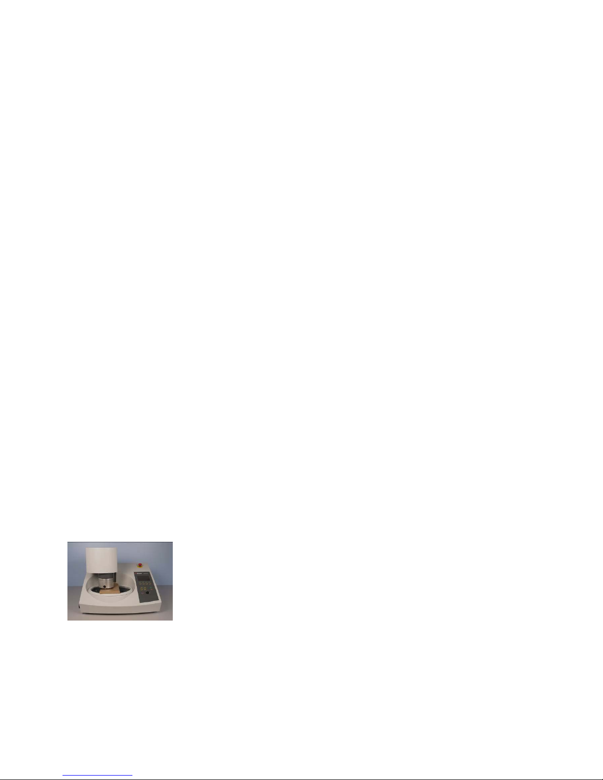
1 Tegramin-25 or Tegramin-30
(Microprocessor controlled table top machine
for automatic grinding, lapping and polishing of all mat erial s)
2 Mains c abl es
1 Water inlet hose 19mm/ ¾" (2 m)
1 Fil ter gas ket
1 Reduction ring with gasket ¾" to ½ "
1 Water outlet hose ø40/ 1½" (1.5 m)
2 Hose c l amps
1 Connection piece (p6 to 1/8")
1 Allen key w. cross handle 6x150 mm
1 Set of Instruction Manuals
Remove the Tegramin from the packing crate:
− Remove the bolts from the right transport bracket that secure
Tegramin to its transport pallet.
− Remove the bracket.
− Holding underneath the base of the machine, from the front
and the back, slide the Tegramin to the right and lift off the
pallet.
Place Tegramin on a steady table with an adequate working
height.
The table must be able to carry at least 91 kg / 200 lb.
Check that the Tegramin is resting securely with all 4 rubber feet
on the table.
The machine must be close to the power supply, water mains
and water outlet facilities.
Slide the piece of cardboard to the right.
Remove the screw holding the transport lock on the cone shaft.
Press the black release button and remove the transport lock.
Checking the Contents
Tegramin-25/ -30
Unpacking Tegramin
Placing Tegramin
Tegramin-25/ -30
Instruction Manual
4
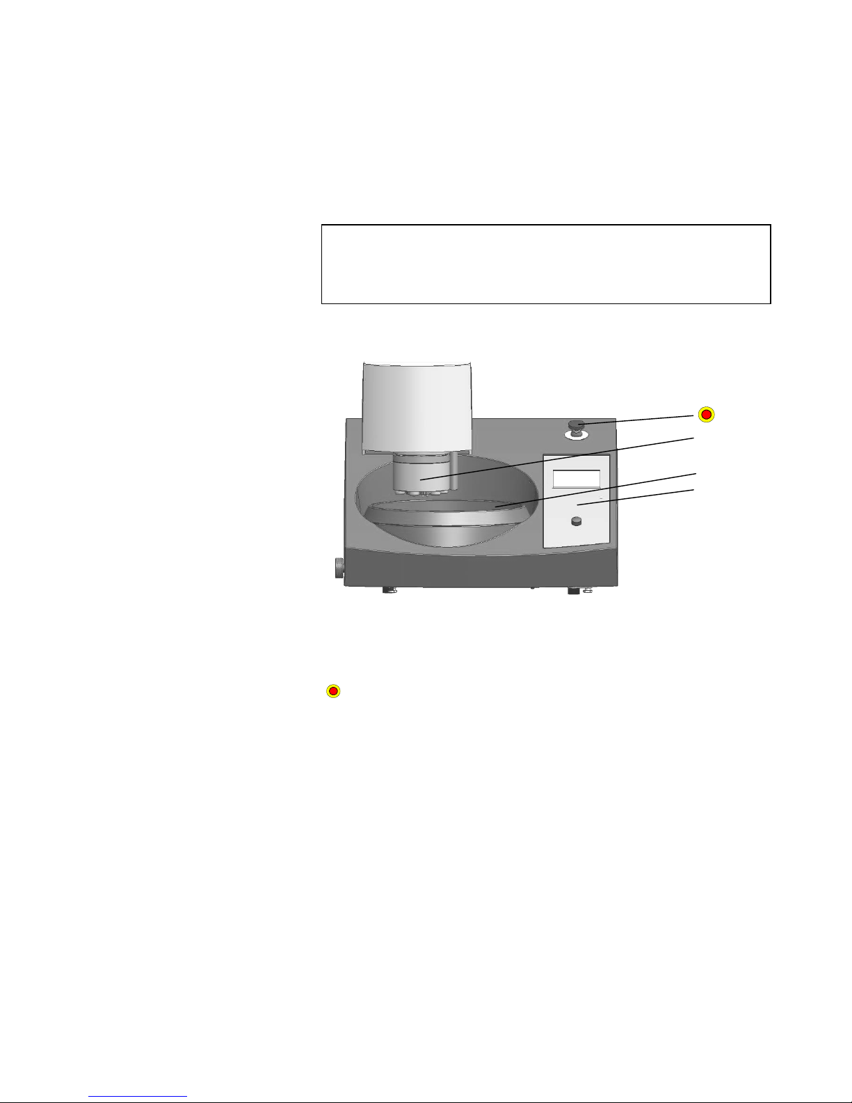
Take a moment to familiarise yourself with the location and names of
all the Tegramin components:
A Dosing block with nozzles
B Turntable
C Front panel control(s)
Emergency Stop
- Push the red button to stop
- Turn the red button clockwise to release
Getting Acquainted with
Tegramin
Please Note,
The following illustrations are of Tegramin versions without a cover.
Installation and operation of Tegramin version s wit h or without a cover
will be identical.
Covers are also available as an optional accessory .
A
B C
Tegramin-25/ -30
Instruction Manual
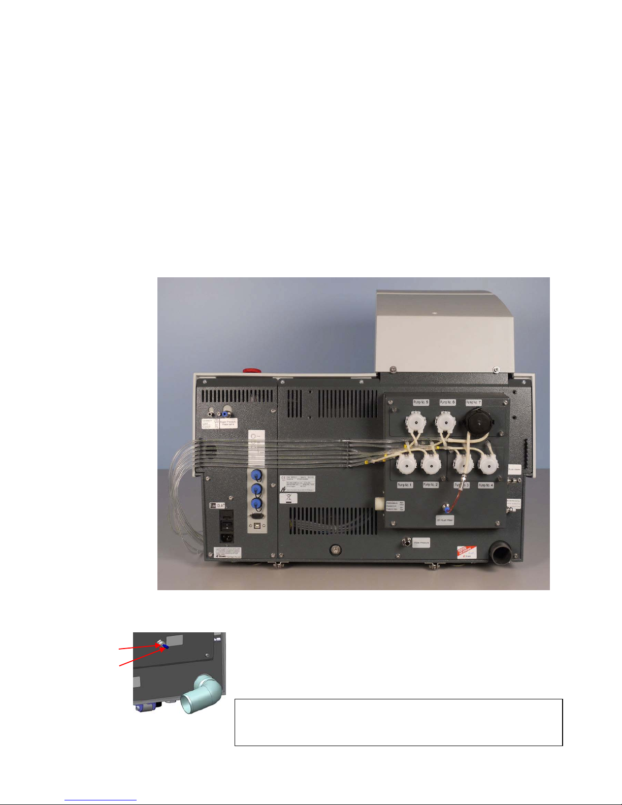
5
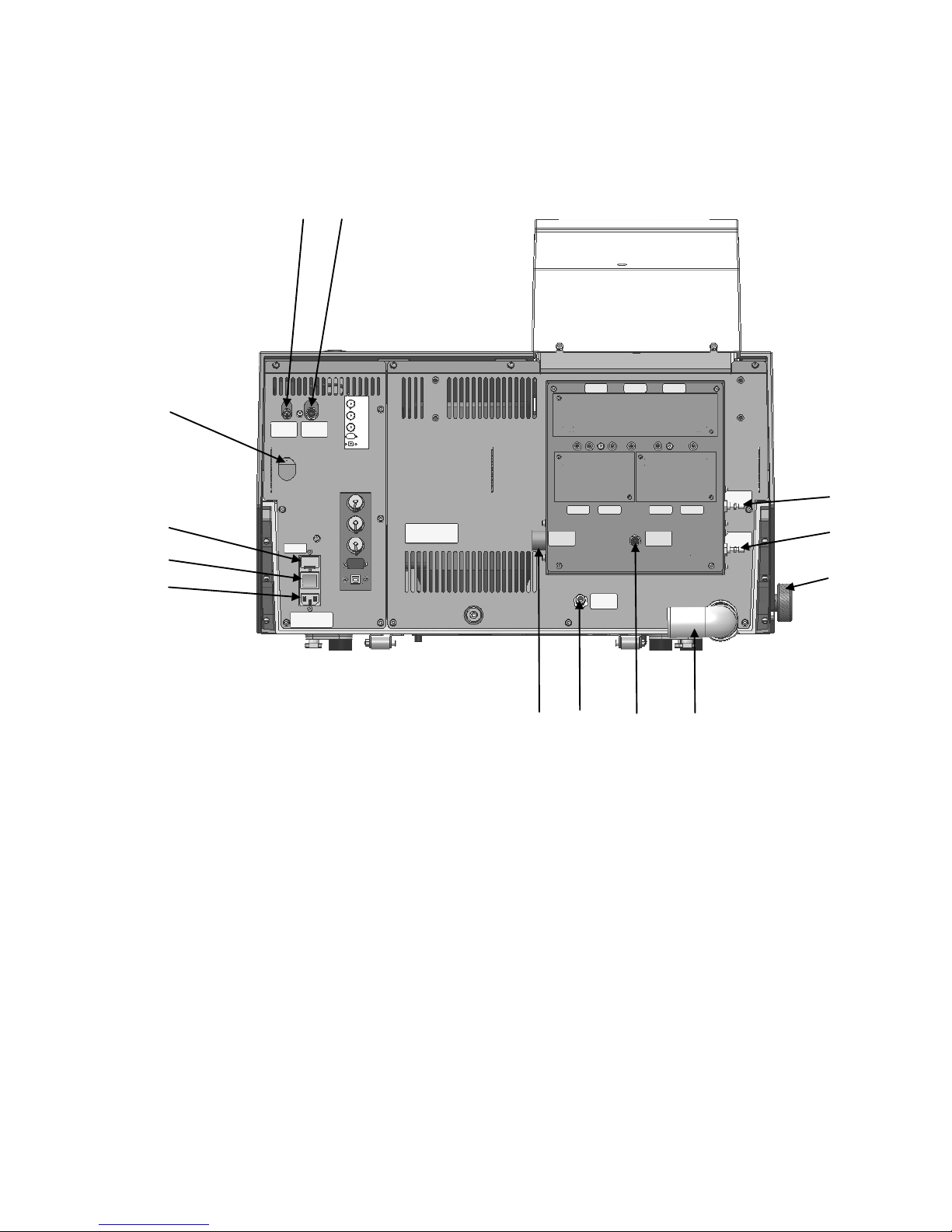
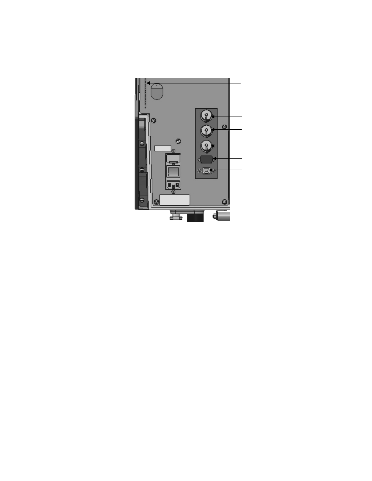
Air outlet for shift valve
Compressed air inlet
Release outlet valve from water/oil filter for compressed air
Fuses
Main switch
Mains connection
Water inlet (mains water ¾")
Water inlet (from Cooling Unit)
OP module, flushing water
Water outlet pipe
Water valve, manual
Throttle valve, disc cooling
Throttle valve, flushing water for OP
Rear of Tegramin
Tegramin-25/ -30
Instruction Manual
6
Holders for dosing tubes
(3 rows on the rear of Tegramin)
Socket for cover
Connection for shift valve)
Cooli unit connection
USB connection, for service purposes
RS 232 socket for LAN module

Tegramin-25/ -30
Instruction Manual
7
Water for wet grinding may be supplied from the water mains or a
Recirculation Cooling Unit (instructions on the next page).
Mount the 90° end of the inlet hose onto the water inlet on the
back of Tegramin (see Getting Acquainted with Tegramin):
− Insert the filter gasket in the coupling nut with the flat side
against the pressure hose.
− Tighten the coupling nut completely.
Mount the straight end of the inlet hose on the water mains tap
for cold water:
− If required, mount the reduction piece with gasket on the
water mains tap and tighten the coupling nut completely.
Mount the outlet hose onto the water outlet pipe. (Lubricate with
grease or soap to facilitate insertion.) Use a hose clamp for
fastening.
Lead the other end of the drain hose to the water outlet. Arrange
the hose so that it slopes downward towards the drain
throughout its length. Shorten the hose, if necessary.
Supplying Water
Connection to Water Mains
IMPORTANT
The cold water supply must have a head pressure in t he
range 1 – 10 bar (14.5 – 145 psi).
Connection to Water Outlet
REMEMBER
Make sure that the drain hose slopes downward towards the drain
throughout its length and avoid sharp bends in the drain hose.
Tegramin-25/ -30
Instruction Manual
8
The flow of water can be adjusted using the manual water valve.
Water flow for disc cooling and flushing after OP can be adjusted
using the throttle valves.
Adjusting the Water Flow
Throttle valve, flushing water for OP
Throttle valve, disc cooling
Manual Water valve
Tegramin-25/ -30
Instruction Manual
9
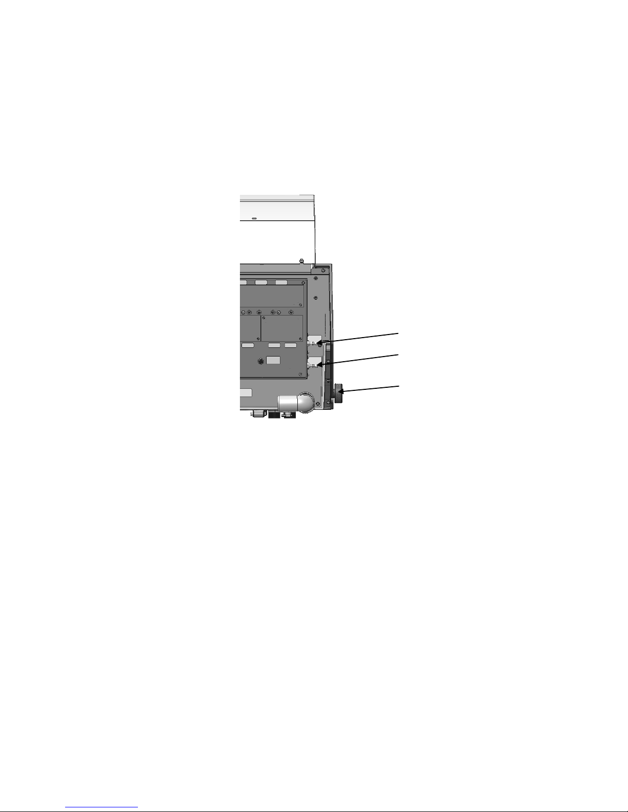
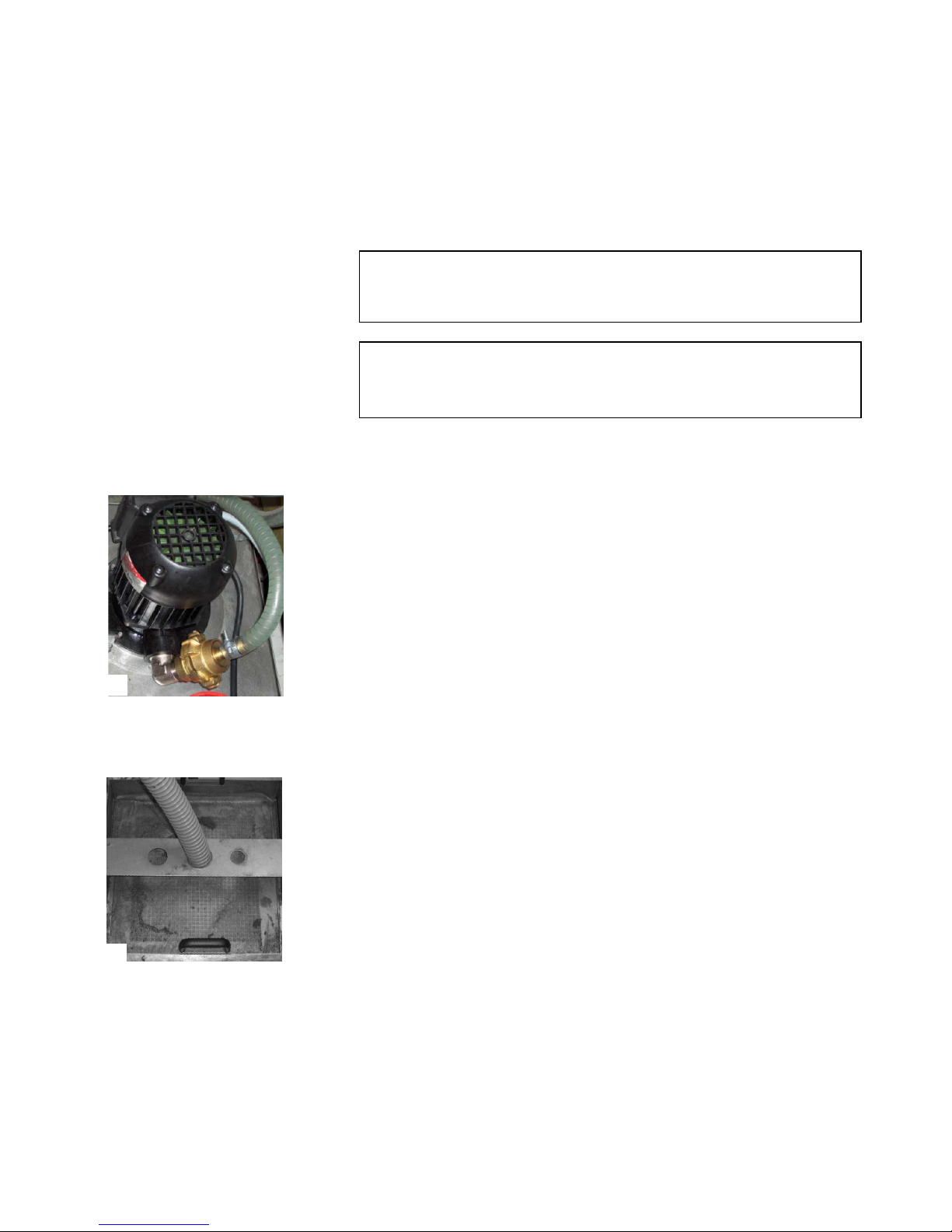
To ensure optimal cooling, Tegramin can be fitted with a Struers
Recirculation Cooling Unit.
Take the hose delivered with the pump and remove the quick
coupling from one end.
Slide the hose clamp onto the hose and connect to the back of the
Tegramin. Tighten the hose clamp.
Connect the quick coupling on the other side of the inlet hose
directly to the cooling unit’s pump outlet (A).
Mount the water outlet hose onto the water outlet pipe. Use a
hose clamp to secure the hose.
Lead the other end into the mounting hole in the bracket on top of
the static filter unit (B).
Arrange the hose so that it slopes downward towards the drain
throughout its length. Shorten the hose, if necessary.
Connecting a Recirculation
Cooling Unit
Oxide Polishing:
A Shift Valve is REQUIRED when using a Recirculation Cooling Unit
with Tegramin units running methods that include the dosing of
oxide polishing suspensions -OP.
Note
Before connecting the cooling unit to the Tegrami n,
follow the instructions in the Struers Cooling Unit s I nstruction Manual
to prepare it for use.
Connecting the Water Inlet
Connecting the Water Outlet
B A

Tegramin-25/ -30
Instruction Manual
10
Connect the communication cable to the Cooli Control Box and
then connect to the socket at the rear of the Tegramin.
With the outlet hose mounted onto Tegramin's water outlet pipe,
mount the other end of the hose onto the pipe labelled From
Tegramin on the shift valve.
Mount a 1.5 m piece of hose onto the pipe marked Cooli and
lead the other end to the recirculation cooling unit. Use a hose
clamp for fastening.
Mount the second 1.5 m piece of hose onto the pipe marked
Drain and lead the other end to the drain. Use a hose clamp for
fastening.
Connect the blue compressed air hose to the air outlet on
Tegramin and fit the other end to the shift valve, marked Connect
to Tegramin.
Connect the plug to the socket at the back of the Tegramin
marked Shift valve.
Connecting the Communication
Cable
IMPORTANT
Before connecting to power, check that the mains voltage corresponds to
the voltage stated on the type plate on the side of t he machine.
Installing the Shift Valve
(Accessory)
IMPORTANT
When connecting Tegramin to both mains water AN D the recirculation
cooling unit you also must install the shift valve for the drain.
Failure to do this may result in emptying or overflowing
the recirculation cooling unit.
Note:
The Shift Valve for Tegramin set includes some extra pieces
not used for Tegramin-25/-30
(1 short piece of hose, 1 reduction piece and 2 hose cl am ps)
REMEMBER
Make sure that the hoses slope downward throug hout their length, from
Tegramin to the shift valve and from shift valv e to Cooli (or drain).
Avoid sharp bends in the hoses. Shorten the hoses, if necessary.
Tegramin-25/ -30
Instruction Manual
11
The quality of the air in the compressed air system used with this
machine must meet the standards stated in ISO 8573-1.
To connect compressed air:
Mount the quick coupling on the compressed air hose and
secure it with the hose clamp supplied.
Connect the air inlet hose to the quick coupling and fit the other
end into the compressed air inlet on Tegramin.
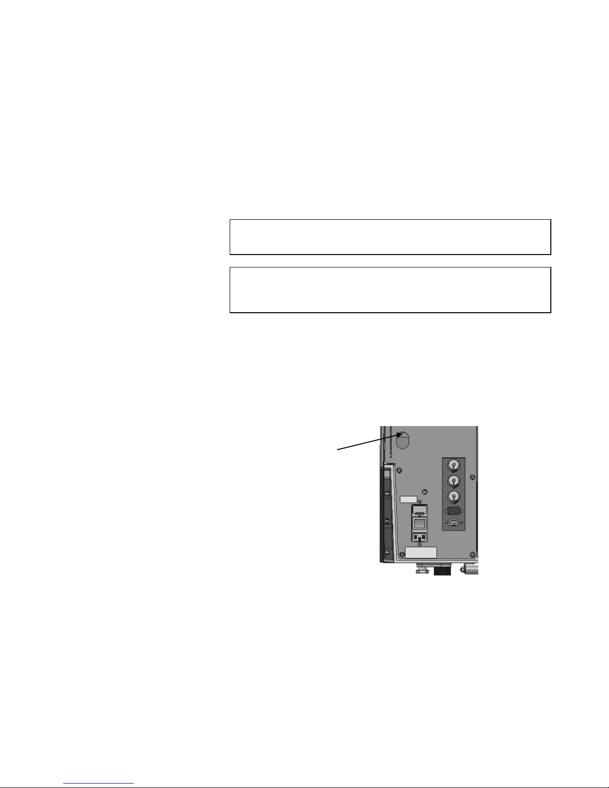
Tegramin is fitted with a water / oil filter that removes excessive
amounts of these substances from the compressed air supply. As a
result of this, it is necessary to empty the filter periodically:
Locate the release outlet valve at the back of the machine.
Hold a cloth under the filter to retain any water released and
press the release valve.
An exhaust system should be connected when using alcohol based
suspensions or lubricants.
Connect a 50 mm pipe to the outlet at the rear of the machine,
on the left and connect to the exhaust system.
Recommended capacity for exhaust system: 180m
3
/h at 0mm water
gauge.
Compressed Air Connections
IMPORTANT
The air pressure must be between 6 bar (87 psi) and 10 bar (145 psi) and
have a quality equal to or better than Class-3, as specified in ISO 8573-1.
Note:
Tegramin requires a continuous flow of compres sed air
through the regulator valve –
a faint hissing sound does not mean that there is an air leak.
Emptying the Water / Oil Filter
Connection to an External
Exhaust System
Tegramin with Cover
(optional/accessory)
Release Outlet Valve
Tegramin-25/ -30
Instruction Manual
12
Always remember to switch the power off when installing electrical
equipment.
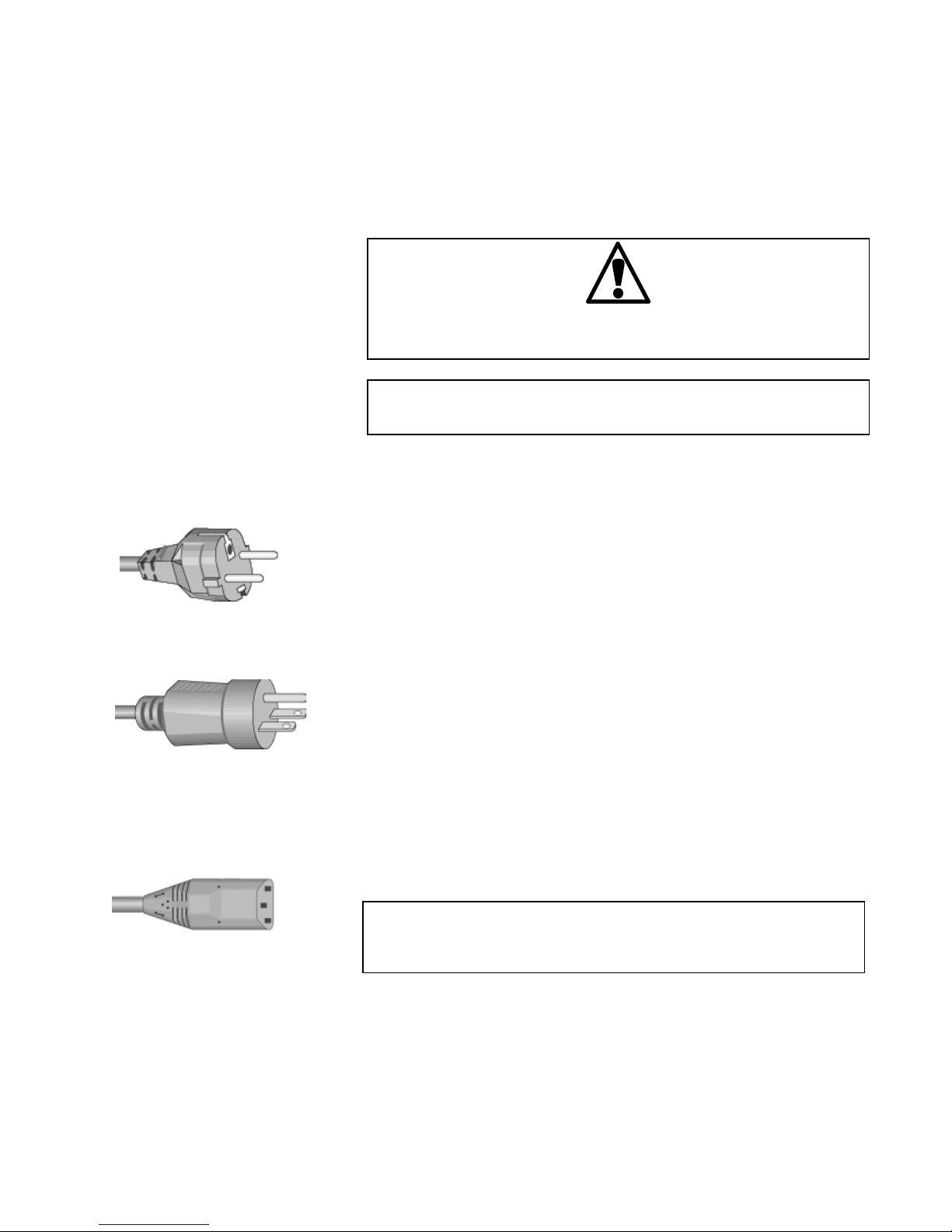
The Tegramin is shipped with 2 types of Mains cables:
The 2-pin (European Schuko) plug is for use on single-phase
connections.
If the plug supplied on this cable is not approved in your country,
then the plug must be replaced with an approved plug. The leads
must be connected as follows:
Yellow/green: earth
Brown: line (live)
Blue: neutral
The 3-pin (North American NEMA) plug is for use on 2-phase power
connections.
If the plug supplied on this cable is not approved in your country,
then the plug must be replaced with an approved plug. The leads
must be connected as follows:
Green: earth (ground)
Black: line (live)
White: line (live)
Both cables are on the other end equipped with an IEC 320 cable
connector that has to be connected to the Tegramin.
Supplying Power
DANGER!
The machine must be earthed
IMPORTANT
Check that the mains voltage corresponds to the v oltage stated
on the type plate on the back of the machine.
Single-phase Supply
2-phase Supply
Connection to the Machine
WARNING!
The output voltage from this cable is 200 – 240V and not 110V.
DO NOT use this cable to connect equipment t hat use a 110V power
supply. Failure to adhere to this may result in material damage.
Tegramin-25/ -30
Instruction Manual
13
Remove the cover plates.
Slide the dosing module(s) into the correct position at the back of
Tegramin.
Secure the module(s) with the attached screws.
Connect the short piece of tube with the 90° angle and the clear
tube to the connectors at the back of the Tegramin.
Lead the long tubes from the pumps to the bottles of
lubricant/abrasive and connect them to the nipple on top of the
bottles.
The tubes can be pressed into place in the dosing tube holders
on the rear of Tegramin.
When mounting a module with an OP pump:
Push the connector disc inwards and remove the blue plug from
the OP Flush water connector.
Lead the tube from the OP pump (Pump No. 7 in the picture),
press the connector disc inwards and insert the tube into the
connector.
Mounting the Dosing Modules
OP dosing
NOTE!
The tubes from the 2 DP-dosing modules are numbered 1/3 or 2/4.
Depending on the position the dosing modules are placed in please remove
the numbers that do not match, on both ends of the t ube.
Connector Disc
Plug
Tegramin-25/ -30
Instruction Manual
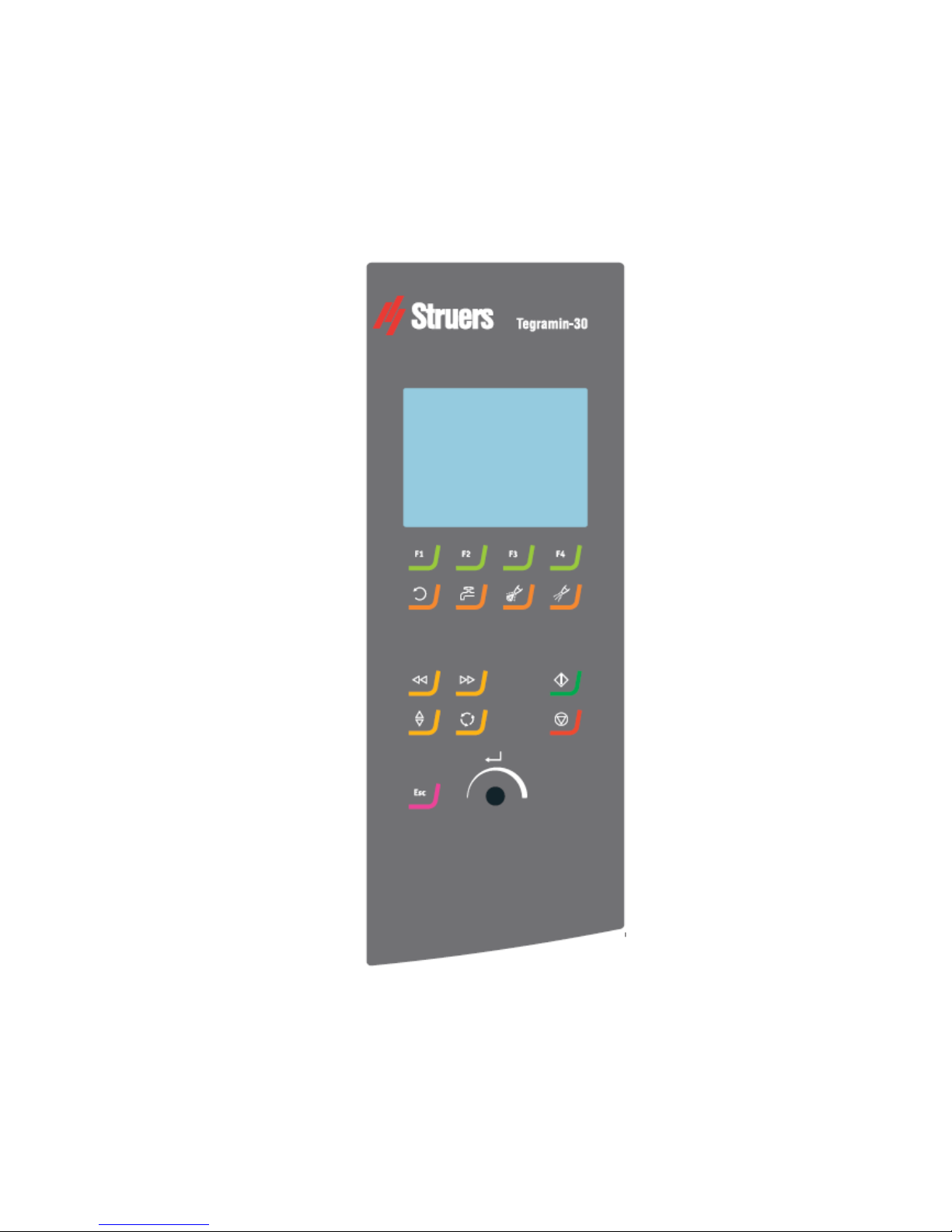
14
2. Basic Operation of Tegramin
Front Panel
Tegramin-25/ -30
Instruction Manual
15
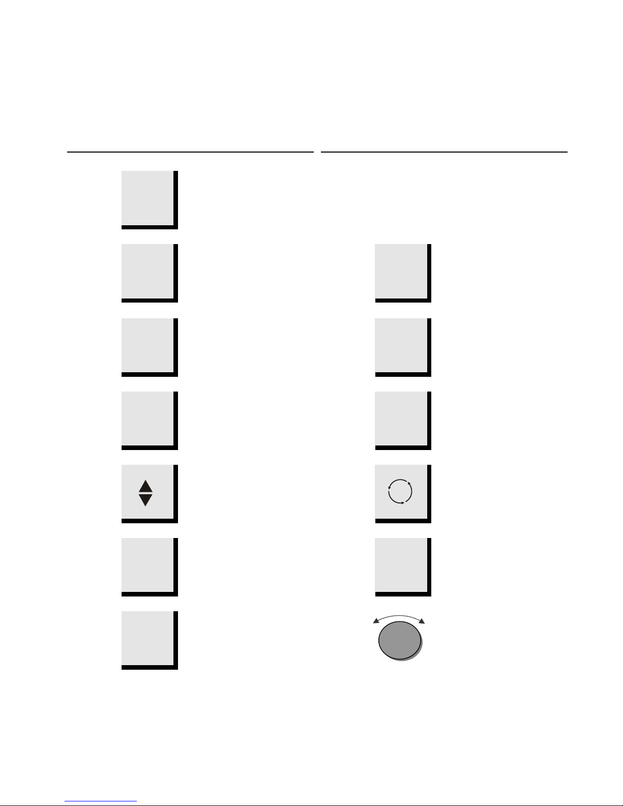
Key Function
Key Function
FUNCTION
KEY
F1-F4
Controls for various purposes.
See the bottom line of the
individual screens.
DISC
ROTATION
Starts rotation of the disc.
WATER
Manual override - push button to
apply water (applies water when
no process is running).
Push button again to stop
applying water (water will
automatically switch off after 5
min.)
LUBRICANT
Only active when dosing units
are installed.
Manual override – push button to
apply lubricant from the doser
bottle.
ABRASIVE
Only active when dosing units
are installed.
Manual override – push button to
apply diamond suspension from
the doser bottle.
LEFT
Moves the specimen holder
head left.
RIGHT
Moves the specimen holder
head right.
LOWER/
RAISE
Lowers & raises the specimen
mover head when preparing
single specimens or when
adjusting positions of specimen
mover plate or specimen holder.
ROTATE
Rotates the Specimen Mover
Plate.
START
Starts the preparation process.
STOP
Stops the preparation process.
ESC
Esc
Returns to the Main Menu or
aborts functions/changes.
Turn/Push
Knob
Used for entering and changing
steps and parameters.
Combined cursor and enter key.
Enables selected parameter
values to be activated for editing.
Saves the edited parameter
values.
Toggles when only 2 options
available.
Front Panel Controls
↵
 Loading...