


LaboPress-3
Instruction Manual
Manual No.: 15087003
Date of Release 11.01.2008


LaboPress-3
Instruction Manual
Table of Contents Page
User’s Guide ..............................................................1
Reference Guide.......................................................13
Quick Reference Card .............................................24
Always state Serial No and Voltage/frequency if you have technical questions or when ordering spare parts.
You will find the Serial No. and Voltage on the type plate of the machine itself. We may also need the Date
and Article No of the manual. This information is found on the front cover.
The following restrictions should be observed, as violation of the restrictions may cause cancellation of
Struers legal obligations:
Instruction Manuals: Struers Instruction Manual may only be used in connection with Struers equipment
covered by the Instruction Manual.
Service Manuals: Struers Service Manual may only be used by a trained technician authorised by Struers.
The Service Manual may only be used in connection with Struers equipment covered by the Service Manual.
Struers assumes no responsibility for errors in the manual text/illustrations. The information in this manual is
subject to changes without notice. The manual may mention accessories or parts not included in the present
version of the equipment.
The contents of this manual is the property of Struers. Reproduction of any part of this manual without the
written permission of Struers is not allowed.
All rights reserved. © Struers 2008.
Struers A/S
Pederstrupvej 84
DK-2750 Ballerup
Denmark
Telephone +45 44 600 800
Fax +45 44 600 801


LaboPress-3
Instruction Manual
LaboPress-3
Safety Precaution Sheet
To be read carefully
before use
1. The operator should be fully aware of the use of the machine according
to the Instruction Manual.
2. The machine must be placed in a well ventilated room on a working
table with adequate height for convenient operation.
3. Be sure that the actual voltage corresponds to the voltage stated on the
back of the machine and on the heating/cooling unit. The machine must
be earthed.
4. Be sure that the water connections are mounted correctly and without
leaks. The main water supply should be turned on when the machine is
in use.
Struers recommend that the mains water supply is shut off or
disconnected if the machine is to be left unattended
5. Be sure that the outlet hose is safely attached to the water outlet
system.
6. Be sure that the mounting unit is correctly assembled on the press
before starting the process.
7. Be sure that the top closure with upper ram is either correctly mounted
on the mounting cylinder or completely removed from the mounting
cylinder before starting the press.
8. Do not operate the mounting press with a higher force/pressure than
recommended for the actual cylinder diameter and resin in Struers
Application Guide for Hot Mounting.
9. Following a heating cycle, ensure the mounting cylinder is cooled for a
minimum of two minutes before opening.
10. Do not operate the machine whilst assembling or disassembling the
mounting unit.
The equipment is designed for use with consumables supplied by Struers. If subjected to misuse, improper
installation, alteration, neglect, accident or improper repair, Struers will accept no responsibility for
damage(s) to the user or the equipment.
Dismantling of any part of the equipment, during service or repair, should always be performed by a qualified
technician (electromechanical, electronic, mechanical, pneumatic, etc.).


LaboPress-3
Instruction Manual
User’s Guide
Table of Contents Page
1. Getting Started
Checking the Contents ..................................................................... 2
LaboPress-3................................................................................ 2
Mounting Unit ........................................................................... 2
Unpacking LaboPress-3.................................................................... 2
Placing LaboPress-3 .........................................................................2
Transport Screw Cap........................................................................ 2
Getting Acquainted with LaboPress-3............................................. 3
Noise Level........................................................................................ 4
Supplying Power...............................................................................4
Supplying Water ............................................................................... 4
Water Inlet................................................................................. 4
Water Outlet..............................................................................4
Assembling the Mounting Unit........................................................ 5
Removing the Cover ..................................................................5
Installing the Lower Ram ......................................................... 5
Installing the Mounting Unit.................................................... 5
Installing the Cover................................................................... 6
Installing the Dust Protection Ring .........................................6
Disassembling the Mounting Unit................................................... 6
Dropping the Lower Ram.......................................................... 6
Removing the Dust Protection Ring ......................................... 6
Removing the Cover ..................................................................6
Removing the Mounting Unit ..........................................................7
Removing the Lower Ram ................................................................ 7
Changing the Mounting Unit........................................................... 7
2. Basic Operations
Using the Controls............................................................................ 8
Front Panel Controls of LaboPress-3 .......................................8
Acoustic Signals......................................................................... 8
Main Switch............................................................................... 8
Placing the Specimen .....................................................................10
Pouring Resin over the Specimen........................................... 10
Placing Two Specimens .................................................................. 10
Installing the Top Closure.............................................................. 11
Starting the Mounting Process ...................................................... 12
Preheating with Low Pressure ...............................................12
Stopping the Mounting Process ..................................................... 12
Removing the Top Closure ............................................................. 12
1

Checking the Contents
LaboPress-3
Instruction Manual
1. Getting Started
In the packing box you should find the following parts:
LaboPress-3
Mounting Unit
Unpacking LaboPress-3
Placing LaboPress-3
Transport Screw Cap
1 LaboPress-3 machine
1 Pressure hose
1 Filter gasket
1 Gasket
1 Reduction ring with gasket
2 Measuring spoons for mounting resin
1 Funnel
1 Air filter
1 Set of Instruction manuals
1 Mounting unit
1 Top closure with upper ram
1 Lower ram
1 Dust protection ring
1 Piston pin
1 Mould release agent (FASTI)
1 Scraper (PROAN)
LaboPress-3 is detached from the bottom of the packing case by
removing the four screws from below.
LaboPress-3 should be placed on a steady table with an adequate
working height. The machine must be placed close to the power
supply, water mains and water outlet facilities. If water
recirculation is used, there must be room under the table for the
Recirculation Cooling Unit (TRECI).
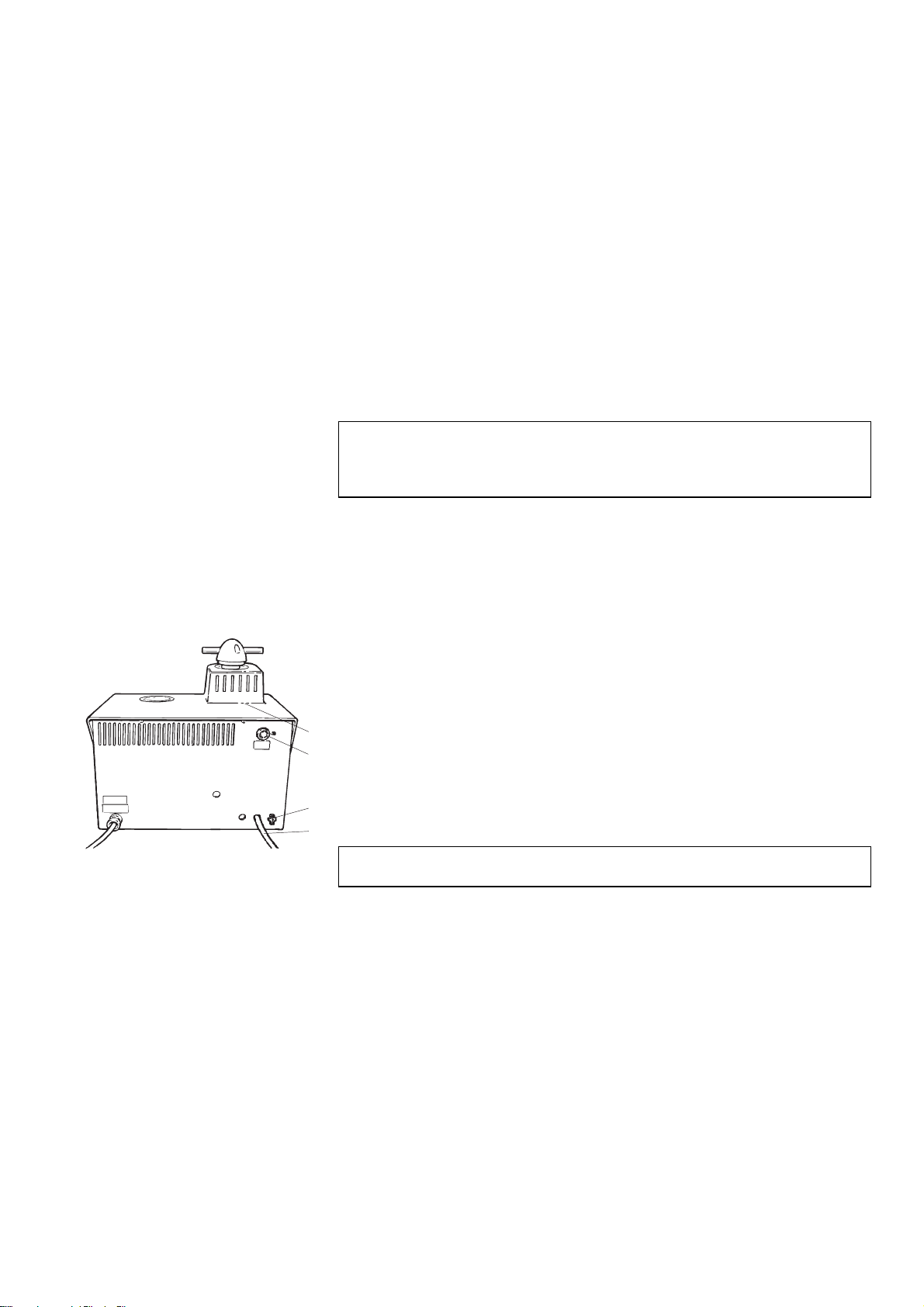
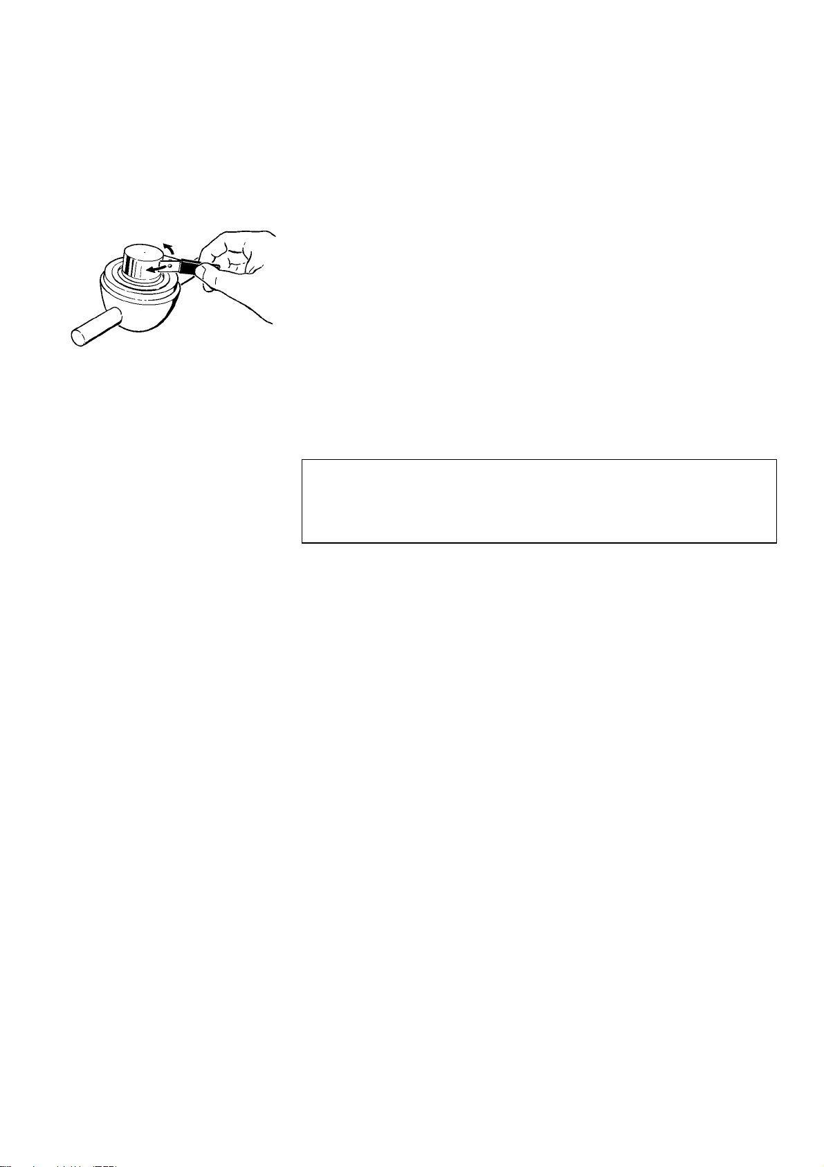
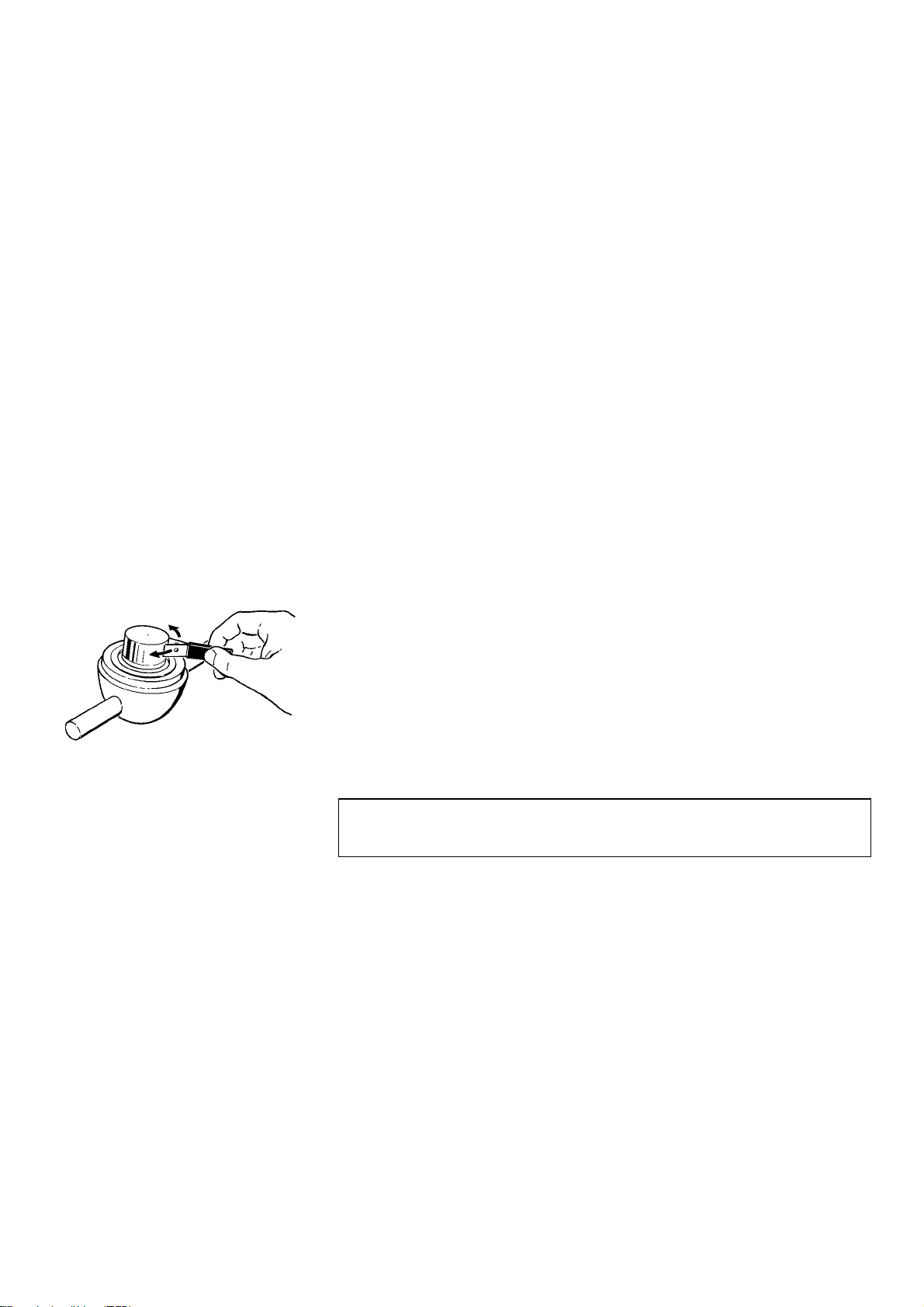
Carry out the following procedure before using the machine for
the first time. Exchange the transport screw cap with the
enclosed air filter , to equalise the pressure in the hydraulic
system.
The transport screw cap is situated
underneath the cover for the mounting unit.
2

LaboPress-3
Instruction Manual
Getting Acquainted with
LaboPress-3
Take a moment to familiarise yourself with the location and
names of the LaboPress-3 components.
➁
➄
➃
➅
➀
➆
➂
Front panel
Top closure
Main switch
Mounting unit
Dust protection ring
Cover for mounting unit
Top closure holder
3
LaboPress-3
Instruction Manual
Noise Level
Supplying Power
Supplying Water
Water Inlet
Water inlet
Water outlet tube
Water Outlet
The noise level of the machine is 60 dB (A) measured when the
pump is running, at a distance of 1.0 m/39.4” from the machine.
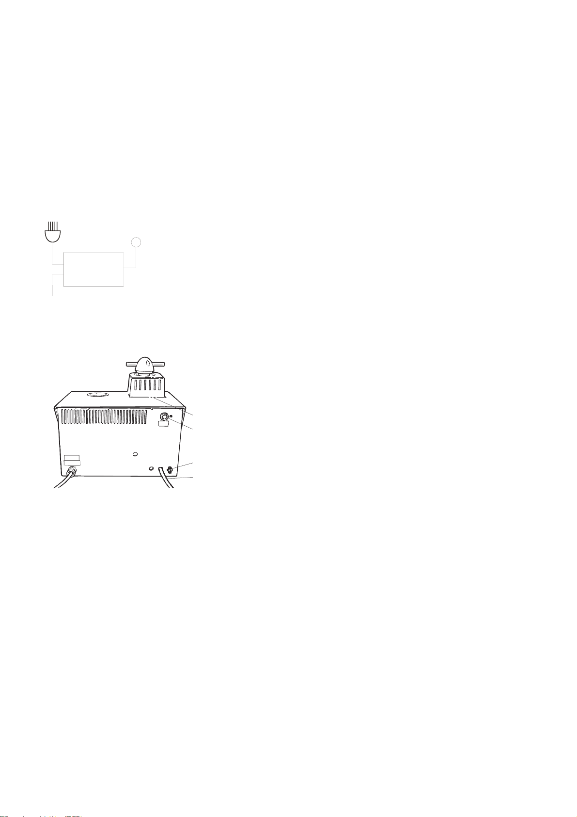
LaboPress-3 is factory mounted with an electric cable. Mount a
plug on the cable:
Brown: phase
Blue: neutral
Yellow/green: earth
IMPORTANT
Check that the mains voltage corresponds to the voltage stated on the type
plate on the machine. Do not operate the machine before the transit screw
cap has been exchanged with the enclosed air filter.
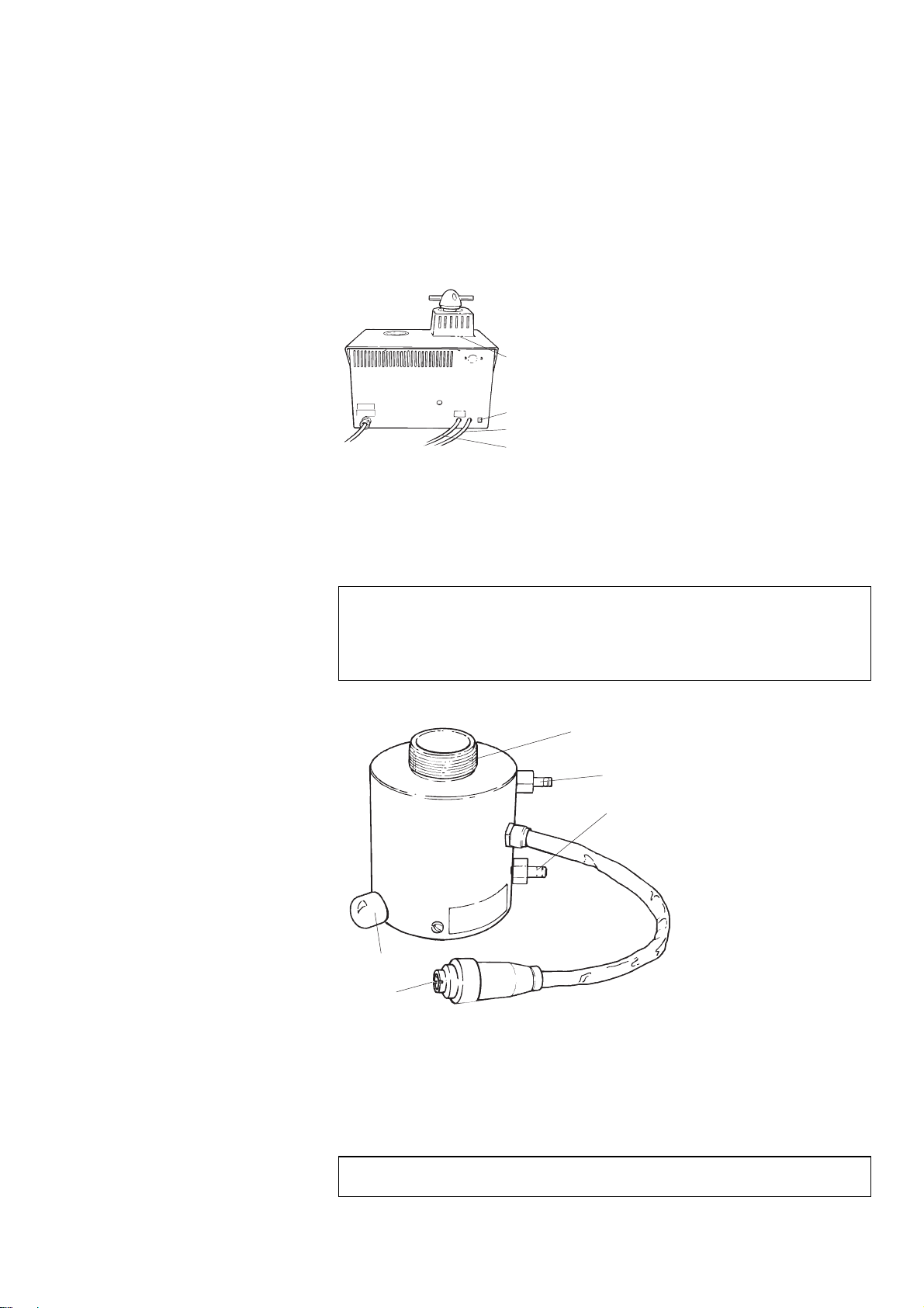
Water for cooling may be supplied from the water mains or a
Recirculation Cooling Unit.
Mount the pressure hose onto the water inlet tube (pos.1) on the
back of the machine:
Insert the filter gasket in the coupling nut with the flat side
against the pressure hose.
Tighten the coupling nut completely.
➃
Mount the other end of the pressure hose on the water mains tap
for cold water:
➀
Mount the reduction ring with gasket on the water mains tap,
➄
➁
if necessary.
Introduce the gasket and tighten the coupling nut completely.
IMPORTANT
Only connect to cold water
Lead the water outlet tube (pos. 2) to the drain and be
absolutely sure to place the hose with a steady downward
slope and without any obstructions.
Attach the water outlet tube to the water outlet system.
4
LaboPress-3
Instruction Manual
Assembling the Mounting Unit
Removing the Cover
Installing the Lower Ram
Installing the Mounting Unit
Press the catch (pos. 4).
Press gently on both sides of the cover to release it, and lift it
up.
➃
➄
➁
➀
Catch
Place the lower ram on the top of the piston rod.
Turn the lower ram so that the holes in the axle journal on
top of the rod and ram line up, and insert the piston pin.
Make sure that the ends of the pin do not protrude.
IMPORTANT
The axle journal is part of the machine’s safety mechanism to protect
against damage to the machine. Please see: Maintenance. If it breaks, it
must only be replaced with a Struers replacement part or the safety
mechanism may not function.
➀
➂
➃
➁
➄
Mounting cylinder
Fixation screw
Upper quick coupling for cooling water
Lower quick coupling for cooling water
Plug
IMPORTANT
Do not operate the machine whilst installing the mounting unit
5
Installing the Cover
➃
➄
➁
➀
Catch
Installing the
Dust Protection Ring
Disassembling
the Mounting Unit
Dropping the Lower Ram
Removing the
Dust Protection Ring
Removing the Cover
LaboPress-3
Instruction Manual
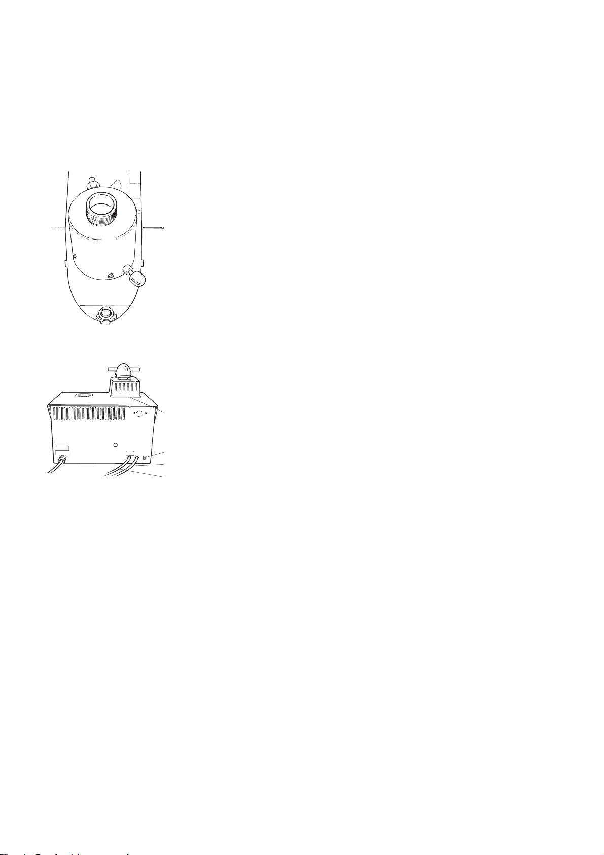
Unscrew the fixation screw about 10 mm.
Place the mounting cylinder over the lower ram with the
fixation screw in the position shown.
Turn the mounting unit in a clockwise direction until it stops.
Tighten the fixation screw completely.
Mount the tube with the straight quick coupling on the lower
quick coupling (position 4) of the mounting unit and push to
connect. Make sure that the ring comes to stop in the extreme
end of the quick coupling.
Mount the tube with the elbow quick coupling on the upper
quick coupling of the mounting unit (pos. 3) and push to
connect. Make sure that the ring comes to stop in the extreme
end of the quick coupling.
Mount the plug (pos. 5) in the socket. Tighten the coupling
nut.
Insert the barb into the front of the opening for the cover.
Insert the barbs on both sides of the cover into the cabinet.
Press the sides of the cabinet gently.
Press the rear end of the cover in so that the catch engages.
Place the dust protection ring around the mounting cylinder. The
concave side should face upwards.
Switch on the main power of the machine.
Press the key RAM DOWN
N to lower the ram to its lower
limit.
Lift out the dust protection ring.
Press the catch (position 4 above).
Press gently on both sides of the cover, to release it, and lift it
up.
6

LaboPress-3
Instruction Manual
Removing the Mounting Unit
➀
➂
➃
➁
➄
Removing the Lower Ram
Changing the Mounting Unit
IMPORTANT
Do not operate the machine whilst removing the mounting unit
Mounting cylinder
Fixation screw
Upper quick coupling for cooling water
Lower quick coupling for cooling water
Plug
Disconnect the plug (pos. 5) in the socket. Loosen the coupling
nut and pull.
Disconnect the tube with elbow quick coupling on the upper
quick coupling on the mounting unit (pos. 3). Pull the ring.
Wait 5 seconds to allow the water to flow out of the cooling
coil.
Disconnect the tube with straight quick coupling on the lower
quick coupling on the mounting unit (pos. 4). Pull the ring.
Unscrew the fixation screw about 10 mm.
Turn the mounting unit in an anti-clockwise direction until it
stops.
Lift the mounting unit.
Push the piston pin out of the lower ram and lift it off.
IMPORTANT
The axle journal is part of the machine’s safety mechanism to protect
against damage to the machine. Please see: Maintenance. If it breaks, it
must only be replaced with a Struers replacement part or the safety
mechanism may not function.
Follow the instructions for Removing the Mounting Unit and
Installing the Mounting Unit.
7
Using the Controls
A
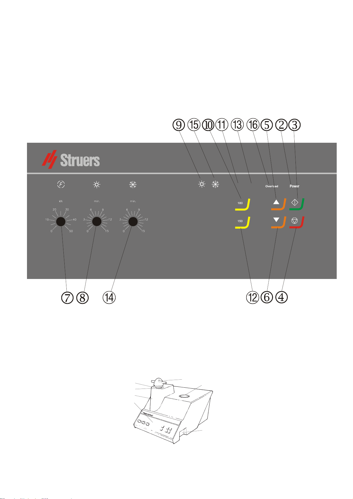
Front Panel Controls of
LaboPress-3
LaboPress-3
Instruction Manual
2. Basic Operations
180°C
LaboPress-3
150°C
coustic Signals
Main Switch
8
Short Beep: when a key is pressed, a short beep indicates
that the command has been accepted.
Long Beep: a long beep indicates that the key is inactive at
that moment.
Three long beeps: indicate that the mounting process is
finished.
➄
➃
➅
➀
➁
➆
c Front panel
e Main switch
➂

LaboPress-3
Instruction Manual
Pos. No. Key/Knob Function Pos. No. Key/Knob Function
MAIN
SWITCH
Turns the main power of the machine
on/off. The main switch is located to
the right of the cabinet.
HEATING
INDICATOR
¹
Lights up when heating is on.
POWER
POWER
START
s
STOP
o
RAM
UP
O
RAM
DOWN
N
Lights up when the main power is on.
Starts the automatic mounting
process.
Stops the mounting process,
followed by automatic release of
pressure. Stops the movement of the
lower ram.
Starts the upward movement of
lower ram. When started: stops the
upward movement of the lower ram.
The ram automatically stops when
the upper limit is reached.
Starts the downward movement of
lower ram. When started: Stops the
downward movement of the lower
ram. The ram automatically stops
when the lower limit is reached.
HEATING
1
HEATING
INDICATOR
2
HEATING
3
HEATING
INDICATOR
4
COOLING
180°C
180°C
150°C
150°C
¸
Selects a heating temperature of
180°C.
Lights up when the heating
temperature is set to 180°C.
Selects a heating temperature of
150°C.
Lights up when the heating
temperature is set to 150°C.
Adjustable knob for setting the
cooling time.
FORCE
f
HEAT
¹
Adjustable knob for setting the force
(pressure).
Adjustable knob for setting the
heating time.
5
COOLING
INDICATOR
6
OVERLOAD
¸
OVERLOAD
Lights up when cooling is on.
Lights up if the motor has been
overloaded.
9

LaboPress-3
Instruction Manual
Placing the Specimen
Pouring Resin over the Specimen
Placing Two Specimens
Press and hold RAM UP
limit.
Apply “Mould Release Agent” to the surface of the lower ram.
Place the specimen on the ram. The specimen must be clean,
dry and free from grease. The distance between the specimen
and the cylinder wall must be minimum 3 mm to avoid cracks
in the resin.
Press and hold RAM DOWN
limit.
Fill a suitable amount of resin into the cylinder by means of
the enclosed funnel.
Always make sure there is sufficient resin to cover the sample
after compression. Please note that the volume of the resin
reduces when the granulate becomes compressed. If insufficient
resin is used, the rams may come in contact with the sample, and
the cylinder may be damaged.
The “Mould Release Agent” must always be applied to the mounting rams
as a thin layer to prevent the resins sticking to the surface. By means of
Struers AntiStick a thin layer of stearate powder can easily be dabbed on
Follow the instructions in Placing the Specimen.
Apply “Mould Release Agent” to all surfaces of the
intermediate ram.
Place the intermediate ram on top of the resin.
Place the second specimen on the intermediate ram and fill
the cylinder with an adequate quantity of resin.
Again, make sure you use adequate resin!
O to raise the lower ram to its upper
N to lower the ram to its lower
Important
the rams.
10
LaboPress-3
Instruction Manual
Installing the Top Closure
Remove resin dust from the upper part of the mounting
cylinder.
Clean the cylindrical surface of the upper ram. Cured resin
can easily be removed without damage to the surface of the
ram using the scraper supplied.
Apply “Mould Release Agent” to all accessible surfaces of the
upper ram.
Place the top closure with the upper ram on the mounting
cylinder.
Press the top closure straight down, turning it counter-
clockwise until you hear a click.
Press the top closure down and turn it clockwise until its
lower limit.
Turn the top closure a quarter of a turn back.
Important
If the ram does not fit in the cylinder then check ram and cylinder for cured
resin. The tolerance between the cylinder and the ram is very fine and even
small amounts of resin from previous mounting may cause problems.
11

LaboPress-3
Instruction Manual
Starting the Mounting Process
Preheating with Low Pressure
Stopping the Mounting Process
Removing the Top Closure
Set the force.
Set the heating time.
Set the heating temperature (180/150°C).
Set the cooling time.
Press START
The mounting process can be followed on the heating and
cooling indicators.
Set the force to a low value to begin with. Adjust the force after
the desired period of preheating.
The machine automatically stops and relieves the pressure
when the cooling time has elapsed. The machine can be
stopped at any time during the mounting process by pressing
STOP
Cool the mounting cylinder in minimum 2 min before opening, after a
heating period. Please note that the mount possibly will be destroyed.
When the mounting process is finished:
Turn the top closure counter-clockwise until released from the
threads.
Press RAM UP
Place the top closure in the top closure holder.
o.
If you have stopped the machine during the mounting process:
s, and the process will run automatically.
O to raise the lower ram to its upper limit.
12

LaboPress-3
Instruction Manual
Reference Guide
Table of Contents Page
1. Advanced Operations
Installation of Recirculation Cooling Unit (Optional) ..................14
Socket for Recirculation ..........................................................14
2. Struers Metalog Guide™
............................................... 15
3. Application Guide for Hot Mounting
........................ 15
4. Accessories
......................................................................... 16
5. Consumables
....................................................................... 17
6. Trouble-Shooting
............................................................... 18
7. Maintenance
Daily Service ................................................................................... 20
Monthly Service .............................................................................. 20
Cleaning under the Lower Ram.............................................. 20
Cleaning the Rams .........................................................................20
Removing the Upper Ram .............................................................. 21
Lubricating the Threads for the Top Closure................................ 21
Decalcifying the Cooling Coil in the Mounting Unit..................... 21
Replacing the Cooling Water.......................................................... 22
Checking the Recirculating Cooling Unit...................................... 22
8. Technical Data
................................................................... 23
13
Installation of Recirculation
Cooling Unit (Optional)
LaboPress-3
Instruction Manual
1. Advanced Operations
A Recirculation Cooling Unit (TRECI) can be connected by means
of a Recirculation Cooling Unit Connector (ROPRE).
TRECI
ROPRE
LaboPress-3/
ProntoPress-10/ProntoPress-20
Socket for Recirculation
Outlet hose
Socket for recirculation
Connect the cable from the pump in TRECI to ROPRE, according
to the diagram of ROPRE.
Connect the cable with plug from ROPRE to the socket
(pos. 5) on the back of the mounting press.
Connect the cable from ROPRE to the mains.
Check that the pump rotates in the direction indicated on the
pump. If the direction is incorrect, switch two of the phases in
the connection to the pump in TRECI (3-phase versions only).
Replace the outlet tube on the pump in TRECI with the non-
➃
➀
➄
➁
return valve with elbow and hexagon nipple from ROPRE.
Struers recommends that you seal the threads.
Connect the pressure hose of the mounting press to the
hexagon nipple. Remember to mount the gasket.
Lead the outlet hose (pos. 2) to the inlet on TRECI. Be
absolutely sure to place the hose with a steady downward
slope and without obstructions.
Attach the water outlet to the inlet of TRECI.
14

LaboPress-3
Instruction Manual
2. Struers Metalog Guide™
Struers Metalog Guide
common materials, based on a simple analysis of two key properties: hardness and ductility. Finding the right method, including
choice of consumables is easy. Always consult Struers Metalog
Guide
mens.
for the correct preparation method for the actual speci-
offers preparation methods for the most
Metalogram
Metalog Method:
Preparation Philosophy
Metalog Process
Metalog Master
Metalog Code
Struers Metalog Guide
A quick and safe guide to the right preparation method.
A complete catalogue of preparation methods, based on Struers’
extensive materialographic experience, and employing Struers’
range of consumables.
The basics of modern specimen preparation, seen from a
professional point of view.
The materialographic preparation process from start to finish,
logically explained.
A combined trouble-shooting guide and supply of in-depth
information on the processes of mechanical preparation, including
an expert system for the solving of preparation problems.
Quick access to the relevant consumables for the chosen
preparation methods.
contains 6 useful chapters:
Struers Metalog Guide
A complete guide to materialographic specimen preparation. Contact your
local dealer for a free copy of Metalog Guide.
3. Application Guide for Hot Mounting
Useful mounting data and hints can be found in the Struers
Application Guide for Hot Mounting or visit the Struers website
on http://www.struers.com
and see the section on Knowledge
15

LaboPress-3
Instruction Manual
4. Accessories
Type Description Code
Mounting Unit
consisting of cylinder, upper and lower ram, heating/cooling
unit and top closure
Intermediate Ram
for making 2 simultaneous mounts
Recirculation Cooling Unit
Recirculation Cooling Unit Connector
for connection of Recirculation Cooling Unit (TRECI) to
LaboPress-3.
25 mm dia.
30 mm dia.
1 ¼” dia.
1 ½” dia.
40 mm dia.
50 mm dia.
25 mm dia.
30 mm dia.
1 ¼” dia.
1 ½” dia.
40 mm dia.
50 mm dia.
TRECI
ROPRE
CYNMI
CYNTE
CYNQU
CYNHA
CYNIF
CYNAM
CYLDO
CYLDO
CYLDO
CYLDO
CYLDO
CYLDO
16

LaboPress-3
Instruction Manual
5. Consumables
Resin Application Specific property Material Contents Code
ConduFast
(Resin 1)
SpeciFast
(Resin 3)
PolyFast Edge retention Very low shrinkage
Examination in scanning
IsoFast
(Resin 4)
DuroFast
(Resin 5)
MultiFast Routine examination,
MultiFast
Green
MultiFast
Brown
Product Application Specific property Material Contents Code
Pre-Mount
Product Application Material Contents Code
Mount
Release Wax
AntiStick
Electropolishing Electrically conductive
Glass clear mounts
Porous samples
Surface electrical insulator
for ConduFast
electron microscope
Edge retention
Planeness
Edge retention
Planeness
Backup resin
Routine examination
Colour marking
Routine examination
Colour marking
Very low shrinkage
Transparent
Medium shrinkage
Medium removal rate
Electrically conductive
Low emission in the
vacuum chamber.
Low shrinkage
Low removal rate
Very low shrinkage
Good adhesion
Very low removal rate
Low shrinkage
Medium removal rate
Low shrinkage
Medium removal rate
Low shrinkage
Medium removal rate
Serial mounting of
uncomplicated shapes
Easy to handle
Low shrinkage
Medium removal rate
To avoid sticking of the
mounts to the rams
To avoid sticking of the
mounts to the rams
Wax 24 g PREWA
Very fine stearate powder 8 g FASTI
Acrylic resin with iron
powder filler
Thermoplastic, Grey
Acrylic
Thermoplastic
Phenolic resin with carbon
filler
Thermosetting, Black
Dialylphtalate with glass
fibre filler
Thermosetting, Green
Epoxy with mineral filler
Thermosetting, Black
Phenolic resin with wood
flour filler
Thermosetting, Black
Phenolic resin with wood
flour filler
Thermosetting, Green
Phenolic resin with wood
flour filler
Thermosetting, Brown
Phenolic resin with wood
flour filler
In tablet form
Thermosetting, Black
1 kg RESFE
1.5 kg
7.5 kg
25 kg
1 kg
7.5 kg
1 kg
7.5 kg
1 kg
7.5 kg
2.5 kg
7.5 kg
25 kg
2.5 kg
7.5 kg
25 kg
2.5 kg
7.5 kg
25 kg
25 mm/
1” dia.
approx.
1100 pcs.
10 kg
30 mm/
1.1/4” dia.
approx.
760 pcs.
10 kg
40 mm/
1 ½” dia.
approx.
460 pcs.
10 kg
RESTH
RESYV
RESFA
FAPSA
FAPME
RESDI
RESTY
RESIF
RESEN
RESRU
RESUK
RESLA
FAGSA
FAGME
FAGLA
FABSA
FABME
FABLA
RESUN
RESGI
RESAM
17

LaboPress-3
Instruction Manual
6. Trouble-Shooting
Display/error Cause Action
Error Message
Overload The motor has been overloaded. Let the motor cool down and start the
mounting press again. If this does not
help: Call a Struers service technician.
Acoustic Signals
Long beep. The command can not be accepted. Check User’s Guide, Section 2.
Machine Problems
Process will not start. Heating time and cooling time are
set at zero.
Incorrect setting of force/pressure. Set the correct parameter. Insufficient compression.
Defect in the pressure system. Call a Struers service technician.
Incorrect setting of time or
temperature for heating.
Defect in the heating system. Call a Struers service technician.
Insufficient cooling.
Cooling water drips
underneath the machine.
The top closure will not start
threading on the mounting
cylinder.
Incorrect setting of time for cooling. Set the correct parameter.
Mains tap supplying cooling water
is either closed or not opened
sufficiently.
Filter at the water inlet is blocked.
The water is too hot.
Insufficient water within the
Recirculation Cooling Unit. The
water is too hot.
Defect in the cooling system. Call a Struers service technician.
The quick coupling is not mounted
correctly.
The top closure is not mounted
correctly.
The upper ram is too hot. Let the top closure and the upper ram cool
Cured resin inside the mounting
cylinder.
Cured resin on the cylindrical
surface of the upper ram.
The top closure has been dropped
on the floor/table, causing a bulge
in the edge of the ram.
Set the correct times.
Set the correct parameters. Insufficient heating.
Open the tap.
Clean the filter.
Fill to the correct water level. See the
section: Maintenance.
Remove the cover from the mounting unit
and check the quick coupling connections.
Press the top closure straight down,
turning it counter-clockwise until you hear
a click.
Turn the top closure clockwise.
down.
Reduce the mounting temperature.
Clean the mounting cylinder with a brass
wire brush.
Clean the ram with the scraper supplied.
Replace the upper ram.
18

LaboPress-3
Instruction Manual
Error Cause Action
Damage to the threaded connection
in the top closure or to the upper
ram.
The top closure cannot be
screwed down completely.
The top closure can not be
loosened.
Dirt in the threads on the top
closure and the mounting cylinder.
The disc for thermal insulation,
placed on the top of the upper ram,
has a larger diameter than the
upper ram.
The top closure has not been
turned ¼ turn back before starting
the process.
Cured resin on the cylindrical
surface of the top ram.
Dirt in the threads of the top
closure.
Remove the upper ram from the top
closure (see instructions in chapter
Maintenance). Try both the following
procedures to identify the problem:
Try to mount the top closure, without
the upper ram. If this is not possible,
call a Struers service technician.
Try to insert the disconnected upper
ram into the mounting cylinder. If this is
not possible, call a Struers service
technician.
Clean the threads.
Use only a dry lubricant powder.
Call a Struers service technician.
To release the top closure:
- Move the lower ram up and down
several times.
If this does not help:
- Put heating on for 1 min. and try
again.
If this does not help:
- Complete a mounting process without
force, but with heating and cooling
time of about 15 min.
If this does not help:
- Remove the two handles on the top
closure.
- Remove the plastic cover from the top
closure (See Maintenance).
- Loosen the top closure with a fork
spanner.
19
Daily Service
Monthly Service
Cleaning under the Lower Ram
Cleaning the Rams
LaboPress-3
Instruction Manual
7. Maintenance
Clean all accessible surfaces with a moist cloth.
When mounting, some old cured resin will fall down from the
lower ram and built up underneath. The cured resin must be
cleaned away, to avoid it harming the machine. The axle journal
securing the lower ram has been designed to break in this case,
thus preventing serious damage to the machine.
Remove the mounting unit. See this section.
Remove the resin under the lower ram with a cloth or a soft
brush.
Install the mounting unit. See this section.
Before each mounting, check that there is no resin left on the flat
surface of the rams from previous operations. Clean the cylindrical surface of the upper ram and optional intermediate ram as
this may cause problems with travel in the cylinder and mounting
the top closure. Cured resin can easily be removed without any
damage to the surface of the rams using the scraper supplied.
If the rams have been scratched on the polished surfaces,
disassemble and polish them with 6 or 3 µm diamonds on a
polishing cloth.
IMPORTANT
Do not polish the surface on the sides of the rams. If the sides of the rams
are heavily scratched, they must be scrapped.
20
LaboPress-3
Instruction Manual
Removing the Upper Ram
Lubricating the Threads for the
Top Closure
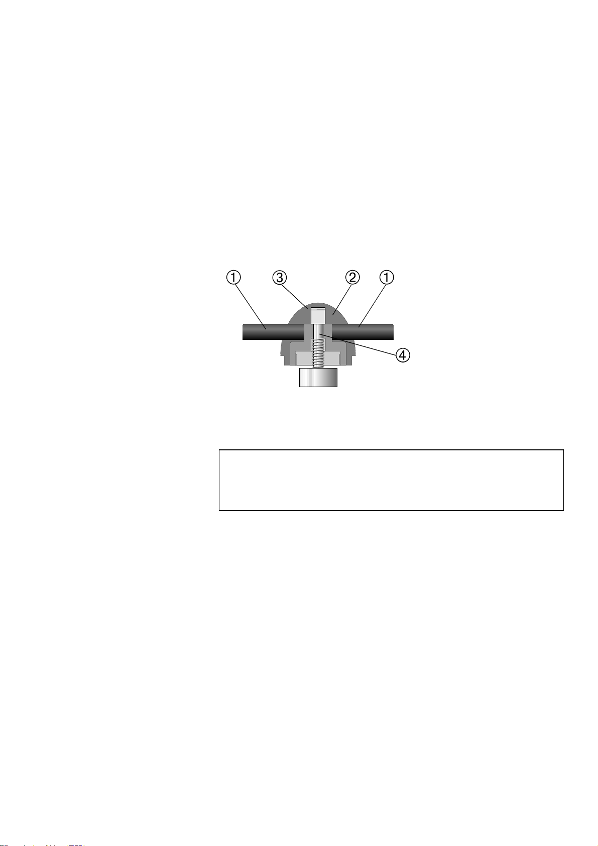
Take the cover plugs out of the ends of the handles and
unscrew them with an allen key. (pos. 1).
Remove the plastic cover (pos.2).
Lift the upper ram and remove the lock washer (pos.3).
Pull out the upper ram. Do not remove the rod (pos. 4) from
the upper ram unless absolutely necessary.
If it is necessary to remove the rod, hold the upper ram in a
vice or a similar device. The ram surface must be protected
with plastic or soft metal.
Handle
Plastic cover
Lock washer
Rod
In case there is any friction in the threads, they should be
lubricated with a dry lubricant such as MoS
2 powder or graphite.
Decalcifying the Cooling Coil in
the Mounting Unit
IMPORTANT
Please observe that the threads in the joint between the top closure and the
mounting cylinder must not be lubricated with oil or grease. As the mounting
cylinder operates at high temperatures, only a dry lubricant, resistant to high
temperatures, can be used.
When using cooling water from the mains tap in areas with a high
chalk or mineral content, deposits can build up in the cooling coil.
This may reduce the cooling effect, so once a year the cooling coil
should be decalcified.
Remove the mounting unit. (See this section.)
Flush the coil with a mild decalcifying fluid, such as that used
for coffee machines.
Flush the cooling coil with clean water.
Re-install the mounting unit.
21
LaboPress-3
Instruction Manual
Replacing the Cooling Water
Checking the Recirculation
Cooling Unit
Only relevant when a Recirculation Cooling Unit is connected:
Replace the cooling water in the Recirculation Cooling Unit at
least once a month.
Place a Disposable Plastic Container (TREPO) in the tank
and fold it over the edge.
Fill the tank with 30 l of water. NB! Too high a level of
coolant in the tank might damage the pump.
Add Struers Additive according to the instructions.
Put the lid on the tank.
Place the pump in the lid
IMPORTANT
Always maintain the correct concentration of Struers Additive in the cooling
water (percentage stated on the container of the Additive). Remember to
add Struers Additive each time you refill with water.
The cooling unit should be checked for cooling water every week
and refilled when the flushing pump cannot reach the cooling
water. Remember to add Struers Additive for Cooling Fluid: One
part of Additive for 33 parts of water.
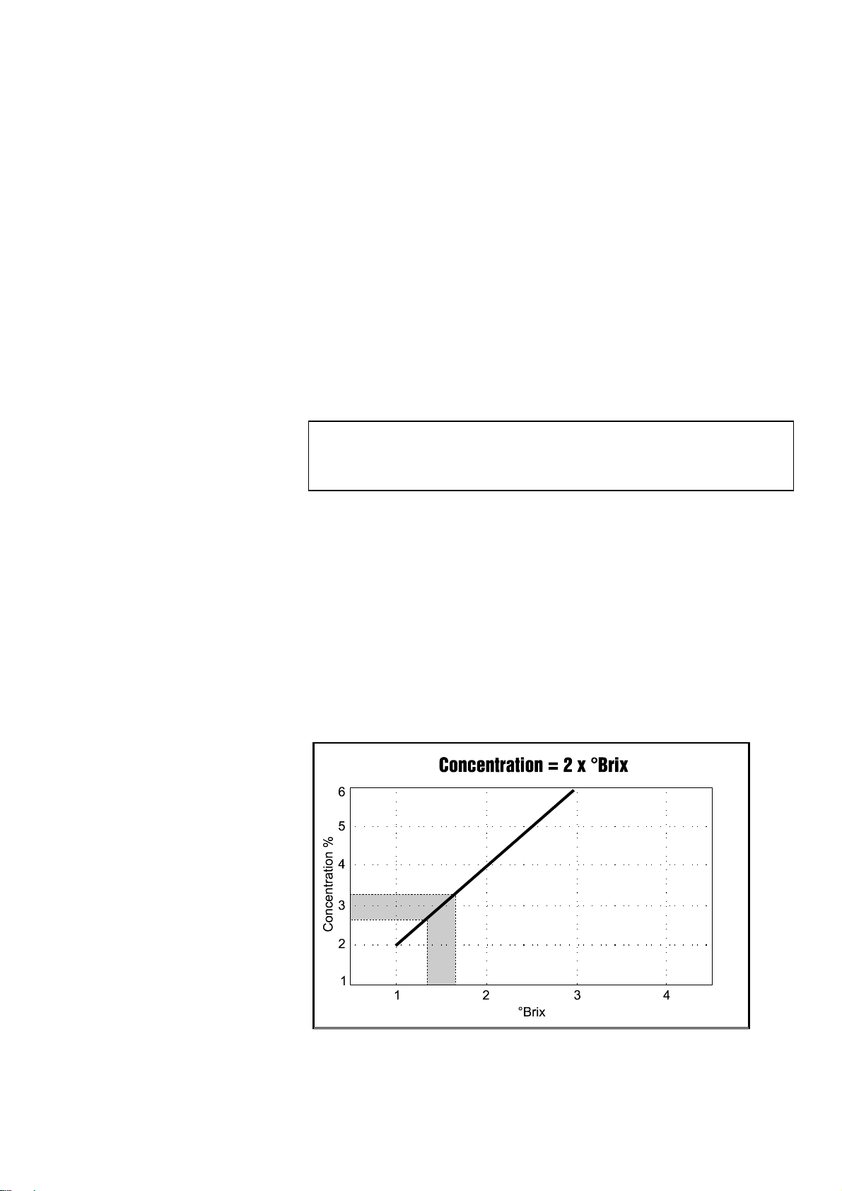
The concentration of additive should always lie between 2.7 and
3.3%; the pH should be around 9. Replace the cooling water if pH
is T 8.0.
To check the concentration of additive, use a refractometer (0-10
Brix, see diagram.). Concentration = 2 x Brix. Add Struers
Additive for Cooling Fluid if the concentration is lower than 2.7%.
Add water if the concentration is higher than 3.3%.
22

LaboPress-3
Instruction Manual
8. Technical Data
Subject Specifications
Mounting Units
(Optional)
Compression Force on piston rod Variable between 0 -
Heating
(with pressure on)
Time Variable between 0 and 15 min
Cooling
(with pressure on)
Water Supply Tap Water or
Pressure for tap water 1 - 10 bar 14.5 - 145 psi
Inlet
Supply Voltage Power phases 1
Power consumption:
Diameter
Temperature 150/180 °C 302/356°F
Time Variable between 0 and 15 min
Recirculation Cooling
Unit
Max. Total
Mounting Unit
Metric/International US
25, 30, 40, 50 mm
50 kN
1
¼" 1½"
Variable between 0 12000 Lbf
½" or ¾" ½" or ¾"
1500W
750W
Voltage/frequency: Max. continuous load
100-120V / 50Hz
100-120V / 60Hz
220-240V / 50Hz
220-240V / 60Hz
Dimensions and
Weight
Width 420 mm
Depth 580 mm
Height (Mounting Unit
and Top Closure
installed)
Weight 38 kg
10A (100V) - 12A (120V)
10A (100V) - 12A (120V)
4.5A (220V)- 5.0A (240V)
4.5A (220V)- 5.0A (240V)
420 mm
23

Placing the Specimen
Pouring Resin over the
Specimen
Installing the Top Closure
Starting the Mounting Process
Stopping the Mounting Process
Removing the Top Closure
LaboPress-3
Instruction Manual
Quick Reference Card
Press and hold RAM UP
limit.
Apply “Mould Release Agent” to the surface of the lower ram.
Place the specimen on the ram.
Press and hold RAM DOWN
limit.
Fill a suitable amount of resin into the cylinder through the
funnel.
Remove resin dust from the upper part of the mounting
cylinder.
Clean the cylindrical surface of the upper ram. Cured resin
can easily be removed without damage to the surface of the
ram using the scraper supplied.
Apply “Mould Release Agent” to all accessible surfaces of the
upper ram.
Place the top closure with the upper ram on the mounting
cylinder.
Press the top closure straight down, turning it counter-
clockwise until you hear a click.
Press the top closure down and turn it clockwise until its
lower limit.
Turn the top closure a quarter of a turn back.
Set the force.
Set the heating time.
Set the heating temperature (180/150°C).
Set the cooling time.
Press START
The machine automatically stops and relieves the pressure
when the cooling time has elapsed.
When the mounting process is finished:
Turn the top closure counter-clockwise until released from the
thread.
Press RAM UP
Place the top closure in the top closure holder.
s, and the process will run automatically.
O to raise the lower ram to its upper limit.
O to raise the lower ram to its upper
N to lower the ram to its lower
24

LaboPress-3
Gebrauchsanweisung
Handbuch Nr.: 15087003
Auslieferungsdatum 11.01.2008


LaboPress-3
Gebrauchsanweisung
Inhaltsverzeichnis Seite
Benutzerhandbuch ....................................................1
Referenzhandbuch...................................................13
Schnellinformation..................................................24
Geben Sie bitte bei technischen Anfragen oder bei der Bestellung von Ersatzteilen immer die Seriennummer
und die Spannung/Frequenz an. Diese Angaben finden Sie auf dem am Gerät angebrachten Typenschild.
Datum und Artikelnummer der Gebrauchsanweisung sind uns u.U. ebenfalls mitzuteilen. Diese Information
finden Sie auf dem Deckblatt der Gebrauchsanweisung.
Beachten Sie bitte die nachstehend genannten Einschränkungen.
Gebrauchsanweisungen: Eine von der Firma Struers veröffentlichte Gebrauchsanweisung darf nur in
Zusammenhang mit den Struers Geräten benützt werden, für die diese Gebrauchsanweisung ausdrücklich
bestimmt ist.
Wartungshandbücher: Ein von der Firma Struers veröffentlichtes Wartungshandbuch darf nur von
ausgebildeten Technikern benutzt werden, die von Struers dazu berechtigt wurden. Das Wartungshandbuch
darf nur in Zusammenhang mit dem Struers Gerät benützt werden, für das dieses Wartungshandbuch
ausdrücklich bestimmt ist.
Struers übernimmt für Irrtümer in Text und Bild der Veröffentlichungen keine Verantwortung. Wir behalten
uns das Recht vor, den Inhalt der Gebrauchsanweisungen und Wartungshandbücher jederzeit und ohne
Vorankündigung zu ändern. In den Gebrauchsanweisungen und Wartungshandbüchern können Zubehör
und Teile erwähnt sein, die nicht Gegenstand oder Teil der laufenden Geräteversion sind.
Inhalt von Gebrauchsanweisungen/Wartungshandbücher ist Eigentum der Firma Struers. Kein Teil dieser
Veröffentlichungen darf ohne schriftliche Genehmigung von Struers reproduziert werden.
Alle Rechte vorbehalten © Struers 2008.
Struers A/S
Pederstrupvej 84
DK-2750 Ballerup
Denmark
Telephone +45 44 600 800
Fax +45 44 600 801


LaboPress-3
Gebrauchsanweisung
LaboPress-3
Sicherheitshinweise
Vor Gebrauch
sorgfältig lesen
1. Der Benutzer sollte sich anhand der Gebrauchsanweisung mit dem
Gebrauch des Gerätes ausgiebig vertraut machen
2. Die Maschine muß in gut belüftetem Raum und in geeigneter
Arbeitshöhe auf einem Tisch aufgestellt werden.
3. Vergewissern Sie sich, daß die vorliegende Netzspannung mit der auf
der Rückseite des Gerätes und auf der Heiz/Kühleinheit angegebenen
Spannung übereinstimmt. Das Gerät muß geerdet sein.
4. Prüfen Sie die Wasseranschlüsse auf korrekten Anschluß und
Undichtheiten. Die Wasserversorgung muß während des Betriebs
aufgedreht sein.
Struers empfiehlt das der Wasseranschluss nach Arbeitsende
geschlossen wird.
5. Vergewissern Sie sich, daß der Abflußschlauch in geeigneter Weise an
den Abfluß angeschlossen ist.
6. Überzeugen Sie sich vor dem Start des Einbettvorgangs, ob die
Einbetteinheit korrekt montiert ist.
7. Bevor Sie die Presse in Gang setzen sollten Sie nachprüfen, ob der
obere Stempel im Einbettzylinder entweder richtig eingebaut, oder ganz
daraus entfernt ist.
8. Die Einbettpresse nicht mit höherer Kraft/Druck arbeiten lassen als es
in den Struers Anwendungshilfen für das Warmeinbetten für den
verwendeten Zylinderdurchmesser angegeben ist.
9. Bevor der Einbettzylinder im Anschluß an einen Heizzyklus geöffnet
wird, sollte er sich mindestens zwei Minuten lang abkühlen.
10. Während des Aus/Einbaus der Einbetteinheit darf das Gerät nicht in
Gang gesetzt werden.
Für die Benutzung der Geräte bzw. der Maschinen sind die Verbrauchsmaterialien von Struers vorgesehen.
Falls unzulässiger Gebrauch, falsche Installation, Veränderung, Vernachlässigung, unsachgemäße
Reparatur oder ein Unfall vorliegt, übernimmt Struers weder die Verantwortung für Schäden des Benutzers,
noch für solche am Gerät.
Die für Kundendienst und Reparatur erforderliche Demontage irgendwelcher Teile des Gerätes bzw. der
Maschine sollte immer nur von qualifiziertem Fachpersonal (Elektromechanik, Elektronik, Pneumatik usw.)
vorgenommen werden.


LaboPress-3
Gebrauchsanweisung
Benutzerhandbuch
Inhaltsverzeichnis Seite
1. Zu Beginn
Packungsinhalt prüfen ..................................................................... 2
LaboPress-3................................................................................ 2
Einbetteinheit............................................................................ 2
LaboPress-3 auspacken .................................................................... 2
LaboPress-3 aufstellen ..................................................................... 2
Transportschraubkappe ................................................................... 2
LaboPress-3 kennenlernen............................................................... 3
Geräuschpegel................................................................................... 4
Netzanschluß ....................................................................................4
Wasseranschluß................................................................................ 4
Wasserzufluß ............................................................................. 4
Wasserabfluß ............................................................................. 4
Einbetteinheit zusammenbauen...................................................... 5
Abdeckung abnehmen ............................................................... 5
Unteren Stempel einbauen ....................................................... 5
Einbetteinheit montieren.......................................................... 5
Abdeckung montieren ...............................................................6
Staubschutzring anbringen....................................................... 6
Einbetteinheit zerlegen .................................................................... 6
Unteren Stempel absenken....................................................... 6
Staubschutzring abnehmen ...................................................... 6
Abdeckung abnehmen ............................................................... 6
Einbetteinheit ausbauen..................................................................7
Entfernen des Unterstempels .......................................................... 7
Einbetteinheit auswechseln ............................................................. 7
2. Grundzüge der Bedienung
Gebrauch der Bedienelemente......................................................... 8
Bedienungsfeld des LaboPress-3 .............................................. 8
Akustische Signale .................................................................... 8
Hauptschalter ............................................................................ 8
Probe einlegen................................................................................. 10
Einbettmittel über die Probe gießen ......................................10
Zwei Proben einlegen...................................................................... 10
Verschluß aufsetzen .......................................................................11
Einbettvorgang starten ..................................................................12
Vorheizen mit niedrigem Druck .............................................12
Einbettvorgang stoppen .................................................................12
Verschluß abnehmen ...................................................................... 12
1

Packungsinhalt prüfen
LaboPress-3
Einbetteinheit
LaboPress-3 auspacken
LaboPress-3 aufstellen
Transportschraubkappe
LaboPress-3
Gebrauchsanweisung
1. Zu Beginn
Folgende Gegenstände sollten in der Verpackung enthalten sein:
1 LaboPress-3 Gerät
1 Druckschlauch
1 Filterdichtung
1 Dichtung
1 Reduktionsring mit Dichtung
2 Meßlöffeln für Einbettmittel
1 Trichter
1 Luftfilter
1 Manualsatz
1 Einbetteinheit
1 Verschluß mit oberem Stempel
1 Unterer Stempel
1 Stempelstift
1 Staubschutzring
1 Anti-Haftmittel (FASTI)
1 Schaber (PROAN)
Nehmen Sie LaboPress-3 vom Boden der Verpackung ab; dazu
entfernen Sie die vier Schrauben von der Unterseite her.
LaboPress-3 sollte auf einem stabilen Tisch in geeigneter
Arbeitshöhe aufgestellt werden. Das Gerät muß sich in Nähe des
Netzanschlusses, der Wasserversorgung und des Wasserabflusses
befinden. Falls eine Wasserkühlung verwendet wird, muß für die
Umlaufkühlung (TRECI) unter dem Tisch ausreichend Platz zur
Verfügung stehen.
Folgender Vorgang muß duchgeführt werden, bevor das Gerät in
Betrieb genommen wird:
Die Transportschraubkappe mit dem Luftfilter austauschen
um den Druck im hydraulischen System auszugleichen.
Die Transportschraubkappe ist unter dem Deckel für die Einbetteinheit
angebracht.
2

LaboPress-3
Gebrauchsanweisung
LaboPress-3 kennenlernen
Nehmen Sie sich einen Augenblick Zeit, um Lage und
Bezeichnung aller Teile des LaboPress-3 kennenzulernen.
➁
➄
➃
➅
➀
➆
➂
Bedienungsfeld
Verschluß
Hauptschalter
Einbetteinheit
Staubschutz
Abdeckung der Einbetteinheit
Halterung für den Verschluß
3

LaboPress-3
Gebrauchsanweisung
Geräuschpegel
Netzanschluß
Wasseranschluß
Wasserzufluß
Wasserzufluß
Wasserabfluß
Wasserabfluß
Der Geräuschpegel der Maschine beträgt etwa 60 dB (A),
gemessen bei laufender Pumpe in einer Entfernung von 1,0
m/39.4" zum Gerät.
LaboPress-3 wird mit elektrischem Anschlußkabel geliefert.
Bringen Sie einen Stecker am Kabel an, und schließen Sie die
Maschine an das Netz an:
Braun: Phase
Blau: Neutral
Gelb/grün: Erde
WICHTIG
Das Typenschild des Gerätes gibt die zulässige Spannung an. Prüfen Sie
bitte nach, ob diese mit der vorliegenden Netzspannung übereinstimmt. Das
Gerät darf nicht gestartet werden bevor die Transportschraubkappe nicht
gegen den Luftfilter ausgetauscht wurde.
Kühlwasser kann aus dem Leitungsnetz oder einer
Umlaufkühlung bezogen werden.
Bringen Sie den Druckschlauch am Wassereintritt (Pos. 1) auf der
Rückseite des Gerätes an:
Legen Sie die Filterdichtung so in die Verschraubung der
Kupplung, daß deren flache Seite am Druckschlauch anliegt.
Ziehen Sie die Verschraubung der Kupplung ausreichend fest
an.
➃
Das andere Ende des Druckschlauchs verbinden Sie mit dem
➀
Wasserhahn der Kaltwasserversorgung:
Falls erforderlich, schrauben Sie den Reduktionsring samt
➄
➁
Dichtung an den Wasserhahn.
Legen Sie die Dichtung ein, und ziehen Sie die
Verschraubung der Kupplung ausreichend fest an.
WICHTIG
Nur an die Kaltwasserversorgung anschließen
Führen Sie den Rücklaufschlauch (Pos. 2) zum Abfluß.
Vergewissern Sie sich, daß er auf ganzer Länge ein
gleichmäßiges Gefälle aufweist und nirgendwo abgeknickt ist.
Bringen Sie den Abflußschlauch am Abflußsystem an.
4

LaboPress-3
A
Gebrauchsanweisung
Einbetteinheit zusammenbauen
bdeckung abnehmen
Unteren Stempel einbauen
Einbetteinheit montieren
Den Schnappverschluß lösen (Pos. 4).
Durch leichten Druck rechts und links auf die Abdeckung
kommt diese frei; heben Sie sie ab.
➃
➀
➄
➁
Schnappverschluß
Den Untertempel auf die Stempelstange anbringen
Den Unterstempel so drehen, daß die Löcher in der Stange
und der Stempel übereinstimmen und setzen Sie den
Stempelstift ein
Vergewissern Sie sich, daß der Stift nicht herausragt.
WICHTIG
Der Achszapfen ist ein Teil des Sicherheitsmechanismus des Gerätes, um
das Gerät gegen Schäden zu schützen. Sehen Sie: Wartung. Falls er bricht
darf er nur mit einem originalen Struers Ersatzstift erstattet werden, da die
Sicherheitsmechanismen sonst nicht optimal sind.
➀
➂
➃
➁
➄
Einbettzylinder
Feststellschraube
Obere Schnellkupplung für das Kühlwasser
Untere Schnellkupplung für das Kühlwasser
Stecker
WICHTIG
Beim Einbau der Einbetteinheit darf das Gerät nicht eingeschaltet werden.
5

A
bdeckung montieren
A
➃
➀
➄
➁
Schnappverschluß
Staubschutzring anbringen
Einbetteinheit zerlegen
Unteren Stempel absenken
Staubschutzring abnehmen
bdeckung abnehmen
LaboPress-3
Gebrauchsanweisung
Schrauben Sie die Feststellschraube etwa 10 mm heraus.
Führen Sie den Einbettzylinder so über den unteren Stempel,
daß die Feststellschraube die in der Zeichnung gezeigte Lage
einnimmt.
Drehen Sie die Einbetteinheit im Uhrzeigersinn bis sie stoppt.
Ziehen Sie die Feststellschraube vollständig an.
Bringen Sie den Schlauch mit dem geraden Kupplungsstück
an der unteren Schnellkupplung der Einbetteinheit (Pos. 4)
an, und stellen Sie die Verbindung durch Zusammenschieben
der Kupplungsstücke her. Achten Sie darauf, daß der Ring bis
zum Anschlag in die Schnellkupplung hineingeschoben wird.
Bringen Sie den Schlauch mit dem abgewinkelten
Kupplungsstück an der oberen Schnellkupplung der
Einbetteinheit (Pos. 3) an, und stellen Sie die Verbindung
durch Zusammenschieben der Kupplungsstücke her. Achten
Sie darauf, daß der Ring bis zum Anschlag in die
Schnellkupplung hineingeschoben wird.
Verbinden Sie den Stecker (Pos. 5) mit der Stellvorrichtung.
Ziehen Sie die Überwurfmutter an.
Haken Sie die vorne liegende Klaue der Abdeckung in die
entsprechende Aussparung am Rand des Gehäuses ein.
Führen Sie die beiden seitlich an der Abdeckung liegenden
Klauen in das Gerätegehäuse ein. Drücken Sie leicht auf die
Seiten der Abdeckung.
Die Rückseite des Deckels festdrücken, so daß der
Schnappverschluß einschnappt.
Bringen Sie den Staubschutzring um den Einbettzylinder herum
an. Die konkave Seite soll dabei nach oben zeigen.
Schalten Sie das Gerät mit dem Hauptschalter ein.
Mit der Taste STEMPEL AB
N bewegen Sie den unteren
Stempel in seine tiefste Lage.
Nehmen Sie den Staubschutzring ab.
Den Schnappverschluß lösen (Pos. 4).
Durch leichten Druck rechts und links auf die Abdeckung
kommt diese frei; heben Sie sie ab.
6

LaboPress-3
Gebrauchsanweisung
Einbetteinheit ausbauen
➀
➂
➃
➁
➄
Entfernen des Unterstempels
Einbetteinheit auswechseln
WICHTIG
Beim Ausbau der Einbetteinheit darf das Gerät nicht eingeschaltet werden.
Einbettzylinder
Feststellschraube
Obere Schnellkupplung für das Kühlwasser
Untere Schnellkupplung für das Kühlwasser
Stecker
Lösen Sie die Überwurfmutter der Steckverbindung. Ziehen
Sie den Stecker (Pos. 5).
Nehmen Sie den Schlauch mit dem abgewinkelten
Kupplungsstück von der oberen Schnellkupplung der
Einbetteinheit (Pos. 3). Ziehen Sie den Ring ab. Warten Sie 5
Sekunden lang, bis das Wasser aus der Kühlschlange
ausgeflossen ist.
Nehmen Sie den Schlauch mit dem geraden Kupplungsstück
von der unteren Schnellkupplung der Einbetteinheit (Pos. 4).
Ziehen Sie den Ring ab.
Drehen Sie die Feststellschraube etwa 10 mm heraus.
Drehen Sie die Einbetteinheit so lange gegen den Uhrzeiger,
bis sie stoppt.
Heben Sie die Einbetteinheit ab.
Den Stempelstift aus dem Unterstempel drücken.
WICHTIG
Der Achszapfen ist ein Teil des Sicherheitsmechanismus des Gerätes, um
das Gerät gegen Schäden zu schützen. Sehen Sie: Wartung. Falls er bricht
darf er nur mit einem originalen Struers Ersatzstift erstattet werden, da die
Sicherheitsmechanismen sonst nicht optimal sind.
Folgen Sie den Anweisungen zum Aus/Einbau der Einbetteinheit.
7

Gebrauch der Bedienelemente
A
Bedienungsfeld des
LaboPress-3
LaboPress-3
Gebrauchsanweisung
2. Grundzüge der Bedienung
180°C
LaboPress-3
150°C
kustische Signale
Hauptschalter
8
Ein kurzer Ton zeigt an, daß die erfolgte Tastatureingabe
registriert wurde.
Ein langer Ton weist darauf hin, daß der Befehl dieser Taste
augenblicklich nicht zur Verfügung steht.
Drei lange Töne signalisieren die Beendigung des
Einbettvorgangs.
➄
➃
➅
➀
➁
➆
c Bedienungsfeld
e Hauptschalter
➂

LaboPress-3
Gebrauchsanweisung
Pos. Nr. Taste Funktion Pos. Nr. Taste Funktion
HAUPTSCHALTER
Schaltet die Stromversorgung
ein/aus. Der Hauptschalter liegt
rechts am Gehäuse der Maschine.
ANZEIGE
HEIZUNG
¹
Leuchtet bei eingeschalteter
Heizung.
NETZ
POWER
START
s
STOP
o
STEMPEL
AUF
O
STEMPEL
AB
N
Leuchtet bei eingeschaltetem Netz.
Startet den automatischen
Einbettvorgang.
Stoppt den Einbettvorgang mit
automatischem Druckabfall. Stoppt
die Bewegung des unteren
Stempels.
Startet Aufwärtsbeweg. des unteren
Stempels. Nach dem Start: stoppt
die Aufwärtsbewegung des unteren
Stempels. Stempel stoppt autom.
bei Erreichen der obersten Lage.
Startet Abwärtsbeweg. des unteren
Stempels. Nach dem Start: stoppt
die Abwärtsbewegung des unteren
Stempels. Stempel stoppt autom. bei
Erreichen der unterste Lage.
HEIZEN
1
ANZEIGE
HEIZEN
2
HEIZEN
3
ANZEIGE
HEIZEN
4
KÜHLUNG
180°C
180°C
150°C
150°C
¸
Heiztemperatur von180°C wird
eingestellt.
Leuchtet, wenn die Heiztemperatur
180°C eingestellt ist.
Heiztemperatur von 150°C wird
eingestellt.
Leuchtet, wenn die Heiztemperatur
150°C eingestellt ist.
Knopf zum Einstellen der Kühlzeit..
KRAFT
f
HEIZUNG
¹
Knopf zum Einstellen der Kraft
(Druck).
Knopf zum Einstellen der Heizzeit.
5
ANZEIGE
KÜHLUNG
6
ÜBERLAST
OVERLOAD
¸
Leuchtet bei eingeschalteter
Kühlung.
Leuchtet bei Überlastung des
Motors.
9

LaboPress-3
Gebrauchsanweisung
Probe einlegen
Einbettmittel über
die Probe gießen
Zwei Proben einlegen
Drücken und halten Sie die Taste STEMPEL AUF
unteren Stempel in seine oberste Lage zu fahren.
Tragen Sie das Anti-Haftmittel auf die Oberfläche des
unteren Stempels auf.
Legen Sie die Probe auf den unteren Stempel. Die Probe muß
sauber, trocken und fettfrei sein. Damit Risse im
Einbettmittel vermieden werden, muß der Abstand der Probe
von der Zylinderwand mindestens 3 mm betragen.
Drücken und halten Sie die Taste STEMPEL AB
unteren Stempel in seine unterste Lage zu fahren.
Mit Hilfe des beiliegenden Trichters gießen Sie die geeignete
Menge Einbettmittel in den Zylinder.
Es muß immer genügend Resin im Zylinder sein um die Probe
auch unter Druck zu decken. Bedenken Sie bitte daß das Volumen
des granulieren Resines kleiner wird, wenn es unter Druck
kommt. Ist zu wenig Resin eingefüllt können die Stempel auf die
Probe drücken und der Zylinder kann zerstört werden
WICHTIG
Damit das Anti-Haftmittel ein Kleben des Einbettmittels an der Oberfläche
verhindert, muß es immer in einer dünnen Schicht auf die Oberflächen der
Einbettstempel aufgetragen werden. Mit dem Struers AntiStick kann eine
dünne Schicht Pulver auf die Stempel getupft werden.
Gehen Sie vor, wie oben unter Proben einlegen beschrieben
ist.
Tragen Sie das Anti-Haftmittel auf die beiden Oberflächen
des Zwischenstempels auf.
Legen Sie den Zwischenstempel oben auf das Einbettmittel.
Legen Sie die zweite Probe auf den Zwischenstempel, und
füllen Sie die geeignete Menge Einbettmittel in den Zylinder.
Nochmals, versichern Sie sich, daß genügend Resin eingefüllt ist!
O, um den
N, um den
10

LaboPress-3
Gebrauchsanweisung
Verschluß aufsetzen
Entfernen Sie den Staub des Einbettmittels vom oberen Teil
des Einbettzylinders.
Die zylindrische Oberfläche des oberen Stempels reinigen.
Gehärtenes Einbettmittel läßt sich einfach entfernen, ohne
die Oberfläche des Stempels zu beschädigen, wenn der
mitgelieferte Schaber verwendet wird.
Tragen Sie das Anti-Haftmittel auf die Oberfläche des oberen
Stempels auf.
Setzen Sie den Verschluß mit dem oberen Stempel auf den
Einbettzylinder.
Drücken Sie den Verschluß nach unten und drehen Sie ihn
dabei im Uhrzeigersinn bis Sie ein Klicken hören.
Drehen Sie den Verschluß eine Vierteldrehung zurück.
WICHTIG
Falls der Stempel nicht in den Zylinder paßt, kontrollieren Sie ob sich
ausgehärtetes Einbettmittel auf Stempel und Zylinder befindet. Die Toleranz
des Spiels zwischen Zylinder und Stempel ist ziemlich gering, weshalb
selbst geringe Einbettmittelrückstände Probleme verursachen können.
11

LaboPress-3
Gebrauchsanweisung
Einbettvorgang starten
Vorheizen mit niedrigem Druck
Einbettvorgang stoppen
Stellen Sie die Kraft ein.
Stellen Sie die Heizzeit ein.
Stellen Sie die Heiztemperatur ein (180/150°C).
Stellen Sie die Kühlzeit ein.
Drücken Sie die Taste START
automatisch ab.
Der Ablauf des Einbettvorgangs kann mit Hilfe der
Kontrollanzeigen für Heizung und Kühlung verfolgt werden.
Stellen Sie die Kraft auf einen niedrigen Wert. Erhöhen Sie die
Kraft auf den richtigen Wert nach Ablauf der gewünschten
Vorheizzeit.
Nach Ablauf der Kühlzeit stoppt die Maschine automatisch
und der Druck wird abgebaut. Während des Einbettvorgangs
können Sie die Maschine jederzeit mit der Taste STOP
stoppen.
Bevor Sie den Einbettzylinder nach einer Heizperiode öffnen,
sollte er sich mindestens 2 Minuten lang abkühlen. Beachten Sie bitte, daß
andernfalls die Einbettung beschädigt werden könnte.
s, und der Vorgang läuft
o
Verschluß abnehmen
Wenn der Einbettvorgang beendet ist:
Drehen Sie den Verschluß im Gegenuhrzeigersinn, und
nehmen Sie ihn aus der Verschraubung heraus.
Mit der Taste STEMPEL AUF
Stempel in seine höchste Lage.
Legen Sie den Verschluß in die dafür vorgesehene Halterung.
O fahren Sie den unteren
12

LaboPress-3
Gebrauchsanweisung
Referenzhandbuch
Inhaltsverzeichnis Seite
1. Details und Besonderheiten der Bedienung
Installation...................................................................................... 14
Umlaufkühleinheit (Optional) ................................................ 14
Steckverbindung für Umlaufkühleinheit............................... 14
2. Struers Metalog Guide™
............................................... 15
3. Anwendungshilfen für das Warmeinbetten
.......... 15
4. Zubehör
.................................................................................. 16
5. Verbrauchsmaterialien
................................................... 17
6. Fehlersuche
......................................................................... 18
7. Wartung
Tägliche Pflege................................................................................ 20
Monatliche Reinigung ....................................................................20
Raum unter dem unteren Stempel reinigen .......................... 20
Stempel reinigen............................................................................. 20
Entfernen des Oberstempels.......................................................... 21
Schmieren der Gewinde des Verschlusses ....................................21
Entkalken der Kühlspirale in der Einbetteinheit......................... 21
Kühlwasser ersetzen ......................................................................22
Umlaufkühleinheit überprüfen...................................................... 22
8. Technische Daten
............................................................. 23
13

Installation
Umlaufkühleinheit (Optional)
TRECI
ROPRE
LaboPress-3/
ProntoPress-10/ProntoPress-20
Steckverbindung für
Umlaufkühleinheit
Abflußschlauch
Steckverbindung für
Umlaufkühlung
LaboPress-3
Gebrauchsanweisung
1. Details und Besonderheiten der Bedienung
Die Umlaufkühleinheit (TRECI) wird über einen Adapter
(ROPRE) an die Einbettpresse angeschlossen.
Das Kabel verbinden, das von der TRECI-Pumpe kommt, mit
ROPRE, wie es das Anschlußdiagramm für ROPRE zeigt.
Den Stecker des Anschlußkabels von ROPRE stecken Sie in
die Steckverbindung (Pos. 5) auf der Rückseite der
Einbettpresse.
Das Kabel schließen, das von ROPRE kommt, an das Netz an.
Vergewissern Sie sich, daß die Pumpe in der Richtung rotiert,
die auf der Pumpe angegeben ist. Falls die Drehrichtung nicht
stimmt, vertauschen Sie zwei der Phasen des
➃
➀
➄
➁
Pumpenanschlusses an der Umlaufkühleinheit (nur
dreiphasige Version).
Ersetzen Sie das Austrittsrohr der TRECI-Pumpe durch ein
Rückschlagventil mit Krümmer und sechseckigem
Übergangseinschraubstutzen von ROPRE. Es empfiehlt sich,
die Gewinde abzudichten.
Verbinden Sie den Druckschlauch der Einbettpresse mit dem
Einschraubstutzen. Denken Sie daran, die Dichtung
einzubauen.
Führen Sie den Abflußschlauch (Pos. 2) zum Einlaß am
TRECI. Vergewissern Sie sich, daß der Abflußschlauch auf
der gesamten Länge Gefälle besitzt und nicht geknickt ist.
Verbinden Sie den Abflußschlauch mit dem Einlaß am
TRECI.
14

LaboPress-3
Gebrauchsanweisung
2. Struers Metalog Guide™
Der Struers Metalog Guide™ bietet für die meisten gängigen
Materialien Präparationsmethoden an, die sich an der einfachen
Untersuchung zweier Schlüsseleigenschaften orientieren: Härte
und Duktilität. Die richtige Methode ist ebenso leicht
herauszufinden, wie die Wahl der Verbrauchsmaterialien. Wenn
Sie für Ihre vorliegenden Proben die geeignete
Präparationsmethode suchen, sollten Sie immer den Struers
Metalog Guide™ zu Rate ziehe.
Der Struers Metalog Guide™ umfaßt 6 hilfreiche Kapitel:
Metalogram
Metalog Methoden
Präparationsphilosophie
Metalog Verfahren
Metalog Master
Metalog Code
Führt Sie rasch, sicher und ohne Umwege zur richtigen
Präparationsmethode.
Eine komplette Sammlung von Präparationsmethoden, die auf
der reichen materialographischen Erfahrung von Struers beruht
und dabei die Verbrauchsmaterialien von Struers berücksichtigt.
Die Grundlagen moderner Probenpräparation aus Expertensicht.
Materialographische Präparation logisch von A-Z erklärt.
Dieses Expertensystem berät Sie nicht nur bei der Problemlösung
von Präparationsschwierigkeiten, sondern versorgt Sie auch mit
breitem Hintergrundwissen über die Verfahren mechanischer
Präparation.
Hilft Ihnen beim schnellen Zugriff auf die passenden
Verbrauchsmaterialien zur ausgewählten Methode.
Struers Metalog Guide
Ihr ausführlicher Ratgeber für materialographische Probenpräparation.
Fragen Sie Ihren Fachhändler nach einem kostenlosen Exemplar des
Metalog Guide™
3. Anwendungshilfen für das Warmeinbetten
Die Struers Anwendungshilfen für das Warmeinbetten liefern
Ihnen Einbettdaten, Tips und Tricks oder Besuchen Sie die
Struers Website auf http://www.struers.com
Abschnitt unter Know How.
und sehen Sie den
15

LaboPress-3
Gebrauchsanweisung
4. Zubehör
Gegenstand Beschreibung Kennwort
Einbetteinheit
bestehend aus Zylinder, unterem und oberem Stempel,
Heiz/Kühleinheit und Verschluß
Zwischenstempel
für die gleichzeitige Herstellung von 2 Einbettungen
Umlaufkühleinheit
Adapter
für die Umlaufkühleinheit für den Anschluß der
Umlaufkühleinheit (TRECI) an LaboPress-3
25 mm Durchm.
30 mm Durchm.
1 ¼" Durchm.
1 ½" Durchm.
40 mm Durchm.
50 mm Durchm.
25 mm Durchm.
30 mm Durchm.
1 ¼" Durchm.
1 ½" Durchm.
40 mm Durchm.
50 mm Durchm.
TRECI
ROPRE
CYNMI
CYNTE
CYNQU
CYNHA
CYNIF
CYNAM
CYLDO
CYLDO
CYLDO
CYLDO
CYLDO
CYLDO
16

LaboPress-3
Gebrauchsanweisung
5. Verbrauchsmaterialien
Name Anwendung
ConduFast
(Resin 1)
SpeciFast
(Resin 3)
PolyFast Randschärfe Sehr geringe Schrumpfung
Untersuchung im
IsoFast
(Resin 4)
DuroFast
(Resin 5)
MultiFast Routineuntersuchungen
MultiFast
Green
MultiFast
Brown
Name Anwendung
Pre-Mount
Elektrolytisches Polieren Elektrisch leitend
Glasklare Einbettungen
Poröse Proben
Isolieren der Oberfläche bei
ConduFast
Rasterelektronenmikroskop
Randschärfe
Planheit
Randschärfe
Planheit
Auffüll Einbettmittel
Routineuntersuchungen
Farbmarkierung
Routineuntersuchungen
Farbmarkierung
Serieneinbettung von
unkomplizierten Formen
Produkt Anwendung Material Inhalt Kennwort
Mould Release
Wax
AntiStick
Um Haftung der Einbettung
an den Stempel zu
vermeiden
Um Haftung der Einbettung
an den Stempel zu
vermeiden
Spezifische Eigenschaften Material Inhalt Kenn-
Sehr geringe Schrumpfung
Transparent
Mittlere Schrumpfung
Mittlere Abtragsrate
Elektrisch leitend
Niedrige Emission in der
Vakuumkammer
Geringe Schrumpfung
Niedrige Abtragsrate
Sehr geringe Schrumpfung
gute Haftung
Mittlere Abtragsrate
Geringe Schrumpfung
Mittlere Abtragsrate
Geringe Schrumpfung
Mittlere Abtragsrate
Geringe Schrumpfung
Mittlere Abtragsrate
Spezifische Eigenschaften Material Inhalt Kenn-
Einfach zu handhaben
Geringe Schrumpfung
Mittlere Abtragsrate
Wachs 24 g PREWA
Sehr feines Stearatpulver 8 g FASTI
Akryl mit Eisenpulver
Füllstoff
Thermoplastisch, Grau
Akryl
Thermoplastisch
Phenol mit Kohle Füllstoff
Warmaushärtend, Schwarz
Dialylphtalat mit Glasfaser
Füllstoff
Warmaushärtend, Grün
Epoxid mit Mineral Füllstoff
Warmaushärtend, Schwarz
Phenol mit Holzmehl
Füllstoff
Warmaushärtend, Schwarz
Phenol mit Holzmehl
Füllstoff
Warmaushärtend, Grün
Phenol mit Holzmehl
Füllstoff
Warmaushärtend, Braun
Phenol mit Holzmehl
Füllstoff
Warmaushärtend, Schwarz
In Tablettenform
1 kg RESFE
1,5 kg
7,5 kg
25 kg
1 kg
7,5 kg
1 kg
7,5 kg
1 kg
7,5 kg
2,5 kg
7,5 kg
25 kg
2,5 kg
7,5 kg
25 kg
2,5 kg
7,5 kg
25 kg
25 mm/
1"
Durchm.
etwa.
1100 Stk.
10 kg
30 mm/
1.1/4"
Durchm.
etwa.
760 Stk.
10 kg
40 mm/
1 ½"
Durchm.
etwa.
460 Stk.
10 kg
wort
RESTH
RESYV
RESFA
FAPSA
FAPME
RESDI
RESTY
RESIF
RESEN
RESRU
RESUK
RESLA
FAGSA
FAGME
FAGLA
FABSA
FABME
FABLA
wort
RESUN
RESGI
RESAM
17

LaboPress-3
Gebrauchsanweisung
6. Fehlersuche
Anzeige/Fehler Grund Maßnahme
Fehlermeldung
Überlastung Motor überlastet Lassen Sie den Motor abkühlen und starten
Sie die Einbettpresse erneut.
Falls dies nicht hilft, rufen Sie den Struers
Kundendienst an.
Akustische Signale
Langer Ton. Befehl steht nicht zur Verfügung. Lesen Sie in der Gebrauchsanweisung das
Kapitel Grundzüge der Bedienung.
Maschinenprobleme
Start nicht möglich Heiz- und Kühlzeit sind auf Null Stellen Sie die richtige Zeit ein.
Druck unzureichend. Kraft/Druck sind falsch eingestellt. Stellen Sie die Parameter richtig ein.
Drucksystem schadhaft. Rufen Sie den Struers Kundendienst an.
Heizung unzureichend. Zeiten für Vorwärmen/Heizen sind
falsch eingestellt.
Heizsystem schadhaft. Rufen Sie den Struers Kundendienst an.
Kühlung unzureichend. Kühlzeit falsch eingestellt. Stellen Sie den Parameter richtig ein.
Wasserhahn des Leitungswassers ist
nicht/zu wenig geöffnet.
Filter am Wassereintritt ist verstopft.
Wassertemperatur zu hoch.
Wasserstand in der Umlaufkühleinheit
zu gering. Wassertemperatur zu hoch.
Kühlsystem schadhaft. Rufen Sie den Struers Kundendienst an.
Kühlwasser tropft unten aus
der Maschine.
Der Verschluß kann nicht in
das Gewinde des Einbettzylinders eingedreht werden
Der Oberstempel ist zu warm. Lassen Sie den Verschluß und den
Ausgehärtetes Resin im Einbettzylinder. Den Einbettzylinder mit einer Metallbürste
Ausgehärtetes Resin sitzt auf dem
Der Verschluß ist heruntergefallen und
Schnellkupplung ist nicht richtig
montiert.
Der Verschluß ist nicht richtig montiert Den Verschluß direkt nach unten drücken und
Oberstempel
die Kante des Oberstempels ist
beschädigt.
Stellen Sie die Parameter richtig ein.
Wasserhahn öffnen.
Filter reinigen.
Wasser bis zur Füllhöhe nachfüllen. Siehe
Kapitel Wartung.
Nehmen Sie die Abdeckung von der
Einbetteinheit und prüfen Sie die Anschlüsse
der Schnellkupplungen.
ihn gegen den Uhrzeigersinn drehen bis ein
Klicken zu hören ist. Dann den Verschluß im
Uhrzeigersinn drehen.
Oberstempel abkühlen.
Einbetttemperatur herabsetzen
reinigen
Den Stempel mit dem mitgelieferten Schaber
reinigen.
Ersetzen Sie den Oberstempel.
18

LaboPress-3
Gebrauchsanweisung
Anzeige/Fehler Grund Maßnahme
Das Gewinde zwischen Verschluß und
Zylinder oder der Oberstempel sind
beschädigt.
Der Verschluß kann nicht völlig
zugedreht werden
Die Scheibe für die Wärmeisolation auf
Der Verschluß kann nicht
abgenommen werden.
Schmutz auf dem Gewinde des
Verschlusses und des Zylinders
dem Oberstempel hat einen größeren
Durchmesser als der Oberstempel
Der Verschluß ist vor dem Start des
Einbettvorgangs nicht um ¼ Drehung
zurückgedreht worden.
Ausgehärtetes Einbettmaterial befindet
sich auf der Zylinderoberfläche des
oberen Stempels.
Die Gewindegänge des Verschlusses
sind mit Schmutz verklebt.
Den Oberstempel abnehmen (Sehen Sie
Abschnitt Wartung) Beide Möglichkeiten
erproben um festzustellen wo das Problem
liegt:
Den Verschluß ohne Oberstempel
montieren. Ist das nicht möglich einen
Struers Servicemitarbeiter bestellen
Den Oberstempel alleine in den Zylinder
einsetzen. Ist das nicht möglich einen
Struers Servicemitarbeiter bestellen
Die Gewinde reinigen. Nur trockenes
Schmierpulver verwenden
Bestellen Sie einen Struers Service Techniker
Abnehmen des Verschlusses:
- den Unterstempel mehrere Male hoch und
runter bewegen.
Wenn dies nichts nutzt:
-Die Heizung ca. 1 min. einschalten
Wenn die nichts nutzt:
- Den Einbettdruck auf Null stellen.
- Die Heiz und Kühlzeit auf 15 min stellen.
- Einen Einbettvorgang durchführen
Wenn die nichts nutzt:
- Die beiden Handgriffe vom Verschluß
abschrauben.
- Den Kunststoffdeckel vom Verschluß
abschrauben (Sehen Sie bitte unter Wartung).
--Den Verschluß mit einem Gabelschlüssel
lösen.
19

Tägliche Pflege
Monatliche Reinigung
Raum unter dem unteren
Stempel reinigen
Stempel reinigen
LaboPress-3
Gebrauchsanweisung
7. Wartung
Reinigen Sie alle zugänglichen Oberflächen mit einem
feuchten Tuch.
Beim Einbetten kann ausgehärtetes Resin vom Unterstempel
fallen und sich darunter aufbauen. Das ausgehärtete
Einbettmittel muß entfernt werden, damit das Gerät nicht
zerstört wird. Der Achszapfen im Unterstempel ist so entwickelt,
daß er bricht. bevor das Gerät ernsthaft beschädigt wird.
Nehmen Sie die Einbetteinheit ab, wie dies im
entsprechenden Abschnitt beschrieben ist.
Entfernen Sie das ausgehärtete Einbettmittel unter dem
unteren Stempel mit einem Tuch oder einer weichen Bürste.
Bringen Sie die Einbetteinheit wieder an, wie dies im
entsprechenden Abschnitt beschrieben ist.
Überzeugen Sie sich vor jedem Einbettvorgang davon, daß aus
vorangehender Benutzung kein Einbettmittel auf den Stempeln
zurückgeblieben ist. Der Rand des Oberstempels und evtl. des
Zwischenstempels soll ebenfalls gereinigt werden, da
Einbettmittelreste Probleme beim Anbringen des Stempel im
Zylinder geben können. Ausgehärtetes Einbettmittel wird leicht
mit dem Schaber, der beigelegt ist, entfernt.
Falls die polierten Oberflächen der Stempel verkratzt sind, bauen
Sie diese aus, und polieren Sie sie mit 6 oder 3µm Diamanten auf
einem Poliertuch.
WICHTIG
Polieren Sie nicht die Seiten der Stempel. Falls diese sehr stark verkratzt
sind, müssen sie ersetzt werden.
20

LaboPress-3
Gebrauchsanweisung
Entfernen des Oberstempels
Schmieren der Gewinde des
Verschlusses
Entkalken der Kühlspirale in der
Einbetteinheit
Die Deckel am Ende der Handgriffe entfernen und die
Handgriffe mit einem Schraubenschlüssel abschrauben (Pos.
1).
Die Kunststoffkappe entfernen (Pos. 2).
Den Oberstempel anheben und die Unterlegscheibe entfernen
(Pos. 3).
Den Oberstempel herausziehen. Nicht den Stab (Pos. 4) aus
den Oberstempel entfernen, es sei denn es ist absolut
notwendig.
Muß der Stab entfernt werden soll der Oberstempel in einem
Schraubstock oder ähnlichen anbringen. Die
Stempeloberfläche muß dann geschützt werden.
Handgriff
Plastikkappe
Schraube
Stab
Falls Reibung in den Gewinden entsteht sollten Sie mit einem
trockenen Schmiermittel wie MoS
2 Pulver oder Graphit
geschmiert werden.
WICHTIG
Die Gewinde dürfen nicht mit Öl oder Fett geschmiert werden. Da beim
Einbettvorgang mit hohen Temperaturen gearbeitet wird, dürfen nur
trockene Schmiermittel, die widerstandsfähig gegen hohe Temperaturen
sind, verwendet werden.
Wird Kühlwasser aus dem Wasserhahn verwendet können sich
Kalk oder andere mineralischen Ablagerungen in der Kühlspirale
aufbauen. Dadurch wird die Kühlleistung reduziert und die
Kühlspirale muß Entkalkt werden.
Die Einbetteinheit entfernen (Sehen Sie hier im Abschnitt)
Die Kühlspirale mit einem milden Entkalkungsmittel, wie es
z.B. für Kaffeemaschinen verwendet wird
Die Kühlspirale mit sauberem Wasser durchspülen.
Die Einbetteinheit wieder montieren
21

LaboPress-3
Gebrauchsanweisung
Kühlwasser ersetzen
Umlaufkühleinheit überprüfen
Nur wenn eine Umlaufkühleinheit angeschlossen ist
Ersetzen Sie das Kühlwasser in der Umlaufkühlung
mindestens einmal im Monat.
Legen Sie einen wegwerfbaren Plastikeinsatz (TREPO) in den
Tank, und falten Sie ihn über den Rand.
Füllen Sie 30 Liter Wasser in den Tank. Hinweis! Ein zu
hoher Wasserstand im Tank kann die Pumpe beschädigen.
Setzen Sie Struers Zusatzmittel gemäß der Angaben zu.
Verschließen Sie den Tank mit dem Deckel.
Setzen Sie die Pumpe in den Deckel ein.
WICHTIG
Achten Sie darauf, daß die Konzentration des Zusatzmittels im Kühlwasser
konstant bleibt. Die Prozentangabe findet sich auf dem Behälter des
Zusatzmittels. Füllen Sie gleichzeitig mit dem Wasser immer auch das
Struers Zusatzmittel nach.
Der Flüssigkeitsstand in der Umlaufkühlung sollte jede Woche
überprüft werden oder spätestens dann, wenn die Pumpe nicht
mehr in das Kühlwasser eintaucht nachgefüllt werden. Denken
Sie daran, Struers Additiv für Kühlwasser zuzusetzen, ein Teil
Additiv auf 33 Teile Wasser. Die Konzentrationskontrolle des
Zusatzmittels sollte immer zwischen 2,7 und 3,3% liegen und der
pH-Wert sollte etwa bei 9 liegen. Wechseln Sie das Kühlwasser
aus, wenn der pH-Wert = 8,0
Die Konzentration des Additivs wird mit Hilfe eines
Refraktometers gemessen (0-10 Brix): Konzentration = 2 x Brix.
Es wird Additiv für Kühlflüssigkeit zugesetzt wenn die
Konzentration unter 2,7% ist und Wasser wenn die Konzentration
höher als 3,3 % ist. Das Diagramm gibt den Zusammenhang
wieder.
22

LaboPress-3
Gebrauchsanweisung
8. Technische Daten
Gegenstand Kenndaten
Einbetteinheiten
(Optional)
Komprimieren Kraft auf die
Heizen
(Unter Druck)
Zeit Variabel zwischen 0 und 15 min
Kühlen
(Unter Druck)
Wasserversorgung Leitungswasser oder
Druck des
Wassereintritt 1/2" oder 3/4"
Versorgungsspannung Anzahl der Phasen 1
Leistungsaufnahme:
Durchmesser 25, 30, 40, 50 mm
Variabel im Bereich 0 - 50 kN
Pleuelstange
Temperatur 150/180 °C
Zeit Variabel zwischen 0 und 15 min
Umlaufkühlung
1 - 10 bar
Leitungswassers
Max. Gesamt
Einbetteinheit
1500W
750W
Spannung/Frequenz: Max. Dauerlast
100-120V / 50Hz
100-120V / 60Hz
220-240V / 50Hz
220-240V / 60Hz
Abmessungen und
Gewicht
Breite 420 mm
Tiefe 580 mm
Höhe (Einbettpresse
mit Verschluß)
Gewicht 38 kg
10A (100V) - 12A (120V)
10A (100V) - 12A (120V)
4,5A (220V)- 5,0A (240V)
4,5A (220V)- 5,0A (240V)
420 mm
23

Probe einlegen
Einbettmittel über
die Probe gießen
Verschluß aufsetzen
Einbettvorgang starten
Einbettvorgang stoppen
Verschluß abnehmen
LaboPress-3
Gebrauchsanweisung
Schnellinformation
Drücken und halten Sie die Taste STEMPEL AUF
unteren Stempel in seine oberste Lage zu fahren.
Tragen Sie das Anti-Haftmittel auf die Oberfläche des
unteren Stempels auf.
Legen Sie die Probe auf den unteren Stempel. Die Probe muß
sauber, trocken und fettfrei sein.
Drücken und halten Sie die Taste STEMPEL AB
unteren Stempel in seine unterste Lage zu fahren.
Mit Hilfe des beiliegenden Trichters gießen Sie die geeignete
Menge Einbettmittel in den Zylinder.
Entfernen Sie den Staub des Einbettmittels vom oberen Teil
des Einbettzylinders.
Die zylindrische Oberfläche des oberen Stempels reinigen.
Gehärtenes Einbettmittel läßt sich einfach entfernen, ohne
die Oberfläche des Stempels zu beschädigen, wenn der
mitgelieferte Schaber verwendet wird.
Tragen Sie das Anti-Haftmittel auf die Oberfläche des oberen
Stempels auf.
Setzen Sie den Verschluß mit dem oberen Stempel auf den
Einbettzylinder.
Drücken Sie den Verschluß nach unten und drehen Sie ihn
dabei im Uhrzeigersinn bis Sie ein Klicken hören.
Drehen Sie den Verschluß eine Vierteldrehung zurück.
Stellen Sie die Kraft ein.
Stellen Sie die Heizzeit ein.
Stellen Sie die Heiztemperatur ein (180/150°C).
Die Kühlzeit einstellen
Drücken Sie die Taste START
automatisch ab.
Nach Ablauf der Kühlzeit stoppt die Maschine automatisch
und der Druck wird abgebaut.
Wenn der Einbettvorgang beendet ist:
Drehen Sie den Verschluß im Gegenuhrzeigersinn, und
nehmen Sie ihn aus der Verschraubung heraus.
Mit der Taste STEMPEL AUF
Stempel in seine höchste Lage.
Legen Sie den Verschluß in die dafür vorgesehene Halterung.
s, und der Vorgang läuft
O fahren Sie den unteren
O, um den
N, um den
24

LaboPress-3
Mode d’emploi
Mode d’emploi no.: 15087003
Date de parution 11.01.2008


LaboPress-3
Mode d’emploi
Table des matières Page
Guide de l’utilisateur.................................................1
Guide de référence...................................................13
Carte de référence rapide........................................24
Toujours mentionner le n° de série et la tension/fréquence de l'appareil lors de questions techniques ou de
commandes de pièces détachées. Vous trouverez le n° de série et la tension de l'appareil indiqués soit sur
la page de garde du mode d'emploi, soit sur une étiquette collée ci-dessous. En cas de doute, veuillez
consulter la plaque signalétique de la machine elle-même. La date et le n° de l'article du mode d'emploi
peuvent également vous être demandés. Ces renseignements se trouvent sur la page de garde.
Les restrictions suivantes doivent être observées. Le non respect de ces restrictions pourra entraîner une
annulation des obligations légales de Struers:
Mode d'emploi: Le mode d'emploi Struers ne peut être utilisé que pour l'équipement Struers pour lequel il a
été spécifiquement rédigé.
Manuels de maintenance: Un manuel de service de Struers ne peut être utilisé que par un technicien
spécialiste autorisé par Struers. Le manuel de service ne peut être utilisé que pour l'équipement Struers
pour lequel il a été spécifiquement rédigé.
Struers ne sera pas tenu responsable des conséquences d'éventuelles erreurs pouvant se trouver dans le
texte du mode d'emploi/illustrations. Les informations contenues dans ce mode d'emploi pourront subir des
modifications ou des changements sans aucun avis préalable. Certains accessoires ou pièces détachées ne
faisant pas partie de la présente version de l'équipement peuvent cependant être mentionnés dans le mode
d'emploi. Le contenu de ce mode d'emploi est la propriété de Struers. Toute reproduction de ce mode
d'emploi, même partielle, nécessite l'autorisation écrite de Struers.
Tous droits réserv
Struers A/S
Pederstrupvej 84
DK-2750 Ballerup
Denmark
Telephone +45 44 600 800
Fax +45 44 600 801
és. © Struers 2008.


LaboPress-3
Mode d’emploi
LaboPress-3
Fiche de sécurité
A lire attentivement
avant utilisation
1. L'utilisateur doit être parfaitement instruit dans l'utilisation de la
machine selon le mode d’emploi.
2. La machine doit être placée dans un endroit bien aéré, sur une table à
hauteur adéquate pour une opération facile.
3. S'assurer que la tension utilisée corresponde à la tension indiquée au
dos de la machine et sur l'unité de chauffage/refroidissement. La
machine doit être mise à la terre.
4. S'assurer que les branchements d'eau soient correctement branchés et
ne comportent pas de fuites. Le robinet d'eau doit être ouvert lorsque la
machine est utilisée.
Struers recommande de fermer ou de déconnecter l’alimentation en
eau courante si la machine est laissée sans surveillance.
5. S'assurer que le tuyau d'écoulement est correctement branché à
l'écoulement.
6. S'assurer que l'unité d'enrobage est correctement montée sur la presse
avant de commencer le processus.
7. S'assurer que la fermeture supérieure avec le piston supérieur est soit
correctement montée sur le cylindre d'enrobage, soit complètement
retirée du cylindre d'enrobage avant de mettre la presse en marche.
8. Ne pas faire fonctionner la presse d'enrobage avec une force/pression
plus élevée que celle recommandée pour le diamètre de cylindre utilisé
et la résine selon le Guide d'application Struers pour l'enrobage à
chaud.
9. Après l'achèvement d'un cycle de chauffage, s'assurer que le cylindre
d'enrobage a refroidi pendant au moins deux minutes avant d'ouvrir.
10. Ne pas faire fonctionner la machine lors de l'assemblage ou du
désassemblage de l'unité d'enrobage.
La machine est conçue pour être utilisée avec des articles consommables fournis par Struers. En cas de
mauvais usage, d'installation incorrecte, de modification, de négligence, d'accident ou de réparation
impropre, Struers n'acceptera aucune responsabilité pour les dommages causés à l'utilisateur ou à la
machine.
Le démontage d'une pièce quelconque de la machine, en cas d'entretien ou de réparation, doit toujours être
assuré par un technicien qualifié (en électro-mécanique, électronique, mécanique, pneumatique, etc.).


LaboPress-3
Mode d’emploi
Guide de l'utilisateur
Table des matières Page
1. Installation
Vérifier le contenu de l'emballage.................................................... 2
LaboPress-3................................................................................ 2
Unité d'enrobage........................................................................ 2
Déballer LaboPress-3 .......................................................................2
Placer LaboPress-3 ........................................................................... 2
L'écrou de transport à chapeau........................................................ 2
Se familiariser avec LaboPress-3..................................................... 3
Niveau de bruit ................................................................................. 4
Alimentation en courant ..................................................................4
Alimentation en eau ......................................................................... 4
Arrivée d'eau.............................................................................. 4
Ecoulement d'eau....................................................................... 4
Assemblage de l'unité d'enrobage .................................................... 5
Retirer le couvercle.................................................................... 5
Installer le piston inférieur....................................................... 5
Installer l'unité d'enrobage ....................................................... 5
Installer le couvercle ................................................................. 6
Installer la bague de protection contre la poussière................ 6
Désassemblage de l'unité d'enrobage ..............................................6
Faire descendre le piston inférieur........................................... 6
Retirer la bague de protection contre la poussière .................. 6
Retirer le couvercle.................................................................... 6
Retirer l'unité d'enrobage................................................................. 7
Retirer le piston inférieur ................................................................7
Changer d'unité d'enrobage.............................................................. 7
2. Opérations de base
Utiliser les touches de contrôle ........................................................ 8
Touches de contrôle sur la plaque avant de LaboPress-3........ 8
Signaux sonores......................................................................... 8
Interrupteur principal............................................................... 8
Placer l'échantillon ......................................................................... 10
Verser la résine sur l'échantillon............................................ 10
Placer deux échantillons ................................................................ 10
Installer la fermeture supérieure ..................................................11
Commencer le processus d'enrobage.............................................. 12
Pré-chauffage à basse pression............................................... 12
Arrêter le processus d'enrobage.....................................................12
Retirer la fermeture supérieure..................................................... 12
1

Vérifier le contenu de
l'emballage
LaboPress-3
Unité d'enrobage
Déballer LaboPress-3
Placer LaboPress-3
L'écrou de transport à chapeau
LaboPress-3
Mode d’emploi
1. Installation
Dans la caisse de transport se trouvent les pièces suivantes:
1 Machine LaboPress-3
1 Tuyau de pression
1 Joint de filtre
1 Joint
1 Bague de réduction avec joint
2 Cuillères de mesure pour la résine d'enrobage
1 Entonnoir
1 Filtre à air
1 Jeu de Modes d'emploi
1 Unité d'enrobage
1 Fermeture supérieure avec piston supérieur
1 Piston inférieur
1 Bague de protection contre la poussière
1 Axe de piston
1 Produit anti-adhérent (FASTI)
1 Racloir (PROAN)
Détacher LaboPress-3 du fond de la caisse de transport en
retirant les quatre vis du dessous.
LaboPress-3 doit être placée sur une table stable à hauteur de
travail adéquate. La machine doit être placée à proximité de
l'alimentation en courant, d'un robinet d'eau et de l'écoulement. Si
l'unité de recyclage est utilisée, s'assurer qu'il y ait la place
nécessaire pour loger l'unité (TRECI) sous la table.
Avant d'utiliser la machine pour la première fois, suivre la
procédure suivante:
Remplacer l'écrou de transport à chapeau par le filtre à air
inclus pour égaliser la pression dans le système hydraulique.
L'écrou de transport à chapeau est situé
sous le couvercle de l'unité d'enrobage.
2

LaboPress-3
Mode d’emploi
Se familiariser avec
LaboPress-3
Prendre le temps de se familiariser avec l'emplacement et les
noms des composants de LaboPress-3.
➁
➄
➃
➅
➀
➆
➂
Plaque avant
Fermeture supérieure
Interrupteur principal
Unité d'enrobage
Bague de protection contre la poussière
Couvercle de l'unité d'enrobage
Support de la fermeture supérieure
3

LaboPress-3
A
Mode d’emploi
Niveau de bruit
Alimentation en courant
Alimentation en eau
rrivée d'eau
Arrivée d'eau
Tube d'écoulement d'eau
Ecoulement d'eau
Le niveau de bruit de la machine est de 60 dB (A) mesuré quand
la pompe est en marche, à une distance de 1,0 m de la machine.
LaboPress-3 est, à l'usine, munie d'un câble électrique. Monter
une prise sur le câble:
Marron: phase
Bleu: neutre
Jaune/vert: terre
IMPORTANT
Vérifier que la tension principale correspond à la tension indiquée sur la
plaque signalétique de la machine. Ne pas faire fonctionner la machine
avant d'avoir remplacé l'écrou de transport à chapeau par le filtre à air joint.
L'eau de refroidissement peut provenir du robinet d'eau courante
ou d'une unité de recyclage.
Brancher le tuyau de pression sur le tube d'arrivée d'eau (pos. 1)
au dos de la machine:
Insérer le joint du filtre dans l'écrou-raccord avec le côté plat
contre le tuyau de pression.
Serrer l'écrou-raccord totalement.
➃
Brancher l'autre extrémité du tuyau de pression au robinet d'eau
➀
froide:
Si nécessaire, monter la bague de réduction avec le joint sur le
➄
➁
robinet d'eau.
Introduire le joint et serrer l'écrou-raccord totalement.
IMPORTANT
Ne brancher qu'à l'eau froide
Guider le tube d'écoulement de l'eau (pos. 2) à l'écoulement et
s'assurer que le tube soit correctement incliné, sans aucune
obstruction.
Brancher le tube d'écoulement de l'eau à l'écoulement.
4

LaboPress-3
Mode d’emploi
Assemblage de l'unité
d'enrobage
Retirer le couvercle
Installer le piston inférieur
Installer l'unité d'enrobage
Appuyer sur le loqueteau (pos. 4).
Appuyer doucement sur les deux côtés du couvercle pour le
dégager, et le soulever.
➃
➀
➄
➁
Loqueteau
Placer le piston inférieur en haut de la tige de piston.
Faire tourner le piston inférieur afin que les orifices dans le
tourillon au dessus de la tige et le piston soient alignés, et
insérer l'axe de piston.
S'assurer que les extrémités de l'axe ne dépassent pas.
IMPORTANT
Le tourillon fait partie intégrante du mécanisme de sécurité de la machine et
il est conçu pour la proteger contre les dégâts. Veuillez voir: Maintenance.
S’il se casse ou disparaît, il ne doit être remplacé que par une pièce de
rechange Struers, sinon le mécanisme de sécurité ne pourrait plus
fonctionner.
➀
➂
➃
➁
➄
Cylindre d'enrobage
Vis de fixation
Accouplement rapide supérieur pour l'eau de refroidissement
Accouplement rapide inférieur pour l'eau de refroidissement
Prise
5

Installer le couvercle
p
p
➃
➀
➄
➁
Loqueteau
Installer la bague de
rotection contre la poussière
Désassemblage de l'unité
d'enrobage
Faire descendre le piston
inférieur
Retirer la bague de
rotection contre la poussière
Retirer le couvercle
LaboPress-3
Mode d’emploi
IMPORTANT
Ne pas faire fonctionner la machine lors de l'installation de l'unité
d'enrobage.
Dévisser la vis de fixation d'environ 10 mm.
Placer le cylindre d'enrobage au dessus du piston inférieur
avec la vis de fixation dans la position montrée.
Faire tourner l'unité d'enrobage dans le sens des aiguilles
d'une montre jusqu'à ce qu'elle s'arrête.
Serrer complètement la vis de fixation.
Brancher le tube avec l'accouplement rapide droit sur
l'accouplement rapide inférieur de l'unité d'enrobage (pos. 4)
et appuyer pour assurer le branchement. S'assurer que la
bague s'arrête tout au bout de l'accouplement rapide.
Brancher le tube avec l'accouplement rapide coudé sur
l'accouplement rapide supérieur de l'unité d'enrobage (pos. 3)
et appuyer pour assurer le branchement. S'assurer que la
bague s'arrête tout au bout de l'accouplement rapide.
Monter la prise (pos. 5) dans la douille. Serrer l'écrou-raccord.
Introduire la barbelure à l'avant de l'ouverture du couvercle.
Introduire les barbelures des deux côtés du couvercle dans le
coffret. Appuyer doucement sur les côtés du coffret.
Appuyer sur l'extrémité arrière du couvercle pour que le
loqueteau s'engrenne.
Placer la bague de protection contre la poussière autour du
cylindre d'enrobage. Le côté incurvé doit être tourné vers le haut.
Allumer le courant principal de la machine.
Appuyer sur la touche PISTON VERS LE BAS
N pour
abaisser le piston à sa limite inférieure.
Soulever la bague de protection contre la poussière.
Appuyer sur le loqueteau (position 4).
Appuyer doucement sur les deux côtés du couvercle pour le
dégager, et le soulever.
6

LaboPress-3
Mode d’emploi
Retirer l'unité d'enrobage
➀
➂
➃
➁
➄
Retirer le piston inférieur
Changer d'unité d'enrobage
IMPORTANT
Ne pas faire fonctionner la machine lorsque l'on retire l'unité d'enrobage.
Cylindre d'enrobage
Vis de fixation
Accouplement rapide supérieur pour l'eau de refroidissement
Accouplement rapide inférieur pour l'eau de refroidissement
Prise
Débrancher la prise (pos. 5) dans la douille. Desserrer l'écrou-
raccord et tirer.
Débrancher le tube avec l'accouplement rapide coudé sur
l'accouplement rapide supérieur sur l'unité d'enrobage
(pos. 3). Tirer sur la bague. Attendre 5 secondes pour
permettre à l'eau de s'écouler du serpentin de refroidissement.
Débrancher le tube avec l'accouplement rapide droit sur
l'accouplement rapide inférieur sur l'unité d'enrobage (pos. 4).
Tirer sur la bague.
Dévisser la vis de fixation d'environ 10 mm.
Faire tourner l'unité d'enrobage dans le sens inverse des
aiguilles d'une montre jusqu'à ce qu'elle s'arrête.
Soulever l'unité d'enrobage.
Sortir l'axe de piston du piston inférieur.
IMPORTANT
Le tourillon fait partie intégrante du mécanisme de sécurité de la machine et
il est conçu pour la proteger contre les dégâts. Veuillez voir: Maintenance.
S’il se casse ou disparaît, il ne doit être remplacé que par une pièce de
rechange Struers, sinon le mécanisme de sécurité ne pourrait plus
fonctionner.
Suivre les instructions au paragraphe Retirer l'unité d'enrobage
et Installer l'unité d'enrobage.
7

Utiliser les touches de contrôle
Touches de contrôle sur la plaque
avant de LaboPress-3
LaboPress-3
Mode d’emploi
2. Opérations de base
180°C
LaboPress-3
150°C
Signaux sonores
Interrupteur principal
8
Bip bref: lorsqu'une touche est pressée, un bip bref indique
que la commande a été acceptée.
Bip long: un bip long indique que la touche est inactive à ce
moment.
Trois bips longs: indiquent que le processus d'enrobage est
achevé.
➄
➃
➅
➀
➁
➆
c Plaque avant
e Interrupteur principal
➂

LaboPress-3
Mode d’emploi
Pos. No. Touche Fonction Pos. No. Touche Fonction
INTERRUPTEUR
PRINCIPAL
POWER
COURANT
Allume et éteint le courant principal de
la machine. L'interrupteur principal est
placé à la droite du coffret.
Brille quand le courant principal est
allumé.
INDICATEUR
DE
CHALEUR
CHAUFFAGE
¹
180°C
S'allume quand la fonction de
chauffage est activée.
Sélectionne une température de
chauffage de 180°C.
MARCHE
s
ARRET
o
PISTON
VERS LE
HAUT
O
PISTON
VERS LE
BAS
N
FORCE
f
CHAUFFAGE
¹
Commence le processus d'enrobage
automatique.
Arrête le processus d'enrobage, suivi
par un déclenchement automatique de
la pression. Arrête le mouvement du
piston inférieur.
Commence le mouvement vers le haut
du piston inférieur. Une fois mis en
marche, arrête le mouvement vers le
haut du piston inférieur. Le piston
s'arrête automatiquement quand sa
limite supérieure est atteinte.
Commence le mouvement vers le bas
du piston inférieur. Une fois mis en
marche, arrête le mouvement vers le
bas du piston inférieur. Le piston
s'arrête automatiquement
limite inférieure est atteinte
Bouton de réglage pour programmer la
force (pression).
Bouton de réglage pour programmer le
temps de chauffage.
quand sa
.
1
INDICATEUR
DE
CHALEUR
2
CHAUFFAGE
3
INDICATEUR
DE
CHALEUR
4
REFROID.
5
INDICATEUR
DE
REFROID.
6
SURCHARGE
180°C
150°C
150°C
¸
¸
OVERLOAD
S'allume quand la température est
programmée à 180°C.
Sélectionne une température de
chauffage de 150°C.
S'allume quand la température est
programmée à 150°C.
Bouton de réglage pour programmer le
temps de refroidissement.
S'allume quand la fonction de
refroidissement est activée.
S'allume si le moteur a été surchargé.
9

LaboPress-3
Mode d’emploi
Placer l'échantillon
Verser la résine sur l'échantillon
Placer deux échantillons
Appuyer continûment sur PISTON VERS LE HAUT
faire monter le piston inférieur à sa limite supérieure.
Appliquer le "Produit anti-adhérent" sur la surface du piston
inférieur.
Placer l'échantillon sur le piston. L'échantillon doit être
propre, sec et dégraissé. La distance entre l'échantillon et la
paroi du cylindre doit être d'au minimum 3 mm pour éviter la
création de fissures dans la résine.
Appuyer continûment sur PISTON VERS LE BAS
faire baisser le piston à sa limite inférieure.
Remplir le cylindre d'une quantité de résine appropriée à
l'aide de l'entonnoir.
Toujours s'assurer qu'il y a suffisamment de résine pour
recouvrir l'échantillon après la compression. Noter que le volume
de résine diminue lorsque le granulé se comprime. Si la résine
utilisée n'est pas suffisante, les pistons peuvent rentrer en contact
avec l'échantillon et le cylindre peut être
endommagé.
Important
Le "Produit anti-adhérent" doit toujours être appliqué sur les pistons
d'enrobage, car en couches fines, il empêche les résines de coller à la
surface. AntiStick de Struers permet d'appliquer facilement une fine couche
de poudre de stéarate sur les pistons.
Suivre les instructions au paragraphe Placer l'échantillon.
Appliquer le "Produit anti-adhérent" sur toutes les surfaces
du piston intermédiaire.
Placer le piston intermédiaire au dessus de la résine.
Placer le second échantillon sur le piston intermédiaire et
remplir le cylindre d'une quantité de résine adéquate.
S'assurer d'utiliser la résine adéquate.
O pour
N pour
10

LaboPress-3
Mode d’emploi
Installer la fermeture supérieure
Eliminer la poussière de résine de la partie supérieure du
cylindre d'enrobage.
Nettoyer la surface cylindrique du piston supérieur. Il est
facile d’enlever la résine durcie sans endommager la surface
du piston en utilisant le racloir fourni.
Appliquer le "Produit anti-adhérent" sur toutes les surfaces
accessibles du piston supérieur.
Placer la fermeture supérieure avec le piston supérieur sur le
cylindre d'enrobage.
Presser la fermeture supérieure vers le bas en la faisant
tourner dans le sens inverse des aiguilles d'une montre
jusqu'à ce qu'un déclic retentisse.
Appuyer sur la fermeture supérieure et la faire tourner dans
le sens des aiguilles d'une montre jusqu'à ce qu'elle atteigne
sa limite inférieure.
Faire faire à la fermeture supérieure un quart de tour en
arrière.
IMPORTANT
Si le piston ne rentre pas dans le cylindre, vérifier qu'il ne reste pas de
résine durcie dans le piston et le cylindre. La tolérance entre le cylindre et le
piston est très mince et même de petites quantités de résine provenant d'un
enrobage précédent peuvent causer des problèmes.
11

LaboPress-3
Mode d’emploi
Commencer le processus
d'enrobage
Pré-chauffage à basse pression
Arrêter le processus
d'enrobage
Programmer la force.
Programmer le temps de chauffage.
Programmer la température de chauffage (180/150°C).
Programmer le temps de refroidissement.
Appuyer sur MARCHE
automatiquement.
Le processus d'enrobage peut être suivi sur les indicateurs de
chaleur et de refroidissement.
Pour commencer, régler la force à une valeur basse. Régler la
force après la période de préchauffage désirée.
La machine s'arrête automatiquement et libère la pression
lorsque le temps de refroidissement est écoulé. La machine
peut être arrêtée à tout moment lors du processus d'enrobage
en appuyant sur ARRET
Si la machine a été arrêtée pendant le processus d’enrobage:
Faire refroidir le cylindre d'enrobage 2 min. au minimum avant l'ouverture,
après une période de chauffage. Prendre en compte que l'enrobage sera
s, et le processus va se dérouler
o.
probablement détruit.
Retirer la fermeture supérieure
Quand le processus d'enrobage est terminé:
Faire tourner la fermeture supérieure dans le sens inverse
des aiguilles d'une montre jusqu'à ce qu'elle soit libérée du
filetage.
Appuyer sur PISTON VERS LE HAUT
piston inférieur à sa limite supérieure.
Placer la fermeture supérieure dans son support.
O pour faire monter le
12

LaboPress-3
Mode d’emploi
Guide de référence
Table des matières Page
1. Opérations avancées
Installation de l'unité de recyclage (Optionnelle)..................14
Douille pour le recyclage ......................................................... 14
2. Struers Metalog Guide™
............................................... 15
3. Guide d'application pour l'enrobage à chaud
..... 15
4. Accessoires
......................................................................... 16
5. Consommables
................................................................... 17
6. Indication d'erreurs
......................................................... 18
7. Maintenance
Quotidienne..................................................................................... 20
Mensuelle ........................................................................................ 20
Nettoyage sous le piston inférieur.......................................... 20
Nettoyer les pistons ........................................................................ 20
Retirer le piston supérieur ............................................................. 21
Graisser le filetage de la fermeture supérieure ............................ 21
Détartrer le serpentin de refroidissement
dans l'unité d'enrobage................................................................... 21
Remplacer l'eau de refroidissement............................................... 22
Vérifier l'unité de recyclage............................................................ 22
8. Données techniques
........................................................ 23
13

Installation de l'unité de
recyclage (Optionnelle)
TRECI
ROPRE
LaboPress-3/
ProntoPress-10/ProntoPress-20
Douille pour le recyclage
Tuyau d'écoulement
Douille pour le recyclage
LaboPress-3
Mode d’emploi
1. Opérations avancées
Une unité de recyclage (TRECI) peut être branchée à l'aide d'un
connecteur pour unité de recyclage (ROPRE).
Brancher le câble de la pompe de TRECI à ROPRE, selon le
diagramme de ROPRE.
Brancher le câble avec la prise de ROPRE à la douille (pos. 5)
au dos de la presse d'enrobage.
Brancher le câble de ROPRE au réseau électrique.
Vérifier que la pompe tourne dans le sens indiqué sur la
pompe. Si le sens n'est pas correct, intervertir deux des
phases dans le branchement à la pompe dans TRECI
➃
➀
➄
➁
(seulement des versions triphasées).
Remplacer le tube d'écoulement sur la pompe dans TRECI
avec la soupape de retenue coudée et le mamelon hexagonal
de ROPRE. Struers recommande de sceller les filetages.
Brancher le tuyau de pression de la presse d'enrobage au
mamelon hexagonal. Ne pas oublier de monter le joint.
Guider le tuyau d'écoulement (pos. 2) à la douille sur TRECI.
Etre absolument sûr d'incliner le tuyau régulièrement sans
qu'il n'y ait d'obstructions.
Rattacher l'écoulement de l'eau à la douille de TRECI.
14

LaboPress-3
Mode d’emploi
2. Struers Metalog Guide™
Le Metalog Guide™ de Struers offre des méthodes de préparation
pour les matériaux les plus communs, basées sur la simple
analyse de deux propriétés clés: la dureté et la ductilité. Trouver
la méthode correcte est simple, ainsi que le choix des
consommables. Toujours consulter le Metalog Guide™ de Struers
pour trouver la méthode de préparation correcte pour les
échantillons à préparer.
Le Metalog Guide™ de Struers comprend 6 chapitres utiles:
Metalogram
Méthodes Metalog
Philosophie de préparation
Processus Metalog
Metalog Master
Metalog Code
Un guide rapide et sûr pour trouver la méthode de préparation
correcte.
Un catalogue complet de méthodes de préparation, basé sur la
grande expérience de Struers en matérialographie et sur le vaste
programme de consommables Struers.
Les bases de la préparation moderne d'échantillons, vues par des
professionnels.
Le processus de préparation matérialographique du début à la fin,
expliqué de manière logique.
Un guide d'indication d'erreurs combiné avec des informations
détaillées sur les processus de préparation mécanique,
comprenant un système expert pour résoudre les problèmes de
préparation.
Accès rapide aux consommables appropriés aux méthodes de
préparation choisies.
Metalog Guide de Struersi™
Un guide complet pour la préparation d'échantillons matérialographiques.
Contacter le concessionnaire local pour recevoir une copie gratuite de
Metalog Guide™.
3. Guide d'application pour l'enrobage à chaud
Des informations et conseils utiles sur l'enrobage sont disponibles
dans le Guide d'application Struers pour l'enrobage à chaud et sur
le site Struers http://www.struers.com à la section sur
les Connaissances.
15

LaboPress-3
Mode d’emploi
4. Accessoires
Type Description Code
Unité d'enrobage
constituée d'un cylindre, d'un piston supérieur et inférieur,
d'une unité de chauffage/refroidissement et d'une fermeture
supérieure
Piston intermédiaire
pour produire 2 enrobages simultanément
Unité de recyclage
Connecteur pour l’unité de recyclage
pour brancher l’unité de recyclage (TRECI) à LaboPress-3
25 mm dia.
30 mm dia.
1 ¼" dia.
1 ½" dia.
40 mm dia.
50 mm dia.
25 mm dia.
30 mm dia.
1 ¼" dia.
1 ½" dia.
40 mm dia.
50 mm dia.
TRECI
ROPRE
CYNMI
CYNTE
CYNQU
CYNHA
CYNIF
CYNAM
CYLDO
CYLDO
CYLDO
CYLDO
CYLDO
CYLDO
16

LaboPress-3
Mode d’emploi
5. Consommables
Résine Application Propriété spécifique Matériau Contenu Code
ConduFast
(Resin 1)
SpeciFast
(Resin 3)
PolyFast Netteté des bords Retrait très faible
Examen au microscope
IsoFast
(Resin 4)
DuroFast
(Resin 5)
MultiFast Examen de routine,
MultiFast
Green
MultiFast
Brown
Produit Application Propriété spécifique Matériau Contenu Code
Pre-Mount
Produit Application Matériau Contenu Code
Mount
Release Wax
AntiStick
Polissage électrolytique Conductrice d'électricité
Enrobages transparents
comme le verre
Echantillons poreux
Surface isolante
d'électricité pour
ConduFast
électronique à balayage
Netteté des bords
Planéité
Netteté des bords
Planéité
Résine de remplissage
Examen de routine
Marquage en couleur
Examen de routine
Marquage en couleur
Enrobage en série des
échantillons de forme noncompliquée
Pour prévenir l'adhésion
des enrobages aux pistons
Pour prévenir l'adhésion
des enrobages aux pistons
Retrait très faible
Transparente
Retrait moyen
Taux d'enlèvement de
matière moyen
Conductrice d'électricité
Faible émission dans le
compartiment à vide
Retrait faible
Taux d'enlèvement de
matière faible
Retrait très faible
Bonne adhésion
Taux d'enlèvement de
matière très faible
Retrait faible
Taux d'enlèvement de
matière moyen
Retrait faible
Taux d'enlèvement de
matière moyen
Retrait faible
Taux d'enlèvement de
matière moyen
Facile à manipuler
Retrait faible
Taux d'enlèvement de
matière moyen
Cire 24 g PREWA
Poudre de stéarate très
fine
Résine acrylique avec
charge de poudre de fer
Thermoplastique, Grise
Acrylique
Thermoplastique
Résine phénolique avec
charge de carbone
Thermodurcissable, Noire
Dialylphtalate avec charge
de fibres de verre
Thermodurcissable, Verte
Epoxy avec charge
minérale
Thermodurcissable, Noire
Résine phénolique avec
charge de pâte de bois
Thermodurcissable, Noire
Résine phénolique avec
charge de pâte de bois
Thermodurcissable, Verte
Résine phénolique avec
charge de pâte de bois
Thermodurcissable, Marron
Résine phénolique avec
charge de pâte de bois
Sous forme de comprimés
Thermodurcissable, Noire
8 g FASTI
1 kg RESFE
1,5 kg
7,5 kg
25 kg
1 kg
7,5 kg
1 kg
7,5 kg
1 kg
7,5 kg
2,5 kg
7,5 kg
25 kg
2,5 kg
7,5 kg
25 kg
2,5 kg
7,5 kg
25 kg
25 mm/
1" dia.
env.
1100
comprimés
10 kg
30 mm/
1.1/4" dia.
env.
760
comprimés
10 kg
40 mm/
1 ½" dia.
env.
460
comprimés
10 kg
RESTH
RESYV
RESFA
FAPSA
FAPME
RESDI
RESTY
RESIF
RESEN
RESRU
RESUK
RESLA
FAGSA
FAGME
FAGLA
FABSA
FABME
FABLA
RESUN
RESGI
RESAM
17

LaboPress-3
Mode d’emploi
6. Indication d'erreurs
Affichage/erreur Cause Action
Message d'erreur
Surcharge. Le moteur a été surchargé. Laisser le moteur refroidir et remettre en marche
la presse d'enrobage.
Si le problème n'est pas résolu, appeler un
technicien de service Struers.
Signaux sonores
Bip long. La commande ne peut pas être
acceptée.
Problèmes de machine
Le processus ne
commence pas.
Compression insuffisante. Réglage incorrect de la
Système de pression défectueux. Appeler un technicien de service Struers.
Chauffage insuffisant. Réglage incorrect du temps de
Système de chauffage défectueux. Appeler un technicien de service Struers.
Refroidissement insuffisant. Réglage incorrect du temps de
Le robinet d'eau fournissant l'eau
Pas suffisamment d'eau dans
Le système de refroidissement est
L'eau de refroidissement
s'égoutte en dessous de la
machine.
La fermeture supérieure ne
peut pas être vissée sur le
cylindre d'enrobage.
Le piston supérieur est trop chaud. Laisser refroidir la fermeture supérieure et le
De la résine durcie se trouve à
De la résine durcie se trouve sur la
La fermeture supérieure est
Les temps de chauffage et de
refroidissement sont programmés
sur 0.
force/pression.
préchauffage ou de chauffage.
refroidissement.
de refroidissement est soit fermé,
soit insuffisamment ouvert.
Le filtre à l'arrivée d'eau est
bloqué. L'eau est trop chaude.
l'unité de recyclage. L'eau est trop
chaude.
défectueux.
L'accouplement rapide n'est pas
correctement monté.
La fermeture supérieure n'est pas
correctement montée.
l'intérieur du cylindre d'enrobage.
surface cylindrique du piston
supérieur.
tombée sur le sol/la table, créant
une bosse sur le rebord du piston.
Vérifier le Guide de l’utilisateur, section 2
Régler les temps corrects.
Régler les paramètres corrects.
Régler les paramètres corrects.
Régler le paramètre correct.
Ouvrir le robinet.
Nettoyer le filtre.
Remplir d'eau au niveau correct. Voir la section
Maintenance.
Appeler un technicien de service Struers.
Retirer le couvercle de l'unité d'enrobage et
vérifier les branchements de l'accouplement
rapide.
Presser la fermeture supérieure vers le bas, en la
faisant tourner dans le sens inverse des aiguilles
d'une montre jusqu'à ce qu'un déclic retentisse.
piston supérieur.
Réduire la température d'enrobage.
Nettoyer le cylindre d'enrobage à l'aide d'une
brosse en fils de laiton.
Nettoyer le piston à l'aide du racloir.
Remplacer le piston supérieur.
18

LaboPress-3
Mode d’emploi
Affichage/erreur Cause Action
Endommagement du filetage dans la
fermeture supérieure ou du piston
supérieur.
La fermeture supérieure ne
peut pas être complètement
vissée.
Le disque d'isolation thermique, placé
La fermeture supérieure ne
peut pas être desserrée.
Des salissures se trouvent dans les
filetages de la fermeture supérieure et
du cylindre d'enrobage.
en haut du piston supérieur, a un
diamètre plus grand que celui du piston
supérieur.
La fermeture n'a pas été tournée d'un ¼
de tour avant le commencement du
processus.
De la résine durcie se trouve sur la
surface cylindrique du piston supérieur.
Des salissures se trouvent dans le
filetage de la fermeture supérieure.
Retirer le piston supérieur de la fermeture
supérieure (voir les instructions à la section
Maintenance). Essayer les deux procédures
suivantes pour identifier le problème:
Essayer de monter la fermeture supérieure sans
le piston supérieur. Si cela n'est pas possible,
appeler un technicien de service Struers.
Essayer d'insérer le piston supérieur démonté
dans le cylindre d'enrobage. Si cela n'est pas
possible, appeler un technicien de service
Struers.
Nettoyer les filetages.
N'utiliser qu'une poudre lubrifiante sèche.
Appeler un technicien de service Struers.
Pour desserrer la fermeture supérieure:
- Déplacer le piston inférieur plusieurs fois de bas
en haut.
Si cela ne résout pas le problème:
- Activer le chauffage pendant 1 min.
Si cela ne résout pas le problème:
- Régler la force ou la pression à zéro.
- Régler le temps de chauffage et de
refroidissement à 15 min.
- Procéder à un enrobage.
Si cela ne résout pas le problème:
- Retirer les deux poignées sur la fermeture
supérieure.
- Retirer le couvercle en plastique de la fermeture
supérieure (Voir Maintenance).
- Desserrer la fermeture supérieure à l'aide d'une
clé à fourche.
19

Quotidienne
Mensuelle
Nettoyage sous le piston inférieur
Nettoyer les pistons
LaboPress-3
Mode d’emploi
7. Maintenance
Nettoyer toutes les surfaces accessibles à l'aide d'un chiffon
humide.
Lors de l'enrobage, certains restes de résine durcie tomberont du
piston inférieur et formeront un dépôt en dessous de celui-ci.
Cette résine durcie doit être éliminée pour éviter d'endommager
la machine. Le tourillon serrant le piston inférieur a été conçu
pour se briser dans ce cas, évitant ainsi un endommagement
sérieux de la machine.
Retirer l'unité d'enrobage. Voir la section à ce sujet.
A l'aide d'un chiffon ou d'une brosse douce, éliminer la résine
sous le piston inférieur.
Installer l'unité d'enrobage. Voir la section à ce sujet.
Avant chaque enrobage, vérifier qu'il ne reste pas de résine
provenant de préparations précédentes sur les surfaces plates des
pistons. Nettoyer la surface cylindrique du piston supérieur et le
piston intermédiaire optionnel, car il pourrait autrement y avoir
des problèmes pour le mouvement dans le cylindre et pour monter
la fermeture supérieure. La vieille résine durcie peut être
éliminée facilement, sans endommager la surface des pistons, à
l'aide du racloir joint.
Si les surfaces polies des pistons ont été rayées, les démonter et
les polir avec du produit diamanté de 6 ou 3 µm sur un drap de
polissage.
IMPORTANT
Ne pas polir les surfaces de côté des pistons. Si les côtés des pistons sont
fortement rayés, il faut les gratter.
20

LaboPress-3
Mode d’emploi
Retirer le piston supérieur
Graisser le filetage de la
fermeture supérieure
Détartrer le serpentin de
refroidissement dans l'unité
d'enrobage
Retirer les prises de couverture des extrémités des poignées et
les dévisser à l'aide d'une clé hexagonale (pos. 1).
Retirer le chapeau en plastique (pos.2).
Soulever le piston supérieur et retirer le joint de fermeture
(pos.3).
Sortir le piston supérieur. Ne pas retirer la tige (pos. 4) du
piston supérieur, à moins que cela ne soit absolument
nécessaire.
S'il s'avère nécessaire de retirer la tige, maintenir le piston
supérieur dans un étau ou autre dispositif similaire. La
surface du piston doit être protégée par du plastique ou du
métal tendre.
Poignée
Couvercle en plastique
Joint de fermeture
Tige
En cas de friction dans le filetage, celui-ci doit être graissé à l'aide
d'un lubrifiant sec tel qu'une poudre ou graphite MoS
2.
IMPORTANT
Se rappeler de ne pas graisser avec de l'huile ou de la graisse le filetage du
joint entre la fermeture supérieure et le cylindre d'enrobage. Comme le
cylindre d'enrobage opère à hautes températures, seul un lubrifiant sec,
résistant aux hautes températures, peut être utilisé.
Lors de l'utilisation d'eau de refroidissement provenant du robinet
d'eau dans les régions très calcaires, des dépôts peuvent se former
dans le serpentin de refroidissement.
Ceci peut réduire l'effet de refroidissement. Il est donc nécessaire
de détartrer le serpentin de refroidissement une fois par an.
Retirer l'unité d'enrobage (voir cette section.)
Rincer le serpentin avec un liquide de détartrage doux,
comme ceux utilisés pour les cafetières électriques.
Rincer le serpentin de refroidissement à l'eau propre.
Réinstaller l'unité d'enrobage.
21

LaboPress-3
Mode d’emploi
Remplacer l'eau de
refroidissement
Vérifier l'unité de
recyclage
Pertinent que lorsqu'une unité de recyclage est connectée:
Remplacer l'eau de refroidissement dans l'unité de recyclage
au moins une fois par mois.
Placer un sac plastique jetable (TREPO) dans le réservoir et
le replier par dessus le bord.
Remplir le réservoir de 30 l d'eau. NB! Un niveau trop élevé
de produit de refroidissement dans le réservoir peut
endommager la pompe.
Ajouter l'additif Struers selon le mode d'emploi.
Mettre le couvercle sur le réservoir.
Placer la pompe dans le couvercle.
IMPORTANT
Toujours maintenir la concentration correcte d'additif Struers dans l'eau de
refroidissement (pourcentage indiqué sur la bouteille d'additif). Se rappeler
d'ajouter l'additif Struers chaque fois que l'on rajoute de l'eau.
Chaque semaine, vérifier l’eau de refroidissement dans l’unité de
recyclage et procéder à un remplissage d’eau lorsque la pompe de
rinçage ne parvient plus à atteindre l’eau de refroidissement. Se
rappeler d’ajouter l’additif pour liquide de refroidissement de
Struers: une mesure d’additif pour 33 mesures d’eau.
La concentration de l’additif doit toujours se trouver entre 2,7 et
3,3%. Le pH doit être d’environ 9. Remplacer l’eau de
refroidissement si le pH est T 8,0.
Pour vérifier la concentration d’additif, utiliser un réfractomètre
(0-10 Brix, voir le diagramme.). Concentration = 2 x Brix. Ajouter
l’additif pour liquide de refroidissement de Struers si la
concentration est inférieure à 2,7%. Ajouter de l’eau si la
concentration est supérieure à 3,3%.
22

LaboPress-3
Mode d’emploi
8. Données techniques
Sujet Spécifications
Unités d'enrobage
(Optionnelles)
Compression Force sur la tige du
Chauffage
(avec pression)
Temps Variable entre 0 et 15 min
Refroidissement
(avec pression)
Alimentation en eau Eau du robinet ou unité
Pression de l'eau du
Arrivée 1/2" ou 3/4"
Alimentation en
courant
Consommation en
Diamètre 25, 30, 40, 50 mm
Variable entre 0 et 50 kN
piston
Température 150/180 °C
Temps Variable entre 0 et 15 min
de recyclage
1 à 10 bar
robinet
Phases du courant 1
courant:
Total, max.
Unité d'enrobage
1500W
750W
Tension/fréquence Charge continue max.
100-120V / 50Hz
100-120V / 60Hz
220-240V / 50Hz
220-240V / 60Hz
Dimensions et poids Largeur 420 mm
Profondeur 580 mm
Hauteur (unité
d'enrobage et
fermeture supérieure
installée)
Poids 38 kg
10A (100V) - 12A (120V)
10A (100V) - 12A (120V)
4,5A (220V)- 5,0A (240V)
4,5A (220V)- 5,0A (240V)
420 mm
23

LaboPress-3
Mode d’emploi
Carte de référence rapide
Placer l'échantillon
Verser la résine sur l'échantillon
Installer la fermeture supérieure
Commencer le processus
d'enrobage
Arrêter le processus
d'enrobage
Retirer la fermeture supérieure
Appuyer continûment sur PISTON VERS LE HAUT O pour faire
monter le piston inférieur à sa limite supérieure.
Appliquer le "Produit anti-adhérent" sur la surface du piston
inférieur.
Placer l'échantillon sur le piston.
Appuyer continûment sur PISTON VERS LE BAS N pour faire
baisser le piston à sa limite inférieure.
Remplir le cylindre d'une quantité de résine appropriée à l'aide
de l'entonnoir.
Eliminer la poussière de résine de la partie supérieure du
cylindre d'enrobage.
Nettoyer la surface cylindrique du piston supérieur. Il est facile
d’enlever la résine durcie sans endommager la surface du piston
en utilisant le racloir fourni.
Appliquer le "Produit anti-adhérent" sur toutes les surfaces
accessibles du piston supérieur.
Presser la fermeture supérieure vers le bas en la faisant tourner
dans le sens inverse des aiguilles d'une montre jusqu'à ce qu'un
déclic retentisse.
Placer la fermeture supérieure avec le piston supérieur sur le
cylindre d'enrobage.
Appuyer sur la fermeture supérieure et la faire tourner dans le
sens des aiguilles d'une montre jusqu'à ce qu'elle atteigne sa
limite inférieure.
Faire faire à la fermeture supérieure un quart de tour en arrière.
Programmer la force.
Programmer le temps de chauffage.
Programmer la température de chauffage (180/150°C).
Programmer le temps de refroidissement.
Appuyer sur MARCHE s, et le processus va se dérouler
automatiquement.
La machine s'arrête automatiquement et relâche la pression
lorsque le temps de refroidissement est écoulé.
Quand le processus d'enrobage est terminé:
Faire tourner la fermeture supérieure dans le sens inverse des
aiguilles d'une montre jusqu'à ce qu'elle soit libérée du filetage.
Appuyer sur PISTON VERS LE HAUT O pour faire monter le
piston inférieur à sa limite supérieure.
Placer la fermeture supérieure dans son support.
24

LaboPress-1
LaboPress-3
Spare Parts and Diagrams
Manual No.: 15087003
Date of Release 10.05.2005

LaboPress-1/-3
A
Spare Parts and Diagrams
Always state Serial No and Voltage/frequency
if you have technical questions or when ordering spare parts.
The following restrictions should be observed, as violation of the restrictions may cause cancellation of
Struers legal obligations:
Instruction Manuals: Struers Instruction Manual may only be used in connection with Struers equipment
covered by the Instruction Manual.
Service Manuals: Struers Service Manual may only be used by a trained technician authorised by Struers.
The Service Manual may only be used in connection with Struers equipment covered by the Service Manual.
Struers assumes no responsibility for errors in the manual text/illustrations. The information in this manual is
subject to changes without notice. The manual may mention accessories or parts not included in the present
version of the equipment.
The contents of this manual is the property of Struers. Reproduction of any part of this manual without the
written permission of Struers is not allowed.
ll rights reserved. © Struers 2005.
Struers A/S
Pederstrupvej 84
DK-2750 Ballerup
Denmark
Telephone +45 44 600 800
Telefax: +45 44 600 801

LaboPress-1/-3
Spare Parts and Diagrams
Spare Parts and Diagrams
Table of contents Drawing
Common Parts for LaboPress-1 and LaboPress-3
Drawings
Bottom, Complete ............................................................ 15050050R
LaboPress-1, cabinet, complete....................................... 15050001C
Cylinder Unit ................................................................... 15360036C
Top Closure ...................................................................... 15360026A
LaboPress-1
Diagrams
Hydraulic Diagram .......................................................... 15051001D
Wiring Diagram ............................................................... 15053450E
LaboPress-3
Diagrams
Hydraulic Diagram .......................................................... 15081004D
Wiring Diagram ................................................................15083450F
Please note
Some of the drawings may contain position numbers
not used in connection with this manual.
1

LaboPress-1/-3
Spare Parts and Diagrams
Drawing Pos. Spare Part Cat No.
15050050 Bottom, complete
Air Filter (lid for hydraulic oil) 2YF90005
15050001 LaboPress-1, cabinet, complete
15360036 Cylinder Unit ø25
190 Fixation screw
Piston pin, for ø25 ram 15360215
Dust protection ring 15360313
30+40 Rubber foot with screw and spacer R4910140
145 Fuse 3.15A T, glass tube 359MP109A
350 Axle journal 15360228
450 Coupling 45° 2NH11445
510 Straight coupling with hose nipple 2NH10014
50 Top cabinet 505 15050115
70 Top closure holder 15050385
Various parts
Funnel ø80/15 2GP38508
Measuring spoon 50300000
Allan Key 5 2GR00050
Pipe Wrench 13mm 2GR00006
Timer clock 62000025
LaboPress-3 Only
Pressure water hose 2NU93020
Gasket with filter ¾" 2IX20410
Gasket ø11/ø24x1.5 13590359
Reducing piece ½" ¾" 2NG30013
155 Cover plate ø25 15368005
15050040
Lower ram, ø25 15360200
Scraper (PROAN) 05366901
2

LaboPress-1/-3
Spare Parts and Diagrams
Drawing Pos. Spare Part Cat No.
15360026 Top closure ø25
15360036 Cylinder unit ø30
15360026 Top Closure ø30
Top Closure ø30, complete 15360021
30
50
15360036 Cylinder unit ø 1 ¼"
Piston pin, ø7 15360216
15360026 Top closure ø 1 ¼"
15360036 Cylinder unit ø 1 ½"
Piston pin, ø7
15360026 Top closure ø 1 ½"
Top closure ø25, complete 15360020
30 Insulation, disc for ø25 top closure 15360300
40 Pressure spring ø12.5x1.0 2GF10125
50 Top part of ø25 top closure 15360170
60 Lock washer 15050241
70 Insulation shell for ø25 top closure 15360180
80 Handle for top closure 15360027
155
70
155
Cover plate ø30/1
Lower ram ø30 for ø7 15360201
Piston pin, ø7 15360216
Insulation disc for ø30/ø1
Top part of ø30/1
Insulation shell for ø30/ø1
Lower ram, ø7 15360202
Top closure ø1¼", complete
Lower ram ø 1 ½"
Cover plate ø40/1½"
¼"
¼" top closure
¼" top closure
¼" top closure
15360217
Top closure ø1½", complete
30
50
70
Insulation disc for ø40/ø1½"/ø50 top closure
Top part of ø40/1½" top closure
Insulation shell for ø40/ø1½" top closure
15368006
15360301
15360171
15360181
15360022
15360203
15368007
15360023
15360302
15360172
15360182
3

LaboPress-1/-3
Spare Parts and Diagrams
Drawing Pos. Spare Part Cat No.
15360036 Cylinder unit ø40
15360026 Top closure ø40
15360036 Cylinder unit ø50
Piston pin, ø7
15360026 Top closure ø50
Lower ram ø40 15360204
Piston pin, ø7
Top closure ø40, complete 15350024
155 Cover plate ø50 15368008
Lower ram ø50 15360205
15360218
Top closure ø50, complete 15360025
50 Top part of ø50 top closure 15360173
70 Insulation shell for ø50 top closure 15360183
15360217
4


 Loading...