

Struers LaboForce-Mi Instruction Manual

LaboForce-Mi
Instruction Manual
Gebrauchsanweisung
Mode d’emploi
Spare Parts and Diagrams
Manual No.:
Date of Release .01.2011

LaboForce-Mi
Instruction Manual

LaboForce-Mi Instruction Manual
Instruction Manual
Table of Contents Page
User’s Guide
Reference Guide
Spare Parts and Diagrams ....................................... 15
............................................................... 1
......................................................... 8
Always state Serial No and Voltage/frequency if you have technical questions or when ordering spare parts.
You will find the Serial No. and Voltage on the type plate of the machine itself. We may also need the Date
and Article No of the manual. This information is found on the front cover.
The following restrictions should be observed, as violation of the restrictions may cause cancellation of
Struers legal obligations:
Instruction Manuals: Struers Instruction Manual may only be used in connection with Struers equipment
covered by the Instruction Manual.
Service Manuals: Struers Service Manual may only be used by a trained technician authorised by Struers.
The Service Manual may only be used in connection with Struers equipment covered by the Service Manual.
Struers assumes no responsibility for errors in the manual text/illustrations. The information in this manual is
subject to changes without notice. The manual may mention accessories or parts not included in the present
version of the equipment.
Original instructions. The contents of this manual is the property of Struers. Reproduction of any part of this
manual without the written permission of Struers is not allowed.
All rights reserved. © Struers 2011.
Struers A/S
Pederstrupvej 84
DK-2750 Ballerup
Denmark
Telephone +45 44 600 800
Fax +45 44 600 801

LaboForce-Mi
Instruction Manual
LaboForce-Mi
Safety Precaution Sheet
To be read carefully
before use
1. The operator(s) should be fully aware of the use of the machine
according to the Instruction Manual.
2. The machine must be placed in an adequate working position.
3. If you observe malfunctions or hear unusual noises - stop the machine
and call technical service.
The equipment should only be used for its intended purpose and as detailed in the Instruction Manual.
The equipment is designed for use with consumables supplied by Struers. If subjected to misuse, improper
installation, alteration, neglect, accident or improper repair, Struers will accept no responsibility for
damage(s) to the user or the equipment.
Dismantling of any part of the equipment, during service or repair, should always be performed by a qualified
technician (electromechanical, electronic, mechanical, pneumatic, etc.).

LaboForce-Mi
Instruction Manual
Disposal
Equipment marked with a WEEE symbol
electronic components and must not be disposed of as general
waste.
Please contact your local authorities for information on the correct
method of disposal in accordance with national legislation.
contain electrical and

LaboForce-Mi
Instruction Manual
User’s Guide
Table of Contents Page
1. Getting Started
Checking the Contents ....................................................................... 2
Getting Acquainted with LaboForce-Mi ............................................. 2
Setting up LaboForce-Mi .................................................................... 3
Electrical Connection ......................................................................... 3
Mounting the Drip Lubricator (accessory) .......................................... 3
Changing the Lubricator Tube .................................................. 3
2. Operation
Mounting the Specimen Mover Plate ................................................. 4
Removing the Specimen Mover Plate ....................................... 4
Inserting a Specimen ......................................................................... 4
Adjusting the Force ............................................................................ 4
Coarse Adjustment ................................................................... 4
Fine Adjustment ........................................................................ 4
Operating LaboForce-Mi .................................................................... 5
Forced Rotation of Specimens ........................................................... 5
Operating the Drip Lubricator ............................................................. 6
Changing Lubricant ................................................................... 6
3. Maintenance
Every Day ........................................................................................... 7
Every Week ........................................................................................ 7
1
Checking the Contents
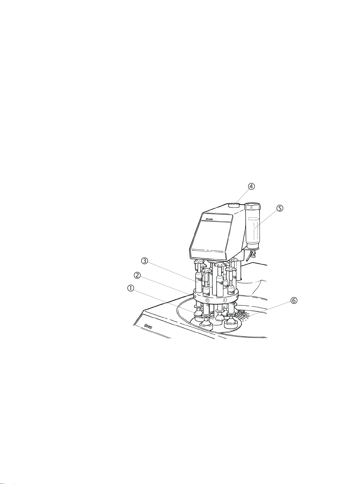
Getting Acquainted with
LaboForce-Mi
LaboForce-Mi mounted on
LaboPol-35 (accessory)
LaboForce-Mi
Instruction Manual
1. Getting Started
In the packing box you should find the following parts:
1 LaboForce-Mi
1 Allen-key 6 mm for securing LaboForce-Mi on LaboPol-35
1 Nylon tube 4 mm dia., 300 mm long
1 Instruction Manual
Take a moment to familiarise yourself with the location and names of
the LaboForce-Mi components.
2
Thrust pad on adjustment column
Release knob
Force adjustment column
Height adjustment screw
Drip lubricator (accessory)
Specimen mover plate

LaboForce-Mi
Setting up LaboForce-Mi
Electrical Connection
Mounting the Drip Lubricator (accessory)
Changing the Lubricator Tube
Instruction Manual
LaboForce-Mi is designed to be mounted on Struers’
grinding/polishing machine LaboPol-35 only.
Please Note
For instructions on how to set up and connect LaboPol-35,
please see the LaboPol-35 Instruction Manual.
Remove the black plastic lid from the pre-punched hole on
LaboPol-35.
Lead the LaboForce-Mi column through the hole, and position
the head of LaboForce-Mi over the turntable of LaboPol-35.
Remove the two light grey caps from the left hand side of
LaboPol-35.
Tighten the two screws with the enclosed allen-key.
Move the handle on the left hand side of LaboForce-Mi up, to
allow the head to move to the uppermost position.
Mount a specimen mover plate on LaboForce-Mi.
Mount a grinding/polishing disc on LaboPol-35.
Press the head down and adjust the distance between
preparation disc and specimen mover plate to about 2 mm by
turning the black knob on top of LaboForce-Mi.
Connect LaboForce-Mi to the female plug on the back of LaboPol-35,
marked specimen mover.
A drip lubricator provides the necessary lubricant during the
preparation process.
Remove the drip lubricator from its box.
Loosen the finger screw underneath LaboForce-Mi.
Guide the bottom plate of the drip lubricator onto the finger screw
and the positioning pin underneath the LaboForce-Mi, and retighten the finger screw.
Hold the lubricant bottle with one hand and remove the lid.
Fill the bottle with lubricant.
Replace the lid and the drip lubricator is ready to use.
To apply the lubricant to exactly the right spot on the preparation
disc, a different length of lubricator tube may be necessary.
300 mm of spare tube is supplied with LaboForce-Mi.
To remove the present tube from the drip lubricator press back the
retaining ring and pull out the tube.
To insert the new tube simply press it into the hole in the retaining
ring.
Use a pair of scissors to cut to the correct length.
3
Mounting the
Specimen Mover Plate
Specimen Mover Plate
Inserting a Specimen
Adjusting the Force
Coarse Adjustment
Fine Adjustment
–
Removing the
LaboForce-Mi
Instruction Manual
2. Operation
Unlock LaboForce-Mi and let it move into top position.
Turn LaboForce-Mi to the left over the edge of LaboPol-35.
Place the specimen mover plate under the column, align the pin
and the slot and press it upwards.
Move LaboForce-Mi back into position, press it down and lock
the handle.
As specimens must fit the holes in the specimen mover plate
quite accurately, the specimen mover plate must be changed
when samples of another size are prepared.
To remove a specimen mover plate, turn the plate clockwise to
release it.
Lift the thrust pad on the adjustment screw to make room for the
specimen.
Place the specimen in one of the holes of the specimen mover
plate and lower the thrust pad.
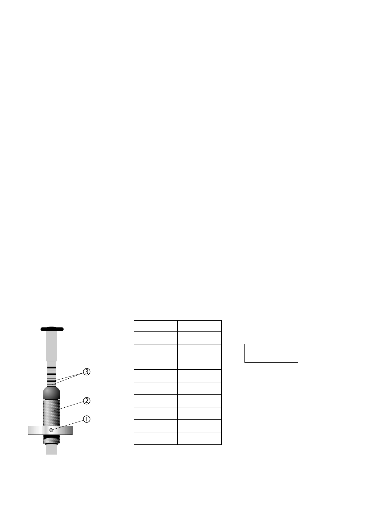
There are two ways to adjust the force.
Press the release knob and move the column up or down
to approximately the correct force.
Adjust the force by turning the column . The marks on the spring
loaded column correspond to the actual force in Newton as stated
below:
Indication Force
4
0
1 —
0 N
2.5 N
—
Thin mark
Black mark
2 –
3 —
4 –
5 —
6 –
7 —
8 –
Make sure that the pressure feet not in use do not touch the
preparation surface. If necessary, press the release button
5 N
7.5 N
10 N
12.5 N
15 N
17.5 N
20 N
WARNING
and move the pressure feet not in use upwards.
 Loading...