

Struers Exotom 100 Instruction Manual

Exotom-100
Instruction Manual
Manual No.: 15047001
Date of Release 30.07.2003


Exotom-100
A
A
Instruction Manual
Table of Contents Page
User’s Guide ..............................................................1
Reference Guide.......................................................19
Quick Reference Card .............................................48
lways state Serial No and Voltage/frequency if you have technical questions or when ordering spare parts. You will
find the Serial No. and Voltage on the type plate of the machine itself. We may also need the Date and Article No of
the manual. This information is found on the front cover.
The following restrictions should be observed, as violation of the restrictions may cause cancellation of Struers legal
obligations:
Instruction Manuals: Struers Instruction Manual may only be used in connection with Struers equipment covered by
the Instruction Manual.
Service Manuals: Struers Service Manual may only be used by a trained technician authorised by Struers. The
Service Manual may only be used in connection with Struers equipment covered by the Service Manual.
Struers assumes no responsibility for errors in the manual text/illustrations. The information in this manual is subject
to changes without notice. The manual may mention accessories or parts not included in the present version of the
equipment.
The contents of this manual is the property of Struers. Reproduction of any part of this manual without the written
permission of Struers is not allowed.
ll rights reserved. © Struers 2003.
Struers A/S
Pederstrupvej 84
DK-2750 Ballerup
Denmark
Telephone +45
Fax +45 44 600 801
44 600 800


Exotom-100
Instruction Manual
Exotom-100
Safety Precaution Sheet
To be read carefully
before use
1. The operator(s) should be fully instructed in the use of the machine and its cut-
off wheels according the Instruction Manual and the instructions on the cut-off
wheels.
2. Use the supplied Allen key to remove the two red transport screws at the rear of
the machine. Do not attempt to open the protection guard before the screws
have been removed.
3. The machine must be placed on a safe and stable support. All safety functions
of the machine must be in working order. The machine must be levelled by
means of the adjustable legs provided.
4. The unit must be installed in compliance with local safety regulations.
5. Prior to lifting the unit by the built-in truck lifting point, ensure that the boom is
properly secured with the locking pins provided. Before transport, secure the
cutting arm with the locking system provided.
6. To achieve maximum safety and lifetime of the machine, use only original
Struers consumables.
7. Use only intact cut-off wheels. The cut-off wheels must be approved for a
spindle speed of min. 1950 rpm / 42 m/s. Do not use sawblades.
8. Observe the current safety regulations for handling, mixing, filling, emptying and
disposal of the additive for cooling fluid.
9. The workpiece must be securely clamped in the quick-clamping device or the
like. Large or sharp workpieces must be handled in a safe way.
10. Struers recommend the use of an exhaust system as the cutting materials may
emit harmful gasses or dust. See the instructions of the cut-off wheel.
11. The machine emits only moderate noise. However, the cutting process itself
may emit noise, depending on the nature of the workpiece. In such cases, use
of hearing protection is recommended.
12. The machine must be disconnected from the mains prior to any service.
13. Ensure that the cut-off wheel is secured before working on or around the cutting
table.
14. Do not put hands through the rubber curtain during operation of the machine.

Exotom-100
Instruction Manual
15. Protruding workpieces should be shielded or marked.
16. Use of working gloves is recommended as workpieces may be both very hot
and produce sharp edges.
17. If any unusual noise is heard when the protection hood is operated, refrain from
further use of the machine, and contact Struers service technician.
The equipment is designed for use with consumables supplied by Struers. If subjected to misuse, improper
installation, alteration, neglect, accident or improper repair, Struers will accept no responsibility for
damage(s) to the user or the equipment.
Dismantling of any part of the equipment, during service or repair, should always be performed by a qualified
technician (electromechanical, electronic, mechanical, pneumatic, etc.).

Exotom-100
Instruction Manual
User’s Guide
Table of Contents Page
1. Getting Started
Checking the Contents of Packing................................................... 3
Recirculation Cooling Unit........................................................ 3
Unpacking and Placing Exotom-100................................................ 3
Mounting the Control Panel............................................................. 4
Getting Acquainted with Exotom-100 ............................................. 5
Side view, left............................................................................. 6
Side view, right.......................................................................... 6
Cooling unit compartment ........................................................7
Power Supply .................................................................................... 8
Mounting the Cut-off wheel .............................................................8
Direction of the Cut-off Wheel .................................................. 8
Connection to an External Exhaust System ...................................8
Setting Up the Recirculation Cooling Unit .....................................9
Direct Water Supply for the Cooling Unit....................................... 9
2.
Operation
Using the Controls.......................................................................... 10
Control Panel of Exotom-100 ..................................................10
Control Panel Functions................................................................. 11
Display Types.................................................................................. 11
Setting the Language .....................................................................12
Reading the Cutting Display.......................................................... 13
Changing Cutting Mode and Cutting Parameters........................ 14
Changing Cutting Mode ..........................................................14
Changing Cutting Parameters................................................ 14
Reading the Motor Information..............................................14
Sleep Mode............................................................................... 14
Changing the Cut-off Wheel........................................................... 15
Clamping the Workpiece ................................................................ 15
Positioning the Cut-off Wheel ........................................................15
QuickPosition.................................................................................. 16
Cutting Parameters........................................................................16
Feed ................................................................................................. 16
Force ................................................................................................16
Stop.................................................................................................. 16
AutoStop................................................................................... 16
1

Exotom-100
Instruction Manual
Setting the Cutting Parameters .................................................... 17
Cutting on Exotom-100................................................................... 17
Starting the Cutting................................................................ 17
Fast advance ............................................................................17
Stopping the Cutting (Manual Stop) ...................................... 17
Re-starting cutting ..................................................................17
Direct Cut........................................................................................ 18
ExciCut............................................................................................ 18
AxioCut (option).............................................................................. 18
Additional cooling ...........................................................................18
2

Checking the Contents of
Packing
Recirculation Cooling Unit
Unpacking and Placing
Exotom-100
Exotom-100
Instruction Manual
1. Getting Started
The packing box contains the following items:
1 Exotom-100
1 Control Panel for Exotom-100
1 Allen key (5 mm) for mounting Control Panel
3 Screws (5 mm)
1 Fork spanner (30 mm) for cut-off wheel
1 Spanner (comb. 12/17 mm) for adjustment of the
Control Panel
1 Drain hose, 2 m
1 Fitting for drain hose
2 Cabinet doors
1 Set of Instruction Manuals
1 Recirculation cooling unit
1 Trolley for cooling unit
Unscrew the nuts from the four transport bolts fixing the machine to
the pallet.
Lift the machine from the pallet by means of a forklift truck from the
front, and place in a suitable location.
Remove the safety-springs from the front crossbar, and remove bar.
Use the supplied Allen key to remove the two red transport
screws at the rear of the machine. Do not attempt to open the
protection hood before the screws have been removed.
Take out the loose parts (trolley, tank, drain hose etc.).
Mount the cabinet doors.
Turn the adjustable feet so that the machine stands firmly and is
level.
NB!
Please remove the transportation
support before use.
3
Exotom-100
Instruction Manual
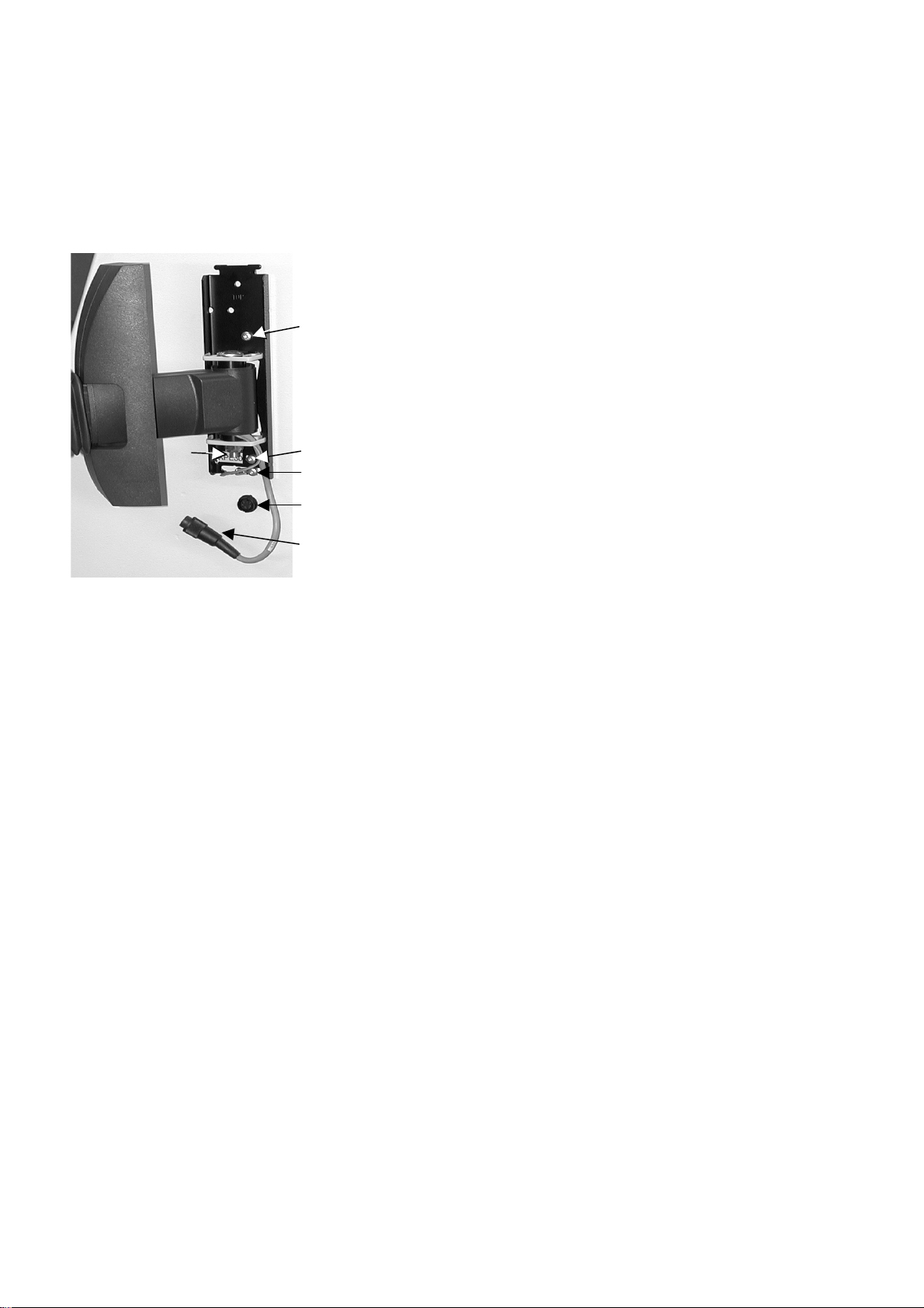
Mounting the Control Panel
Unpack the Control Panel and mount on right side of unit using the
two 5 mm screws and Allen key supplied (use holes
and as
indicated on drawing).
Mount the earth wire below the mounting plate using the
third 5 mm screw
Press cover towards cabinet wall until it snaps onto the mounting
plate.
Connect Control Panel plug to socket .
The position of the Control Panel is controlled by a friction
mounting. After mounting the control panel it is possible to
adjust the mobility of the Control Panel this way:
Adjust the main joint with the nut using the combined
12/17 mm spanner supplied.
The joint just behind the Control Panel may be adjusted too,
using the same spanner.
.
4
Exotom-100
Instruction Manual
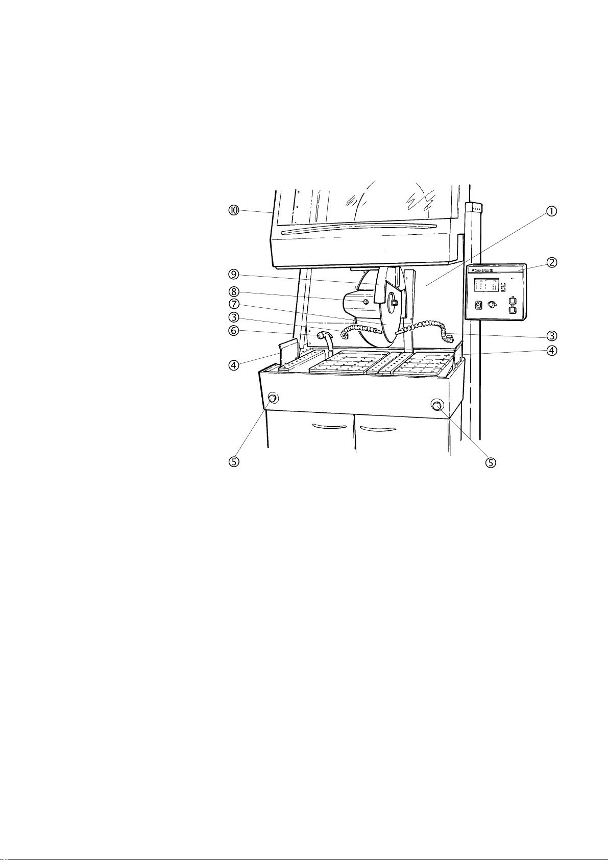
Getting Acquainted with
Exotom-100
Take a moment to familiarise yourself with the location and
names of the Exotom-100 components.
Cutting chamber
Control Panel
Flexible water jets
Protection guards
Emergency stops
Flushing hose with flush nozzle
Cut-off wheel
Spindle lock button
Guard for cut-off wheel
Protection hood
5
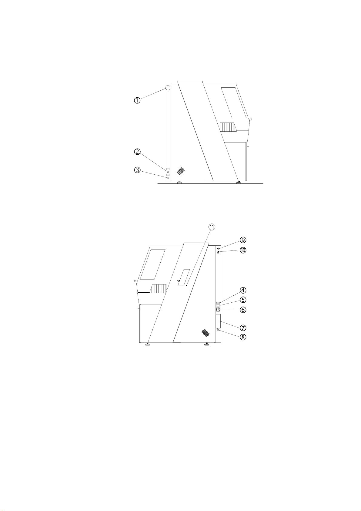
Side view, left
Exotom-100
Instruction Manual
Exhaust flange
Water inlet
Water outlet
Side view, right
Name Plate
Type plate
Main Switch
Electrical connection box
Connection for electrical cable for power supply
Connection for external warning light
Fuse socket for external warning light
1 Connection for Control Panel
6
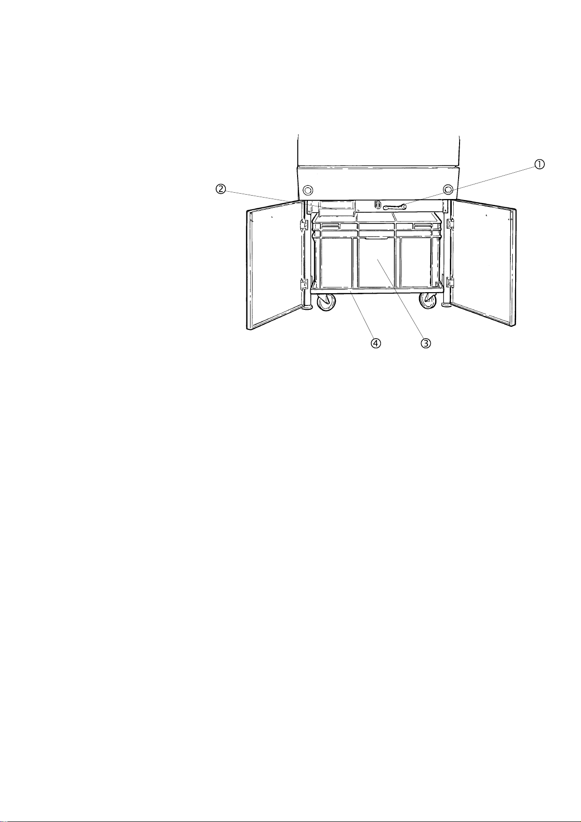
Cooling unit compartment
Exotom-100
Instruction Manual
Cooling unit drain pump on/off
Filter drawer
Recirculation cooling unit
Trolley for cooling unit
7
Exotom-100
Instruction Manual
Power Supply
Mounting the Cut-off wheel
ee
Nut
Flange
Washer
Direction of the Cut-off Wheel
Connection to an External
Exhaust System
Before connecting the machine, check that the mains voltage is
correct by referring to the type plate.
Open the electric connection box and connect a 4-lead cable in the
following way:
PE: earth
L1: phase
L2: phase
L3: phase
IMPORTANT
Check that the mains voltage corresponds to the voltage stated on the type
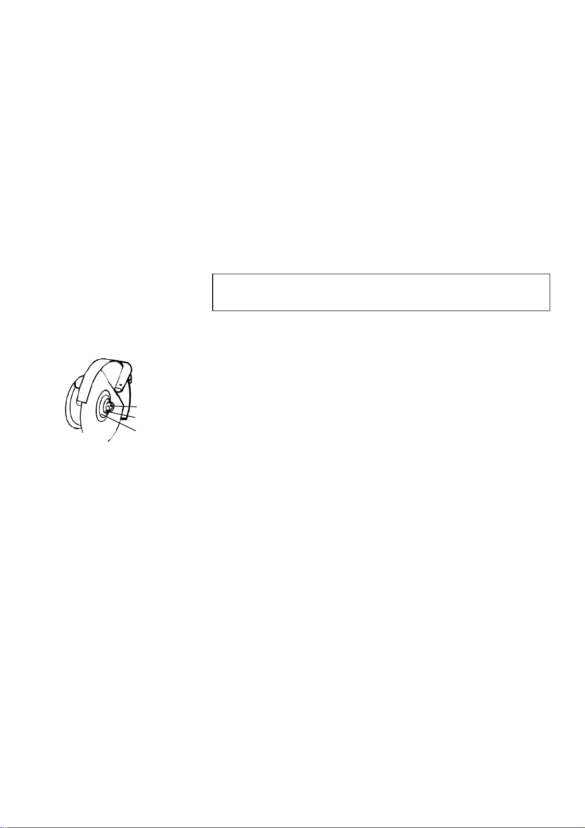
plate on the side of the machine.
Press the knob for the spindle lock on the left-hand side of the cut-off
wheel, while turning the cut-off wheel until the spindle lock clicks.
Remove the nut with a fork spanner (30mm).
Remove the flange and the cut-off wheel.
Mount the new cut-off wheel with a cardboard flange on each side.
Mount the flanges and nut. Tighten carefully.
To check that the cut-off wheel rotates in the direction indicated
on the wheel-guard, do the following:
Close the protection hood.
Turn Main Switch to On.
Press START s.
Check the rotational direction of the wheel.
Press STOP o.
If the direction of rotation is incorrect, turn mains off and switch
two of the phases.
Struers recommends the use of an exhaust system as workpieces
may emit harmful gases when cut. The unit is prepared for
connection to an exhaust system via an 80 mm fitting on the left
hand side of the cabinet.
Recommended capacity for exhaust system: 350m
3
/h at 0mm
water gauge.
8

Exotom-100
Instruction Manual
Setting Up the
Recirculation Cooling Unit
Direct Water Supply for the
Cooling Unit
Check that the nylon sieve in the filter drawer is properly placed and
close the drawer.
Mount the drain hose on the back of the machine.
Place the recirculation cooling unit in the compartment.
IMPORTANT
The cooling unit must be positioned inside the compartment as indicated by
the arrows on the edge of the cooling unit.
Fill the cooling unit with 150 l of water (5-10 cm from the upper
edge).
Use additive enclosed with the machine and add to cooling water as
specified on the bottle label and stir.
Exotom-100 may be directly connected to the water mains.
Connect the water inlet fitting (½” internal, ¾” external thread).
Open the external water supply.
Fill the cooling unit with 150 l of water (5-10 cm from the upper
edge).
Shut off the water.
Add additive in the quantity stated on the bottle label and stir.
IMPORTANT
When the cooling unit is pushed into the compartment, care should be
taken that the flushing hose is not trapped behind it.
To counter this, pull the flushing hose all the way out of its holder, then
replace. The flushing hose, should then rest inside the cooling unit.
9
Using the Controls
Control Panel of Exotom-100
Exotom-100
Instruction Manual
2. Operation
10
Exotom-100
Instruction Manual
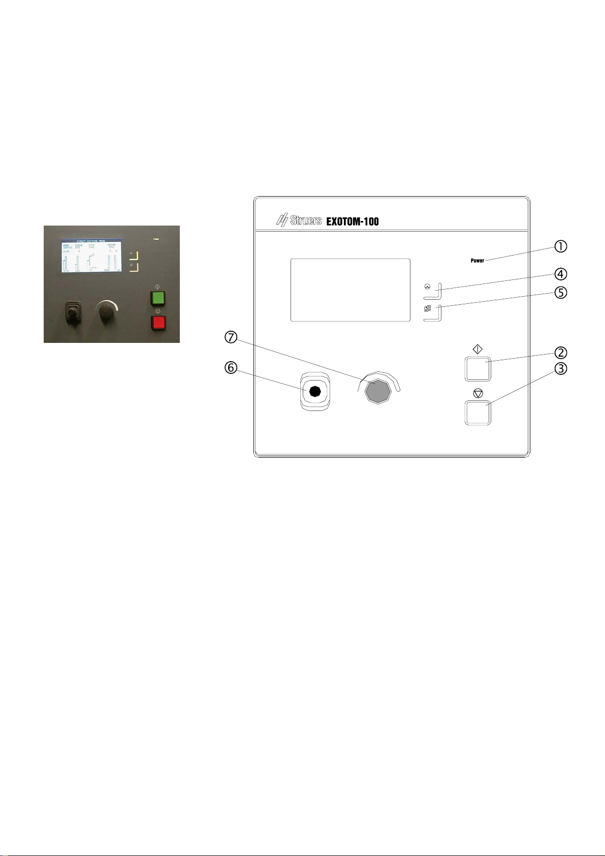
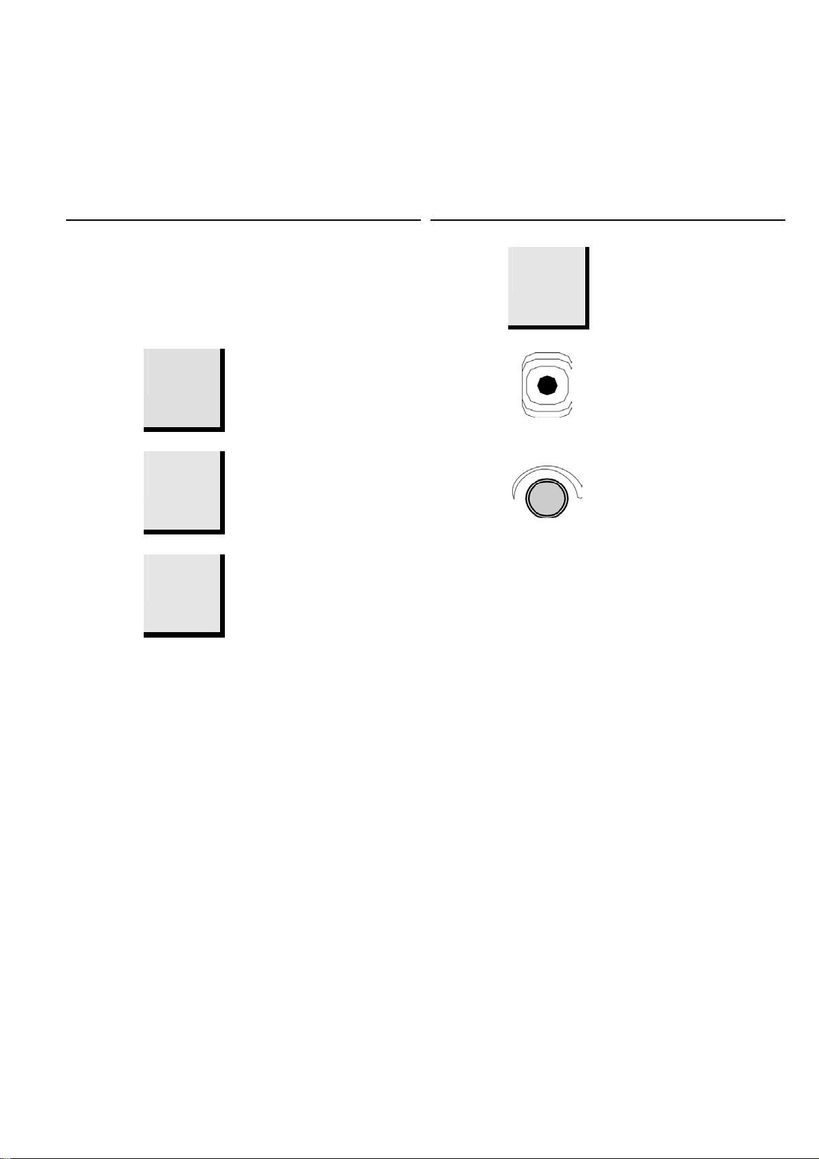
Control Panel Functions
Name Key Function Name Key Function
1
POWER
2
START
3
STOP
4
CUTTING
MODE
Power
s
o
U
Lights when the Main Switch has
been turned to ON.
Starts the machine and recirculation
unit.
Stops the machine and recirculation
unit.
Push button to select desired cutting
mode: Direct cutting, ExciCut,
AxioCut/Step, AxioCut/Sweep.
5
MENU
m
6
JOYSTICK
7
MULTIFUNCTION
KNOB
Push button to toggle between
Cutting menu (daily use) and
Configuration menu (basic settings).
Move up- or downwards to position
cut-off wheel.
Push knob to select function. Turn
knob to adjust settings.
Display Types
The Cutting Display will be shown on the Control Panel when
turning Exotom-100 on. This display is for everyday use.
By pressing the MENU m button once, the CONFIGURATION
menu will appear on the display. This menu will normally only be
accessed during installation.
11

Exotom-100
Instruction Manual
Setting the Language
m
D
D
D
Press MENU m button once to select
CONFIGURATION Menu.
Turn knob to toggle between parameters in the
CONFIGURATION Menu.
Push knob to select LANGUAGE. A pop-up menu
appears.
From the pop-up menu, select your preferred language
by pushing the knob.
Press MENU m button to move from
CONFIGURATION Menu to Cutting Display.
12
Exotom-100
Instruction Manual
Reading the Cutting Display
A
B
Cutting Mode
Cutting Parameters and Motor
Information
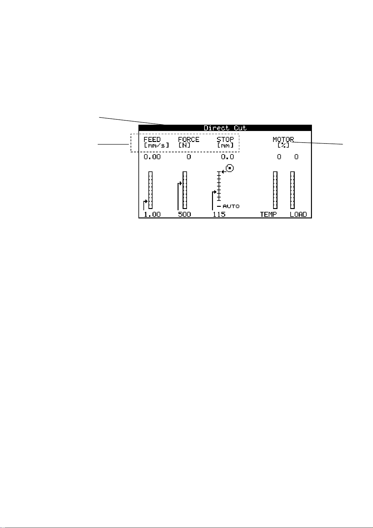
The Cutting Display offers three types of information:
Cutting Mode
Cutting Parameters, and
Motor Information
A Cutting Mode.
B Cutting Parameters.
C Motor Information.
The top bar displays the selected Cutting Mode:
Direct Cutting, ExciCut, AxioCut/Step or AxioCut/Sweep
(AxioCut/Step and -/Sweep are optional).
The large window on the Cutting Display, displays information
about the Cutting Parameters (FEED, FORCE, STOP) as well as
Motor information (TEMP, LOAD).
The Cutting Parameters (FEED, FORCE and STOP) can be set
both prior to and during cutting. The set value is displayed below
the column. Actual value is displayed above the bar graph.
The Motor Information columns TEMP and LOAD, inform about
the condition of the motor during cutting. Read-out in relative
value (%).
C
13

Exotom-100
Instruction Manual
Changing Cutting Mode and
Cutting Parameters
Changing Cutting Mode
Changing Cutting Parameters
Push knob to select Cutting
Parameter.
Turn knob to adjust setting.
Reading the Motor Information
Sleep Mode
Toggle between the four Cutting Modes, by pressing the
CUTTING MODE button. The selected mode, Direct Cutting,
ExciCut, AxioCut/Step or AxioCut/Sweep, appears on the top bar
of the Cutting Display.
Toggle between the three Cutting Parameters by pushing the
knob. The highlighted Cutting Parameter is selected.
A
B
Actual values of the Cutting Parameters FEED, FORCE and
STOP are displayed on top of the columns (A).
The actual position of the cut-off wheel (relative its starting
position) is displayed graphically by the small icon
to the right
of the STOP column.
Turn the knob to change the setting of the selected Cutting
Parameter. The arrow on the left of the column will move to
reflect the new setting (B).
By moving the pointer of the STOP column below the column,
AUTO mode is selected.
The highlighted area of the bar graphs TEMP and LOAD, shows
the status of the cutting motor:
TEMP. Temperature indicator of the cutting motor.
LOAD. Load indicator of the cutting motor.
To increase the lifetime of the display, the backlight is
automatically switched off if Exotom-100 has not been used for 15
min. Push any key on the Control Panel to re-activate the
backlight.
14

Exotom-100
Instruction Manual
Changing the Cut-off Wheel
Clamping the Workpiece
Positioning the Cut-off Wheel
Press the knob for the spindle lock on the left-hand side of the cut-off
wheel, while turning the cut-off wheel until the spindle lock clicks.
Remove the nut with a fork spanner (30 mm).
Remove the flange and the cut-off wheel.
Mount the new cut-off wheel with a cardboard washer on each side.
Mount the flange and nut. Tighten carefully and close the guard.
IMPORTANT
Conventional cut-off wheels based on Al2O3/SiC abrasives should be placed
between two cardboard washers, to protect the cut-off wheel.
For maximum precision with diamond or CBN cut-off wheels, do not use
cardboard washers.
Clamp the workpiece with the clamping device of your choice e.g. a
quick clamping device. Place the workpiece between the clamp and
the back stop.
Push the clamp towards the workpiece, and lock the quick clamping
device with the locking handle.
Ensure that only one of the quick clamping devices is tight, the
other device should only press lightly. Use support tools if the
geometry of the workpiece makes support necessary.
IMPORTANT
When using the AxioCut cutting mode, the cut-off wheel cover may
hit the jaw of the Quick Clamping Device, if same is mounted in the shown
forward position; ie using the cross-directional T-slot closest to the front of
the machine.
To avoid this situation, place the quick-clamping device as far back as
possible, using the front-most T-slot.
Test possible infringement by starting the machine with the cut-off wheel
completely clear of the clamping device.
Should the cut-off wheel hit the clamping device anyway, no danger is
involved. Exotom-100 will stop automatically and display the following
message: "AxioCut motor blocked".
After clamping, test the correct position of the cut on the
workpiece, by lowering the cut-off wheel into position, min. 1 mm
above the workpiece:
Push the joystick on the Control Panel downwards, to lower the cut-
off wheel. The cut-off wheel stops when the joystick is released.
15

Exotom-100
Instruction Manual
QuickPosition
Cutting Parameters
Feed
Force
Stop
AutoStop
Positioning of the cut-off wheel may be done, by simply pushing
the joystick downwards until the cut-off wheel has contact with
the workpiece. The force is automatically reduced on contact,
preventing damage to the cut-off wheel and the workpiece.
After contact with the workpiece, the cut-off wheel is
automatically retracted 2 mm, to be ready for cutting.
The feed speed can be set to values between 0.05-5.00 mm/sec
(0.002-0.2 "/s).
The maximum permitted force between cut-off wheel and
workpiece can be set to values between 20-700 N (4-150 lbs). A
built-in measuring cell constantly computes the force. If the force
limit is reached, the feed speed will automatically be reduced to a
value that allows the force to stay just below the set limit. As soon
as the force drops below the set limit, the speed will be increased
to the original setting.
NOTE
When cutting with a force below 50 N, beware of hysteresis
(actual force applied may differ from selected cutting force).
There are two ways to set the stop position: AutoStop and Fixed
Stop, explained under Advanced Operations.
When the AutoStop function is selected, the machine
automatically stops when the workpiece has been cut through.
For normal cutting, the AutoStop function is recommended.
16

Exotom-100
Instruction Manual
Setting the Cutting Parameters
Cutting on Exotom-100
Starting the Cutting
Fast advance
Stopping the Cutting
(Manual Stop)
Re-starting cutting
The Cutting Parameters, FEED, FORCE and STOP, are set in the
Cutting Menu.
m
If in CONFIGURATION Menu, press MENU m once to
select Cutting Menu.
Push knob to toggle between parameters in the Cutting
Menu.
D
Turn knob to edit the value of the selected parameter.
D
Push knob to move to next parameter.
Position the cut-off wheel.
Close the protection hood.
Press START s. The cut-off wheel starts rotating, the cooling water
starts running and the cut-off wheel will slowly move down into the
workpiece at the pre-set Feed Rate.
After START
s has been pressed, the cut-off wheel may also be
advanced towards the workpiece manually. To advance the cut-off
wheel, push the joystick downwards. The cut-off wheel will
advance towards the workpiece at maximum speed (5mm/s).
Exotom-100 automatically stops cutting when the workpiece is cut
through.
Press STOP o to manually interrupt the cutting process.
The machine can be stopped at any time during operation by
pressing STOP
o.
Having interrupted cutting, the cut-off wheel has been
automatically moved out of the workpiece.
Press START s to resume cutting.
17
Exotom-100
Instruction Manual
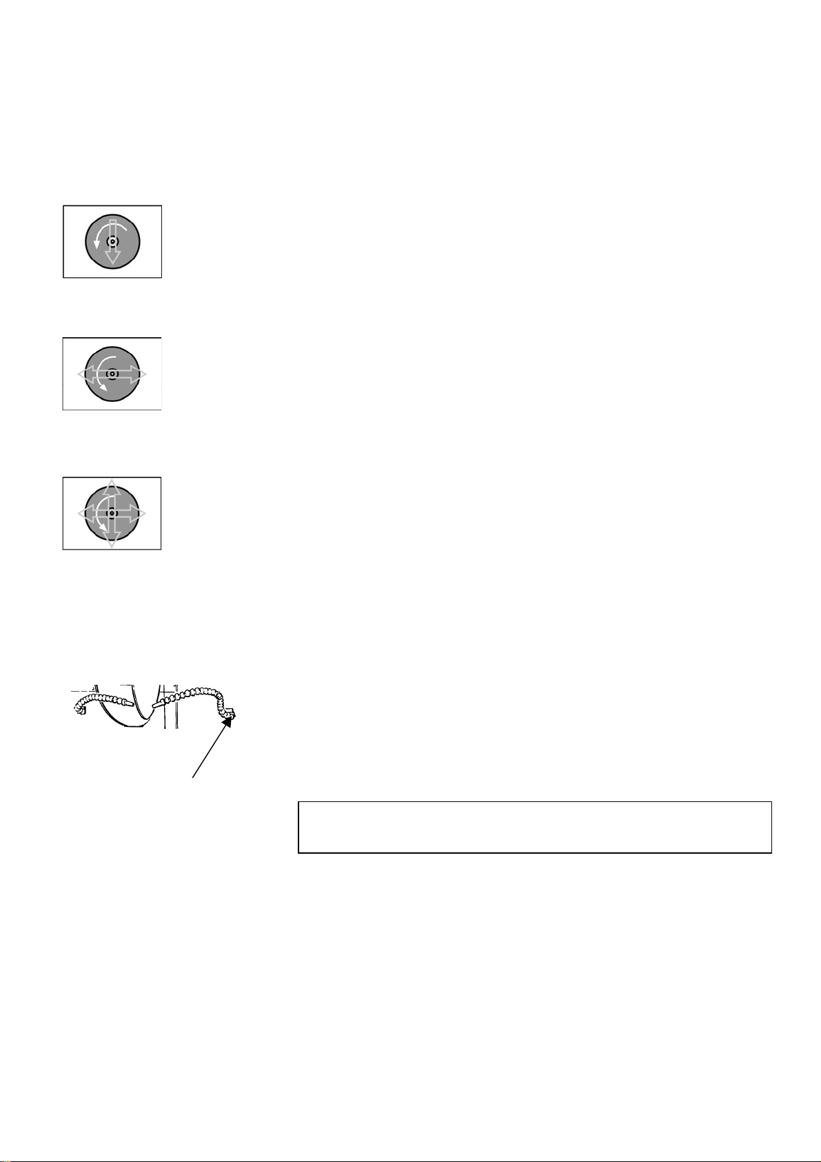
Direct Cut
ExciCut
AxioCut (option)
Additional cooling
To activate jet, turn valve
Direct Cutting is the normal cutting mode. The cut-off wheel is
moved into the workpiece in a slightly curved, vertical movement.
Direct Cutting is intended for ordinary materials.
ExciCut cutting mode is ideal for cutting of very hard materials
(HV >400). The oscillating movement of the cut-off wheel has
three main advantages: less wear on the cut-off wheel, less risk of
damage to workpiece and less risk of motor overheating.
To select ExciCut, press the CUTTING MODE button, until
ExciCut appears in the top bar of the display.
The AxioCut option permits cutting of extra large workpieces
(adding 150mm to max. depth). Two different cutting modes are
provided, Step and Sweep. The Sweep-mode offers better cut-off
wheel economy than the Step-mode. The latter method, however,
is faster.
To select AxioCut/Step or AxioCut/Sweep, press the CUTTING
MODE button, until the desired mode appears in the top bar of
the display.
Two flexible water jets are provided for additional cooling. Cooling
water from the integrated water jets will flow away from the
upper part of the cutting area, particularly when cutting hollow
workpieces. To counter this, use the flexible water jets provided.
Position the cooling jets to the left and right of the cutting area.
Turn the valve on the jet to a position parallel to the hose to activate
the cooling jet. The cooling water will flow as soon as the cutting
starts.
Note
When using the flexible water jets, cooling water is diverted from the
integrated water jets positioned over the cut-off wheel.
18

Exotom-100
Instruction Manual
Reference Guide
Table of Contents Page
1. Advanced Operations
Configuration Menu ....................................................................... 21
Display contrast....................................................................... 22
Language.................................................................................. 22
Return position ........................................................................22
Units......................................................................................... 22
Operation mode .......................................................................22
New Pass Code................................................................................ 23
Changing Operation Mode ............................................................. 24
Cutting Offset .................................................................................25
Cutting Display............................................................................... 26
Cutting Modes................................................................................. 27
Direct Cut........................................................................................ 27
ExciCut............................................................................................ 27
AxioCut (option).............................................................................. 27
AxioCut/Step............................................................................ 28
AxioCut/Sweep......................................................................... 28
Stop Settings................................................................................... 29
AutoStop................................................................................... 29
Fixed Stop ................................................................................ 29
QuickPosition........................................................................... 30
OptiFeed.......................................................................................... 30
Cutting Long Workpieces...............................................................31
Clamping Irregular Workpieces..................................................... 31
Connection to External Exhaust System....................................... 31
Other Safety Features ....................................................................32
Optimising Cutting Results ...........................................................33
2.
Accessories ..........................................................................34
3.
Consumables
Cut-off Wheels................................................................................. 35
Other Consumables ........................................................................ 35
19

Exotom-100
Instruction Manual
4. Trouble-Shooting
Error Messages ............................................................................... 39
Messages ..................................................................................39
Errors ....................................................................................... 39
Fatal Errors .............................................................................39
5.
Maintenance
Daily Service ................................................................................... 42
Cleaning the Cutting Chamber...................................................... 42
Weekly Service................................................................................ 42
Monthly Service ..............................................................................42
Replacing the Cooling Water ..................................................42
Maintenance of Recirculation Unit................................................ 43
Low Level Warning .................................................................43
Refilling the Cooling Unit ....................................................... 43
Emptying the Cooling Unit.....................................................43
Filter Drawer ...........................................................................44
Additive for Cooling Water .....................................................44
Maintenance of Cutting Table .......................................................45
Maintenance of Cut-off Wheels...................................................... 45
Storage of Bakelite Bonded Al2O3 Cut-off Wheels.................. 45
Maintenance of Diamond and CBN Cut-off Wheels ..............45
Maintenance of Clamping Devices................................................. 45
6.
Technical Data......................................................................46
Cutting Capacity...................................................................... 47
20
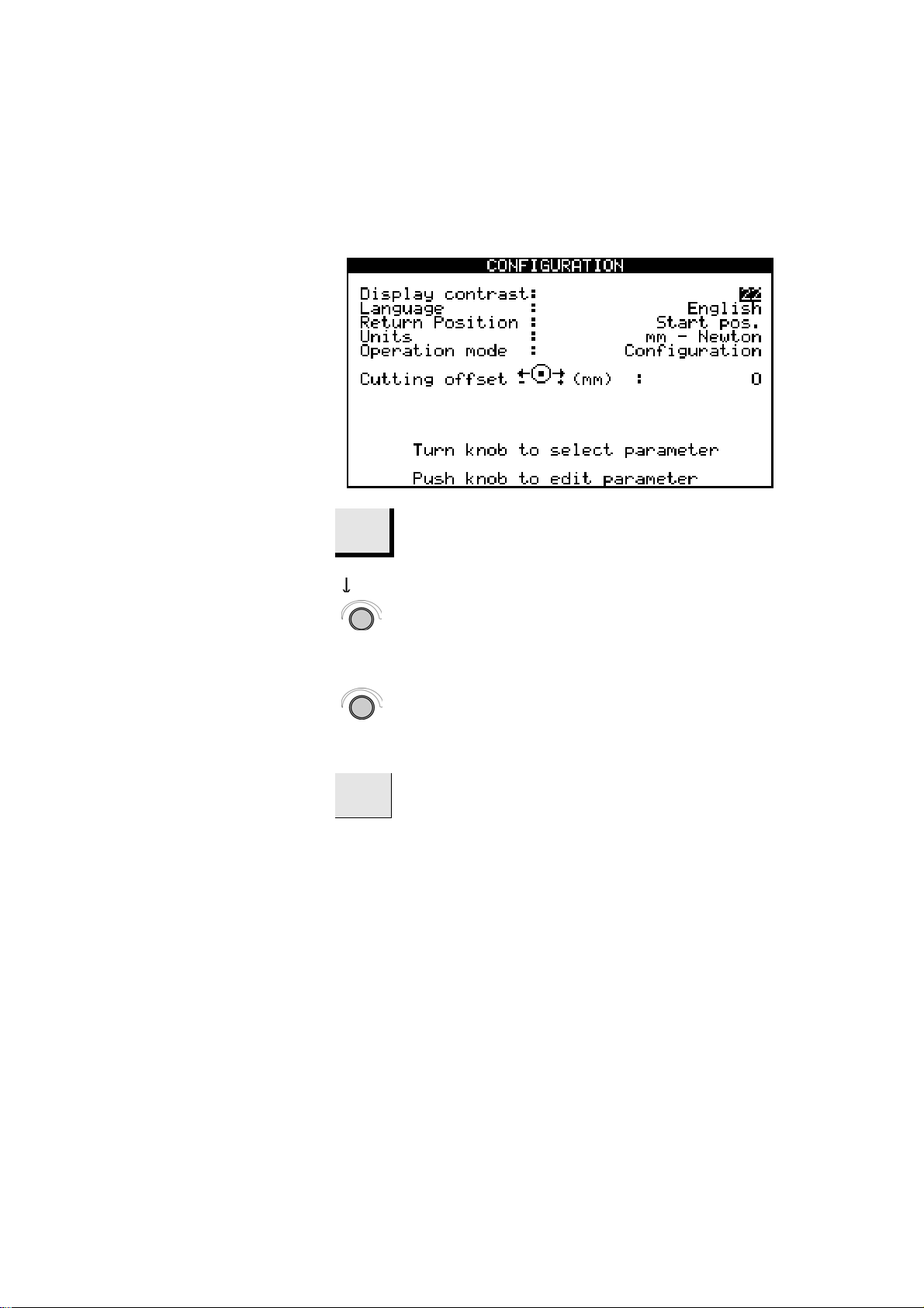
Configuration Menu
Exotom-100
Instruction Manual
1. Advanced Operations
m
Press MENU m button once to select
CONFIGURATION Menu.
D
D
m
Turn knob to highlight different parameters in the
CONFIGURATION Menu.
Push knob to edit the chosen parameter.
Press MENU m button to move from
CONFIGURATION Menu to Cutting Display.
21

Exotom-100
Instruction Manual
Display contrast
Language
Return position
Units
Operation mode
The contrast settings of the display can be adjusted to suit
individual preferences (default value: 22, adjustment interval:
0-50).
The language can be set to English (default), German, French,
Spanish or Japanese.
After cutting or after pressing STOP o, the return movement of
the cut-off wheel can be set to three different functions:
Top: Exotom-100 automatically retracts the cut-off wheel to
the top position.
Start: Exotom-100 automatically retracts the cut-off wheel to
the original position of the cut-off wheel, at the time you
pressed START s (default).
Stay: The cut-off wheel stays down.
Important
Use the Stay function for bakelite bonded diamond or CBN cut-off wheels,
as retraction might destroy the rim of the cut-off wheel.
The Feed, Force and Stop values in the display panel can be set to
displayed in either mm/Newton (default) or inches/pounds force.
It is possible to select three different operation modes:
Configuration: Full functionality
Development: No access to parameters in CONFIGURATION
menu, except Display contrast
Production: Access to START, STOP, Fixed Stop and
movement of cut-off wheel,
and to Display contrast in the
CONFIGURATION menu
To select your own pass code, go to the CONFIGURATION menu.
Select Operation mode to get access to CHANGE OPERATION
MODE menu.
22

Exotom-100
Instruction Manual
New Pass Code
To select your own pass code, go to the CONFIGURATION menu.
Select Operation mode to get access to CHANGE OPERATION
MODE menu.
Push knob to select Pass code
D
Turn knob until default pass code ‘176’ appears.
D
Push knob to select default pass code, and a new line
(New pass code) appears in the CHANGE OPERATION
MODE menu.
D
Turn knob to move the cursor to New Pass Code.
D
D
m
Push knob to select and turn knob to set your own
three-digit pass code.
Press Menu button to confirm your unique pass code
and exit the CHANGE OPERATION MODE menu.
23
Exotom-100
Instruction Manual
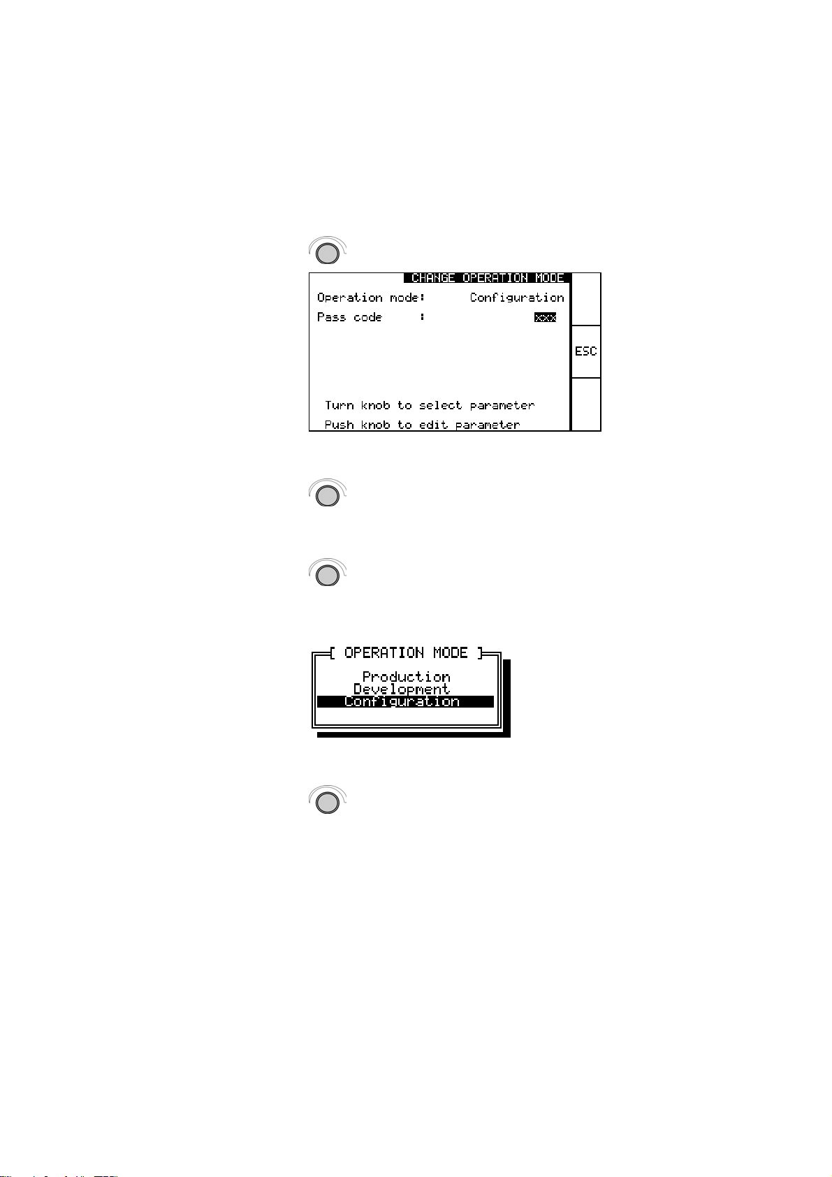
Changing Operation Mode
To change the operation mode, highlight the parameter in the
CONFIGURATION menu.
Push knob to move to Change Operation Mode menu.
D
Enter your unique pass code by turning the knob.
Confirm by pushing knob.
D
Push knob
A pop-up will appear.
D
D
D
Select desired operation mode and push knob to
confirm.
Press Cutting Mode button to move to
CONFIGURATION menu.
24
 Loading...