

Structural Concepts GLDSV3R, GLDSV3R.6094, GLDSV3R.6602, GLDSV4R, GLDSV6R Installation And Operating Manual
...
READ AND SAVE THESE INSTRUCTIONS
INSTALLATION AND
G-SERIES P/N 21-01524
G-SERIES MID-VOLUME REFRIGERATED SERVICE DELI MERCHANDISERS
> VERTICAL FRONT GLASS WITH REAR HINGES
> REMOTE & SELF-CONTAINED > FULL AND OPEN END PANELS
> REFRIGERATED-TO-DRY SWITCH AT CASE REAR (OPTIONAL)
> REAR SLIDING DOORS > OPTIONAL SCALE STAND
GMDSV12R.7183
OPERATING MANUAL
GMDSVC3R
CAUTION!
FRAGILE!
HOLD
GLASS
FIRMLY.
SLOWLY
OPEN &
CLOSE.
CAUTION!
FRAGILE!
DO NOT
STRIKE
DECKS
OR PANS
AGAINST
EDGE OF
GLASS.
GMDSV6R.7115C
Note: See Next Page
For Partial List Of
Models To Which
This Operating
Manual Applies.
Structural Concepts Corporation ∙ 888 E. Porter Road ∙ Muskegon, MI 49441 Phone: 231.798.8888 Fax: 231.798.4960 ∙ www.structuralconcepts.com
Operating Manuals\Standard\G-Series_Mid-Volume Ref Svc Deli_Vertical Glass_Rear Hinges_21-01524.pub
GMDSV4R
GLDSV6R.6670C
GLDSV4R
GMDSV8R
Rev B Date: 1.22.2019
TABLE OF CONTENTS / LIST OF MODELS INCLUDED IN MANUAL
TABLE OF CONTENTS / LIST OF MODELS ENCOMPASSED IN MANUAL ……….………………….…..
OVERVIEW / UNIT TYPE / COMPLIANCE / WARNINGS / PRECAUTIONS / WIRING …..……….……...
INSTALLATION: REMOVAL FROM SKID, REMOVING LOWER FRONT PANELS ..……...…….…….….
INSTALLATION, CONT’D: CASE ADJOINMENT INSTRUCTIONS ……………….………...……………….
INSTALLATION, CONT’D: FRAME SUPPORT RAIL SHIMMING ……………………………………….......
INSTALLATION, CONT’D: FRONT GLASS ALIGNMENT & ADJUSTMENT (VIA RAIL SYSTEM) ……...
INSTALLATION, CONT’D: FIELD WIRING BOX / RACEWAY / LED DRIVER / ANTI-CONDENSATE
AXIAL FANS .…………………………………………..….……………………………………………….
INSTALLATION, CONT’D: REFRIGERATION LINES / STUB-UPS / DRAINS ……..…………….….……..
INSTALLATION, CONT’D: SCALE STAND WITH OUTLETS & CAT5 / FLIP-UP LEDGE ………….……..
START-UP AND OPERATION ………………..………………………………………………………………….
MAINTENANCE FUNDAMENTALS: LED LIGHT FIXTURES / REMOVAL & REPLACEMENT…………...
MAINTENANCE FUNDAMENTALS, CONT’D: SHELF ASSEMBLIES ………………………………....……
MAINTENANCE FUNDAMENTALS, CONT’D: DRAIN, TXV VALVE ACCESS ………………………....….
MAINTENANCE FUNDAMENTALS, CONT’D: REAR SLIDING DOORS ……………………………….…..
MAINTENANCE FUNDAMENTALS, CONT’D: REAR HINGED FRONT GLASS …………………………..
MAINTENANCE FUNDAMENTALS, CONT’D: REFRIGERATED TO DRY SWITCH (OPTIONAL) ……...
MAINTENANCE FUNDAMENTALS, CONT’D: CUTTING BOARD / REAR LEDGE REMOVAL ...……….
MAINTENANCE FUNDAMENTALS, CONT’D: CONDENSATE PACKAGE LAYOUT ……………….…….
CLEANING SCHEDULE - INTERIOR: TO BE PERFORMED BY STORE PERSONNEL .………………...
CLEANING SCHEDULE - EXTERIOR: TO BE PERFORMED BY STORE PERSONNEL ………….……..
CLEANING SCHEDULE -STAINLESS STEEL: TO BE PERFORMED BY STORE PERSONNEL ……...
PREVENTIVE MAINTENANCE - TO BE PERFORMED BY TRAINED SERVICE PROVIDERS ONLY ....
TROUBLESHOOTING - TO BE PERFORMED BY STORE PERSONNEL (UNLESS NOTED
OTHERWISE) ……………………………………………………………………………………………...
TROUBLESHOOTING - CONDENSING SYSTEM (TO BE PERFORMED BY TRAINED SERVICE
PROVIDERS ONLY) ……………………………………………………………………………………...
TROUBLESHOOTING - EVAPORATOR SYSTEM (TO BE PERFORMED BY TRAINED SERVICE
PROVIDERS ONLY) ………………………...……………………………………………………….…...
SERIAL LABEL INFORMATION & LOCATION ..……………………………………...…....…………..….…..
CAREL® TEMPERATURE CONTROLLER INFORMATION ………………………………………….….…..
TECHNICAL SERVICE CONTACT INFORMATION & WARRANTY INFORMATION ...……….…............
2
3-4
5
6
7
8
9
10
11
12
13
14
15
16
17
18
19
20
21
22
23
24
25-27
28
29
30
31-33
34
THIS OPERATING MANUAL INCLUDES (BUT IS NOT LIMITED TO) THE FOLLOWING MODELS:
GLDSV3R
GLDSV3R.6094
GLDSV3R.6602
GLDSV4R
GLDSV6R
GLDSV6RG.5718
GLDSV8R
GLDSV10R
GLDSV8R.7183
GLDSV10R.6094E
GLDSV10R.6670A
GLDSV12R
GLDSV442R.6670F
GLDSV542R.7042B
GLDSV642R.6670C
GLDSV842R.6670B
GLDSV842R.7042D
GLDSV1242R.6670D
GLDSV1242R.6839F
GLDSV1242R.7042F
GLDSV1242R.7186F
GMDSESV8R
GMDSESV12R
GMDSV3D.7215
GMDSV4D
GMDSV4D.7215
GMDSV3R.6694
GMDSV4R
GMDSV4R.6806A
GMDSV4R.6694
GMDSV4R.6749B
GMDSV4R.7215
GMDSV5R.7215
GMDSV6R
GMDSV6R.6694
GMDSV6R.6806C
GMDSV6R.7115C
GMDSV8R
GMDSV8R.6694
2
GMDSV8R.6749A
GMDSV8R.7063B
GMDSV8R.7115D
GMDSV8R.7183
GMDSV8R.7215
GMDSV8R-RD
GMDSV10R.6806E
GMDSV10R.7215
GMDSV12R
GMDSV12R.7063D
GMDSV12R.7115F
GMDSV12R.7215
GMDSV12R.7280
GMDSVC3R.6694
GMDSVC3R.7215
GMDSVC4R
GMDSVC4R.7215
GMGV8.7183
OVERVIEW / UNIT TYPE / COMPLIANCE / WARNINGS / PRECAUTIONS / WIRING - PAGE 1 of 2
OVERVIEW
• These Structural Concepts merchandisers are
designed to merchandise packaged products at 41 °F
(5 °C) or less product temperatures (unless custom
cases with wire rack shelving).
• Product must be pre-chilled to 41 °F (5 °C) or less
prior to being placed in merchandiser.
• Cases should be installed and operated according to
this operating manual’s instructions to ensure proper
performance. Improper use will void warranty.
TYPE
This unit is designed for the display of products in ambient
store conditions where temperatures and humidity are
maintained within a specific range.
• For Type 1 Conditions (most cases): ambient
conditions are to be at 55% maximum humidity and
maximum temperatures of 75 °F (24 °C).
• For Type 2 Conditions: ambient conditions are to be
at 55% maximum humidity and maximum
temperatures of 80 °F (27 °C).
This equipment MUST be installed in compliance with all applicable
ATTENTION
CONTRACTORS
NEC, federal, state and local electrical and plumbing codes.
• If unsure if unit is Type 1 or 2, see tag near serial
label.
COMPLIANCE
• Performance issues when in violation of applicable
NEC, federal, state and local electrical and plumbing
codes are not covered by warranty.
• See below compliance guideline.
WARNINGS
• This page contains important warnings to prevent
injury or death. Please read carefully!
PRECAUTIONS and WIRING DIAGRAMS
• See next page for PRECAUTIONS and WIRING
DIAGRAM information.
POWER CORD AND PLUG MAINTENANCE
(FOR CASES THAT ARE NOT FIELD-WIRED)
• Caution! Risk of electric shock.
• If cord or plug becomes damaged, replace only with
cord and plug of same type. See next page.
COMPLIANCE
WARNING
ELECTRICAL
HAZARD
WARNING
KEEP
HANDS
CLEAR
WARNING
Risk of electric shock. Disconnect power before servicing unit.
CAUTION! More than one source of electrical supply is
employed with units that have separate circuits.
Disconnect ALL ELECTRICAL SOURCES before servicing.
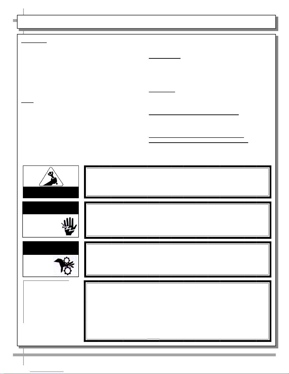
WARNING
Hazardous moving parts. Do not operate unit with covers removed.
Fan blades may be exposed when deck panel is removed.
Disconnect power before removing deck panel.
CAUTION! CHECK BOTH CONDENSATE PAN AND OVERFLOW PAN
Water on floor can cause extensive damage! Before powering up unit:
• Condensate pan MUST BE positioned directly under condensate drain.
• Overflow pan MUST HAVE single plug connected to its box. Units with
optional Clean Sweep™ MUST HAVE two plugs connected.
• WARNING for self-contained units only! Overflow condensate pan
heater rod is hot! Electric condensate pan must be disconnected and
allowed to cool before cleaning or removing from case.
3
OVERVIEW / UNIT TYPE / COMPLIANCE / WARNINGS / PRECAUTIONS / WIRING - PAGE 2 of 2
PRECAUTIONS
• Following are important precautions to prevent
damage to unit or merchandise.
• Please read carefully!
• See previous page for specifics on OVERVIEW,
TYPE, COMPLIANCE and WARNINGS.
CAUTION! LAMP REPLACEMENT GUIDELINES
Fluorescent lamps have been treated to resist breakage and
CAUTION
must be replaced with similarly treated lamps.
LED lamps reflect specific size, shape and overall design.
Any replacements must meet factory specifications.
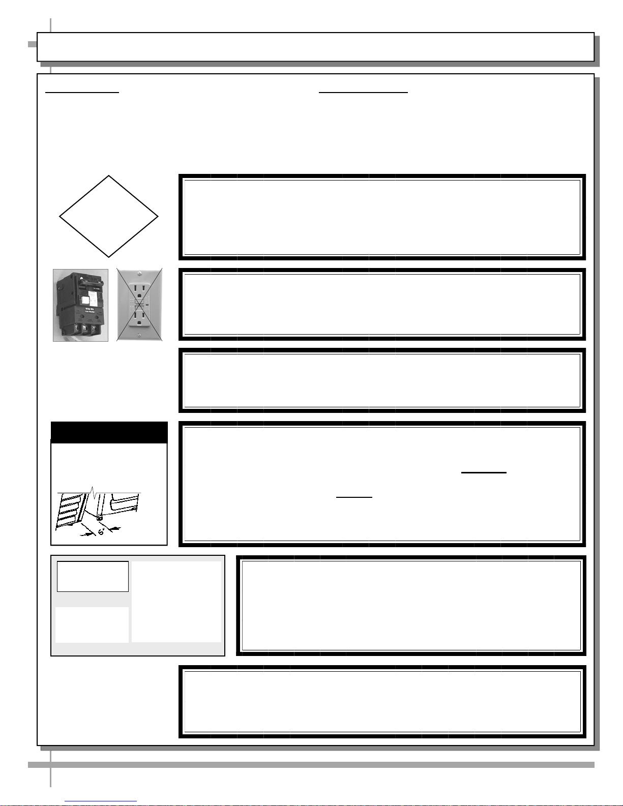
CAUTION! GFCI BREAKER USE REQUIREMENT
If N.E.C. (National Electric Code) or your local code requires
GFCI (Ground Fault Circuit Interrupter) protection,
you MUST use a GFCI breaker in lieu of a GFCI receptacle.
CAUTION! CASES WITH POWER CORD AND PLUG
Risk of electric shock. If cord or plug becomes damaged,
replace only with cord and plug of same type.
WIRING DIAGRAM
• Each case has its own wiring diagram folded and in
its own packet.
• Wiring diagram placement may vary; it may be
placed near ballast box, field wiring box, raceway
cover, or other related location.
CAUTION
CAUTION! ADVERSE CONDITIONS / SPACING ISSUES
• Performance issues caused by adverse conditions are NOT warranted.
• End panels must be tightly joined or kept at least 6-inches away from
any structure to prevent condensation.
• Unit must be kept at least 15-feet from exterior doors, overhead HVAC
vents or any air curtain disruption to maintain proper temperatures.
• Unit must not be exposed to direct sunlight or any heat source.
• Self-Cont. Units: Keep 4” min. air intake / 4” min. air disch. clearance.
CAUTION!
DO NOT RELY ON THERMOMETERS OR THERMOSTATS
FOR ACTUAL PRODUCT (FOOD) TEMPERATURES.
• Thermometers & thermostats reflect air temperatures ONLY.
• For ACTUAL product (food) temperatures, use a calibrated
food thermometer.
WARNING: This product can expose you to chemicals, including
Urethane (Ethyl Carbamate), which are known to the state of
California to cause cancer and birth defects or other reproductive
harm. For more information go to P65Warnings.ca.gov.
4
INSTALLATION: REMOVAL FROM SKID, REMOVING LOWER FRONT PANELS
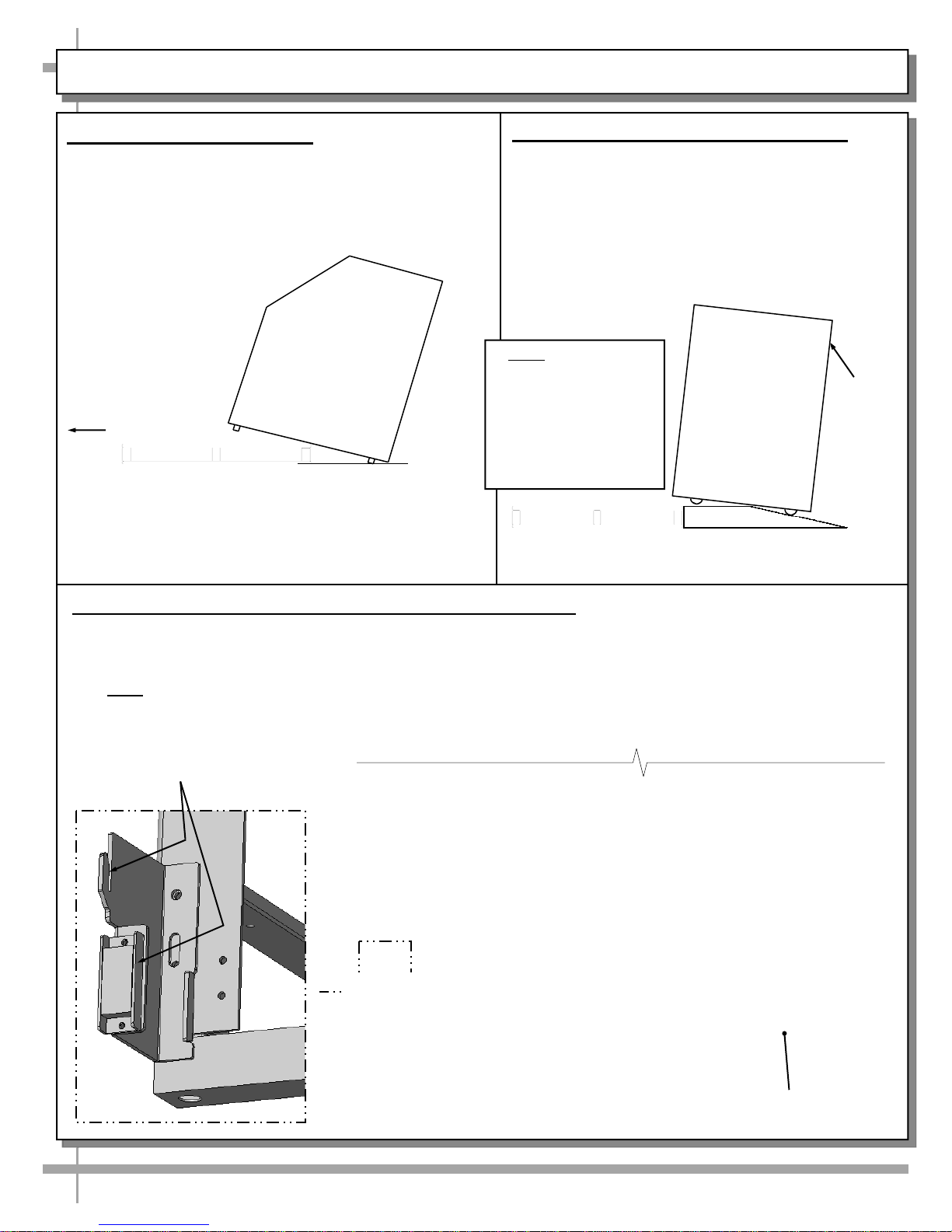
1. Remove Case From Skid
• Remove shipping brace that may be
securing case to skid.
• Support case to prevent tipping.
• Caution! Rails can be damaged if case hits
floor with heavy force!
• Carefully slide unit to
rear of skid and tip
backward off skid.
• Illustration may not
reflect every feature
or option of your
particular case.
Slide Skid Out
Case can be repositioned with pallet truck when
front lower panel is removed. Blocking may be
necessary to obtain adequate height.
2. Remove Case From Skid (Casters)
Remove shipping brackets that may be securing
casters to skid
• Place ramp up against skid (to allow case to
smoothly slide off from skid).
• Maintain support of case at all times or center
of gravity may cause case to fall.
• Unlock Casters. Roll unit to rear of skid.
Roll down ramp
and off from skid.
Note: Illustrations
shown reflect a
general outline of
sample cases and do
not reflect features or
options of your
particular model.
Ramp
Support
while
rolling
case
down
ramp.
3. Removing Vertical Lower Front Panel (and Rear Panel)
• No screw removal is required to remove lower front/rear panel.
• Simply lift panel slots up and off case hooks.
• Replace in same manner it was removed.
• Note: Illustrations below may not exactly reflect every feature or option of your particular case.
Enlarged View of Hook/Magnet
For Retaining Front Panel
Front Panel Shown
Removed and Reversed
5
INSTALLATION, CONT’D: CASE ADJOINMENT INSTRUCTIONS
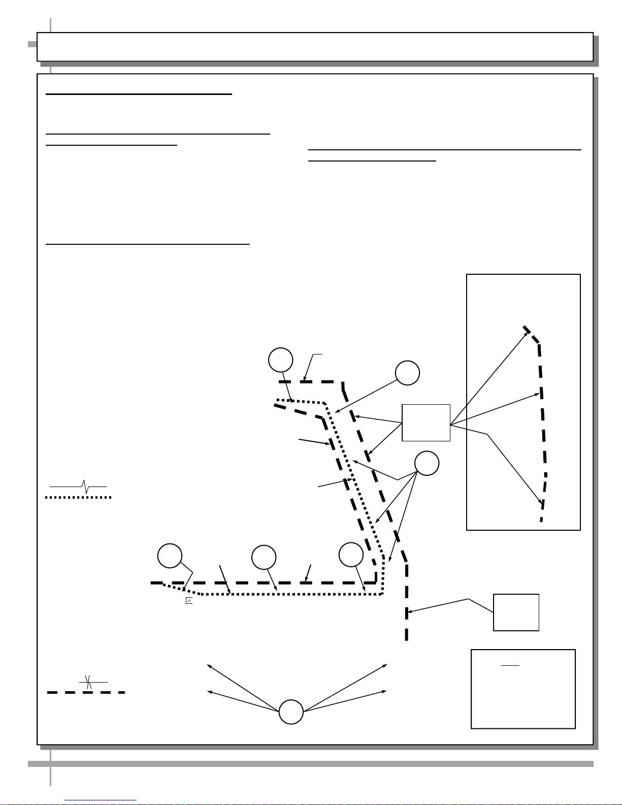
4. Case Adjoinment Instructions
>> Warranty is void if improper caulk/sealant is used.
>> Lay generous beads of caulk/sealant as specified.
A. Prior To Adjoinment - Apply Industrial Butyl
Caulk at Center of Uprights
• Lay a generous bead of industrial grade butyl caulk
at center of uprights (in non-visible areas).
• This butyl caulk prevents refrigerated air from
#4 - Holes are accessible at base frame (through front of
case after front toe-kick has been removed).
• Tighten nuts securely (but do not over-tighten).
• See illustration below.
C. After Adjoinment - Apply Food Grade Silicone Sealant
To Inner And Outer Seams
• After all nuts/bolts are securely attached to case, apply a
escaping between cases (causing condensation and
reducing refrigeration efficiency) as well as
preventing ants or other insects from entering case.
• See illustration below.
• When properly applied, this food grade silicone sealant
B. Adjoining Cases - Using Bolts and Nuts
• Use appropriately sized nuts and bolts for each hole.
#1 - Hole is accessible through rear sliding door
• See illustrations below.
>> You must reattach toe-kick and decking after case
(if you are able to avoid gas cylinder, attach bolt);
otherwise start at #2 in bolt/nut attachment process.
#2 - Holes are accessible through rear sliding door.
#3 - Holes are accessible at underside of decking.
Decking must be removed to attach bolts/nuts.
1
generous bead of food grade silicone sealant at both
inner and outer seams.
will prevent water from seeping between cases (into the
case or to the floor) as well as crumbs or other residue
from entering between case seams.
adjoinment process is
complete.
Outer
Sanitation Bead
2
Industrial Grade
Butyl Calk (For
Refrigeration Bead
Applications)
Food Grade Silicone
Sealant (For Sanitation
Bead Applications)
3
Inner Sanitation
Refrigeration
Bead
Bead
Refrigeration
Bead
Sanitation
3
4
Inner
Bead
3
Outer
Sanitation
Beads
2
Outer Sanitation Bead
To Be Applied At Rear
Adjoinment Seams
(Shown Above)
Outer
Sanitation
Bead
Note: Model
GMDSV8R.7306 Is
Shown at Left. Decking
And Front Toe-Kick
Have Been Removed
For Illustrated
Purposes Only.
6
INSTALLATION, CONT’D: FRAME SUPPORT RAIL SHIMMING
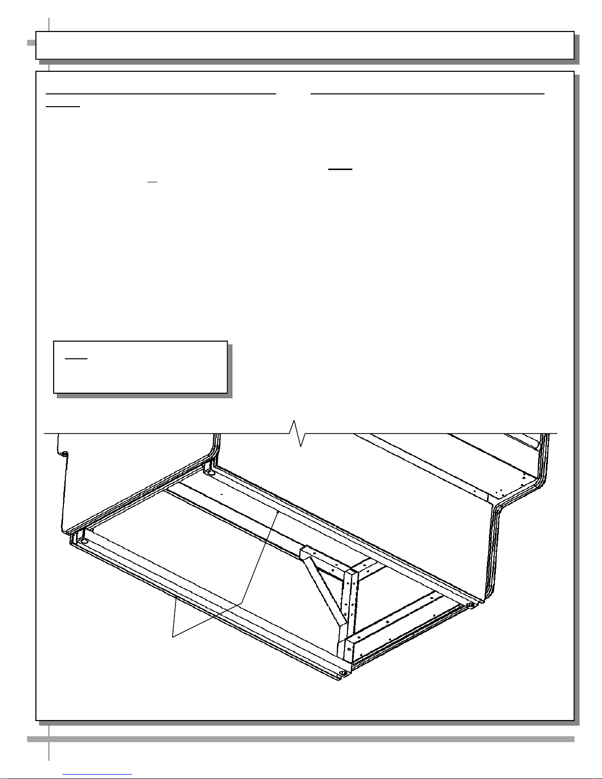
5. Position & Align Case Alongside Other
Cases
• Before adjusting levelers (or shimming frame
support rails), make certain that the case is in
proper position and, if required, aligned with
adjoining case.
• This may require the repositioning of the case
you are installing or the already positioned case.
• Though case below shows both end panels,
case adjoinments routinely consist of end panel
removal for case-to-case placement.
Note: Illustration shown may not
exactly reflect every feature or
option of your particular unit.
6. Frame Support Rails Must Be Shimmed
• Illustration below shows case with frame
support rails.
• Shims will be provided with all cases that have
frame support rails.
• Use shims to level case.
• Note: After case is in position, it must be
sealed to floor to prevent entry or leakage
of liquid or moisture.
Frame Support
Rails
7
INSTALLATION, CONT’D: FRONT GLASS ALIGNMENT & ADJUSTMENT (VIA RAIL SYSTEM)
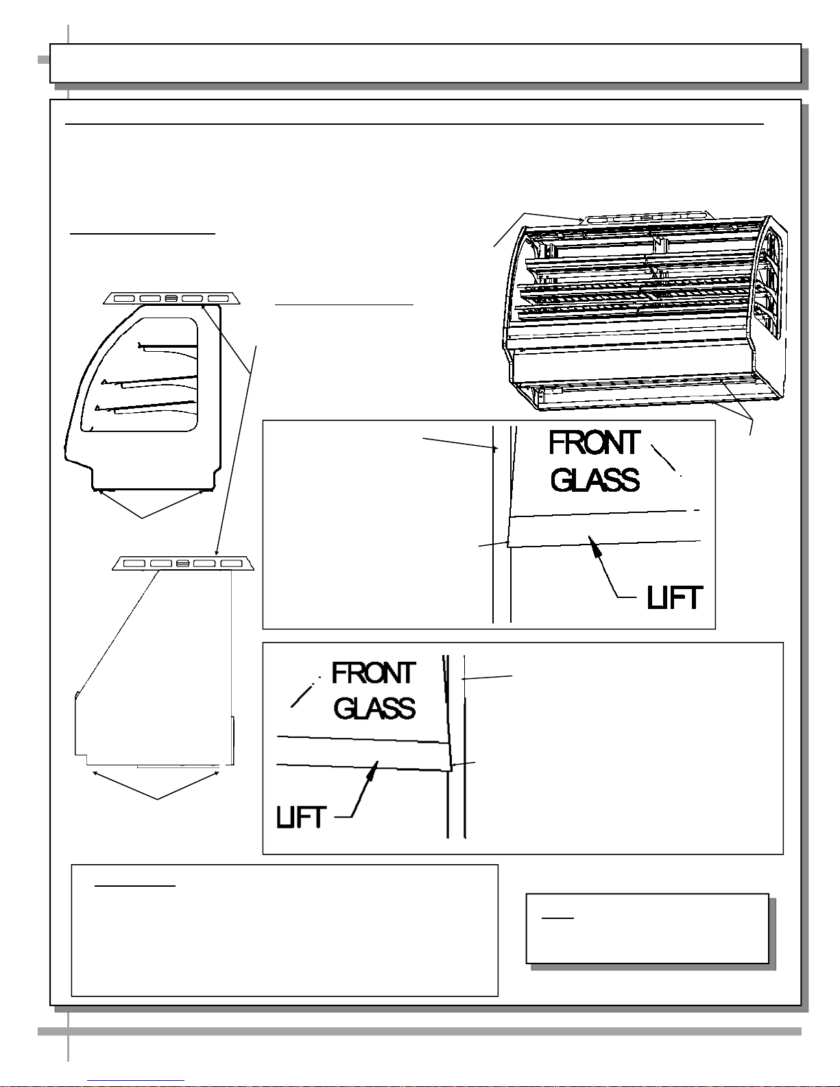
7. Front Glass Alignment & Adjustment via Rail System (For Curved and Flat Front Glass)
• Proper alignment of the front glass is important to create and maintain a seal inside the case.
• Improper alignment can cause air leaks compromising the environment inside the case and create condensation.
• Follow the five steps listed below to assure proper front glass alignment.
• Illustrations shown may not exactly reflect every feature or option of your particular case.
1. Side-to-Side Leveling: Place a level on top of display case (parallel
to front glass). Raise or lower either side of case by inserting shims
under the rails to level the case (following steps 3 and 4 below).
2. Front-to-Back Leveling:
• Place a level on top of case,
perpendicular to the front glass.
• Raise or lower either side of case
by shimming under the rails
(following steps 3 & 4 below).
• Double-check the side-to-side level.
Case with Curved
Front Glass
Rails
Case with Flat
Front Glass
Rails
END PANEL
Rails
3. If FRONT-LEFT CORNER is
too close to end panel (or
hitting it), insert shims at the
BACK LEFT CORNER of case.
END PANEL
4. If FRONT-RIGHT CORNER is too close
to end panel (or hitting it), insert shims at
the BACK RIGHT CORNER of case.
5. Verification:
• After inserting shims, open and shut the front glass.
• Verify (again) that the front glass is properly aligned at
both left-hand and right-hand side of the case.
• If not, repeat the shimming procedure until the front
glass is properly aligned along both sides of the case.
Note: Illustration shown may not
exactly reflect every feature or
option of your particular unit.
8
INSTALLATION, CONT’D: FIELD WIRING BOX / RACEWAY / LED DRIVER / ANTI-CONDENSATE FANS
8. Field Wiring Box / LED Driver / Raceway / LED Driver /
Anti-Condensate Axial Fans
• Probe leads are in probe leads box (on certain models).
Note: Illustration shown may not
exactly reflect every feature or
option of your particular unit.
It is located at customer front-left of case (behind front panel).
• Field wiring box is also located at case front)
• LED driver and terminal strip is also located behind front electrical cover (shown removed for illustrative
purposes).
• Screws hold front electrical cover in place. Unscrew and drop electrical cover down and out.
• Anti-condensate axial fans (for front glass) may be accessed (at underside of front panel) by simply
removing four screws, and dropping fans down.
• Caution! Only certified electricians are to access electrical components!
Light
Ballast
Electrical
Raceway (Typ.)
Terminal
Strip
Anti-Condensate
Axial Fans (Typ.)
Field Wiring Box / LED
Driver (Optional,
Dependent Upon Lighting)
Thermostat
Anti-Condensate
Axial Fans (Typ.)
Thermostat
--- View of Model GMDSV6R.7115C With Front Panel Remove / Electrical Box Cover Transparent ---
9
INSTALLATION, CONT’D: REFRIGERATION LINES / STUB-UPS / DRAINS
9. Refrigration Line Stub-Up Connections
• Refrigerant stub-up access is at underside of
case.
• Stub-up connections are accessed by removing
rear panel (no screws required).
• Run case-to-case connections through cutouts in
base.
• Sweat the high and low pressure connections.
• Fill access hole with suitable filler to insure
watertight integrity of tub.
• Note: Illustration below may not reflect every
feature or option of your particular case.
Note: Model GMDSV6R.7115C (model
shown) may not reflect every feature or
option of your particular unit.
10. Drains
• Cases have drains at left and right hand sides.
• Longer cases may have drain at case center.
• Drain field connection location as shown.
• See next page for illustration of TXV Valve,
Drains, Refrigeration Line Stub-Ups Access, etc.
• Depending upon drain access needs, either front
or rear panel may be removed to gain access to
drain stub-up.
• 1.5” male PVC stub-up connection is under case.
• Drain stub-up may be at case center in extended
length cases.
• Connect tub drain to floor drain. Maintain
1/4” fall per foot to provide proper drainage.
Field Connection
P-Trap
for Drain
Refrigeration Line
Stub-Ups Access
10
INSTALLATION, CONT’D: SCALE STAND WITH OUTLETS & CAT5 / FLIP-UP LEDGE
1. Scale Stand / Ethernet CAT5 / Receptacle
• Optional scale stand location and illustration is
shown below.
• Route the scale stand cord through into
receptacle (shown below).
• Plug scale stand cord into receptacle as shown
in illustration below.
• Depending upon options chosen, CAT5
(Category 5) network cable outlet may also be
available at scale stand base (as shown below).
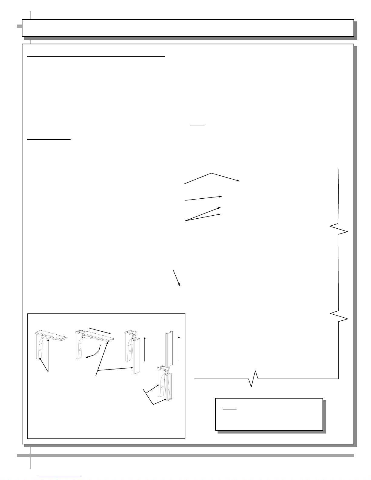
2. Rear Ledge
Rear Ledge is connected to Shelf Track. See below
for Rear Ledge removal steps.
Scale Stand
Ethernet CAT5
110V Electrical Outlets
Rear ledge step-by-step removal method is as follows:
1. Hinged Support Bracket is shown in its standard
upright position.
2 & 3. While upright, Rear Ledge must be
slid away from case and then rotated downward to
vertical position.
3 & 4. From the shelf’s lowered position, lift from
bottom edge upward to disengage shelf track (and
attached Rear Ledge) from bracket.
Note: Illustrations shown may not exactly reflect every
feature or option of your particular case.
-1- -2- -3-
Hinged
Support
Bracket
—— Optional Rear Ledge Removal Steps ——
Note: For clarity, only Shelf Track is shown being
removed. Rear Ledge is attached to Shelf Track.
Shelf
Track
Hinged
Support
Bracket
Sanalite Flip-Down
Ledge
-4-
Note: Illustration shown may not
exactly reflect every feature or
option of your particular unit.
11
 Loading...