


MAGNATRAC
®
RS1000
Operator / Technical Manual
Version 1.01.19
Struck Corp. - Cedarburg, WI 53012
Copyright 2019 C. F. Struck Corp. All rights reserved.
RS1000 Operator Manual 1.01.19.qxp_Layout 1 4/24/19 12:41 PM Page 1
Very Important Facts
& Tips for
Top Performance
The following are random facts that will be expanded on within this Manual. They are brought
to you “first” to impress upon you their primary importance in preventing damage to your RS1000
and also to protect your safety and prevent costly
and unnecessary maintenance expenses.
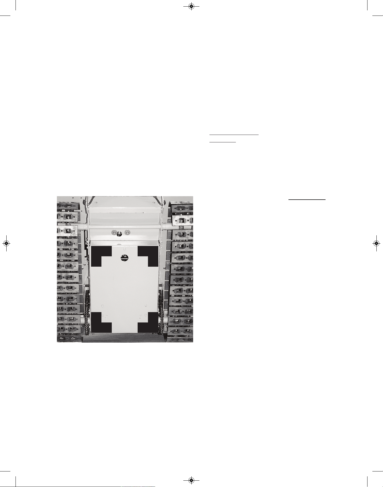
SAFE BLOCKING AREA
When “blocking” your Crawler off the ground for
service, be aware that you should only apply a
hydraulic jack, in the black shaded area
marked below.
ENGINE TORQUE
The greatest amount of power (drawbar torque)
your RS1000 can deliver is near the Engine’s midspeed range. This is marked on your dash area.
To go faster, your Engine’s “drawbar torque” will
be diminished by having to go faster.
Doing all your heavy work at mid-speed does
three things:
1. It keeps the Engine cooler working at a
slower speed.
2
. It gives you maximum drawbar torque.
3. It provides time to make “attachment adjustments” on the go!
You’re encouraged to completely read this Manu
al to get a firm over-view of: how your RS100 operates, significant safety points, and also
maintenance tips on how to increase your MAGNATRAC’S life.
PARKING BRAKE
NEVER FORGET to take off your Parking Brake...
BEFORE you drive away. If you fail to disengage
the Parking Brake, it will wear very rapidly and be
of no value in an emergency!
LUBRICATION OF POWER SHAFT
ENDS
Read and understand the “Special Note” in the
“Belt Installation” section of this manual. By following it ‘s simple lubrication instructions your can
save yourself a lot of work, and potential expense
in the future and make Belt changing much easier.
CLUTCH BELTS
The use of rugged, though uncomplicated Belt
Clutches, gives the RS1000 amazing performance
while at the same time keeps its initial purchase
price and later maintenance costs within the
homeowner’s budget.
The life expectancy of these Clutch Belts is the direct result of the type of work being done and the
operator’s driving technique. It is strongly recommended at this time that you thoroughly read the
Track Clutch Belt Removal & Installation chapter
in the Service Section of this Manual to give you
an over-view of the mechanics of your drive system.
In factory tests of different driving techniques, it
has been found that Belt life will range from 25 to
200 hours. This testing proved that the operator
is the greatest variable in determining Belt life.
From these tests, the following driving rules have
evolved. If followed, they will give you the best
Belt life consistent with the severity of work you
are doing.
2
RS1000 Operator Manual 1.01.19.qxp_Layout 1 4/24/19 12:41 PM Page 2

1
. Do not “ride” your Clutch Controls ...rather op-
erate them smoothly and engage your belts fully.
If your Crawler can not push a particular load you
have two options: immediately reduce the load
(raise the Bucket or Blade) or backup and take a
n
ew angle at the load...never hold your track
controls in a fixed position (forward or rearward)
against an immovable object, you will unneces-
sarily wear the Belts.
2. Your RS1000 has outstanding pushing ability,
but its up to you, the operator, to use its ability in
the most efficient and economical manner.
3. When you want to go slowly for a sustained period, reduce your engine speed...do not “slip” your
Belt Clutches for long periods of time! Your Belt
Clutches are no different than the disk clutch
found in a large truck...if you constantly slip the
Clutch under heavy loads you will burn the clutch
faces and decrease clutch life. It’s no different
with your Belt Clutches.
4. Reserve horsepower has been designed into
your Crawler. This means you can reach the maximum torque necessary to fully drive your RS1000
with your engine operating at only about halfspeed.
TRACKS
The track system of your Magnatrac is the result of
over 50 years of experience.
It is not uncommon in the inital operating hours for
the steel track system to make popping noises
as the intial “wear in” occurs.
The steel track system is of an “unguided” design,
but is extremely stable due to its double track
chain design. A few rules are listed below that if
followed will give you maximum Track performance.
1. Avoid overloading your track system with the
material you are working in. Always work in loose
materials by clearing a “driving path” with the attachment (Blade, Bucket, etc.) you are using. This
technique will allow a minimum amount of material
to enter the track system.
2. Avoid climbing on a pile of loose material and
counter-rotating your tracks. This action will “corkscrew” the Tracks into the pile and force unnec-
e
ssarily large amounts of material into the Tracks.
The steel or rubber track system is designed to
absorb a great deal of material, but the less you
force it to “digest”, the greater will be the Track’s
stability and overall life.
3. Periodically, following the Steel or Rubber Track
Tensioning instructions in your Operator’s/Technical Manual, check your Track tension by checking
the length of the #1806 Spring.
4. Though this Spring adjustment is not a precise
type of adjustment, it must be realized that to overtension the Spring will cause a higher level of wear
in your track bearings, while under-tensioning will
cause potential derailing of your Track.
As always, the Struck Corporation through the
customer service department, stands ready to
help you with any technical or work related questions you may have either now or in the future!
Call (262) 377-3300 or Fax (262) 377- 9247.
3
RS1000 Operator Manual 1.01.19.qxp_Layout 1 4/24/19 12:41 PM Page 3

LIMITED WARRANTY
NEW STRUCK CRAWLERS and/or ATTACHMENTS
(Effective with shipments made after August 1st, 2017)
A. GENERAL PROVISIONS
C.F. Struck Corp. will repair or replace, at its option, for the original purchaser of a new Struck Crawler and/or Attachment, any covered part or parts found upon examination at our factory in Cedarburg, Wisconsin, to be defective in material or workmanship or both; this is the exclusive remedy. Warranty service must be performed by the C. F. Struck Corp. at
their factory in Cedarburg, Wisconsin 53012. Warranty service will be performed without charge for parts or labor. The
purchaser will be responsible, however, for transportation charges to and from the factory.
B
. WHAT IS WARRANTED
A
ll parts of any new Struck Crawler and/or Attachment are warranted for two (2) years, with the following exceptions: Belts,
which are warranted for 90 days (excludes normal wear and tear); Engines, which are warranted by their manufacturer;
and Batteries, which are provided on a complimentary basis and carry no warranty whatsoever. C. F. Struck Corp. reserves the right to make product design and specification changes without notice and without obligation on their part to
present product owners. The Warranty term begins on the date the product is shipped to the purchaser.
C. WHAT IS NOT WARRANTED
(1) Used Products; (2) Any product that has been altered or modified in ways not approved by C. F. Struck Corp.; (3) Depreciation or damage caused by normal wear, lack of reasonable and proper maintenance, failure to follow the product’s
Operator’s/Technical Manual instructions, failure to upgrade crawler with parts furnished at no charge, misuse, lack of
proper protection during storage, or accident (4) Normal maintenance parts and service; (5) Use of Struck Crawler and/or
Attachments in certain industrial-type applications may affect Warranty coverage.
D. RETURNS AND REFUNDS
In the event of defective materials or workmanship the purchaser agrees to allow C.F. Struck Corp the opportunity to correct the defect in a timely manner at the expense of C.F. Struck Corp. It is at the discretion of C.F. Struck Corp to either
correct the defect or refund the purchaser.
To return a Struck Crawler and/or attachment for reasons other than defect the purchaser will be financially responsible
for an 8% restocking fee, and for shipping the Struck Crawler and/or Attachment to the C.F Struck Corp. factory in Cedarburg, Wisconsin 53012. No Returns after 90 days.
E. SECURING WARRANTY SERVICE
To secure Warranty service, the purchaser must:
(1) Report the product defect to the factory in Cedarburg, Wisconsin 1-262-377-3300 or 1-877-828-8323.
(2) Make the part available to the factory in a reasonable period of time.
F. LIMITATION OF IMPLIED WARRANTIES AND OTHER REMEDIES
To the extent permitted by law, neither C. F. Struck Corp. nor any company affiliated with it makes any Warranties, representations or promises as to the quality, performance or freedom from defect of the products covered by this Warranty.
IMPLIED WARRANTIES OF MERCHANTABILITY AND FITNESS FOR A PARTICULAR PURPOSE, TO THE EXTENT APPLICABLE, SHALL BE LIMITED IN DURATION TO THE APPLICABLE PERIOD OF WARRANTY SET FORTH ON THIS PAGE. THE
PURCHASER’S ONLY REMEDIES IN CONNECTION WITH BREACH OR PERFORMANCE OF ANY WARRANTY ON C. F.
STRUCK CORP. PRODUCTS ARE THOSE SET FORTH ON THIS PAGE. IN NO EVENT WILL C. F. STRUCK CORP. OR ANY
COMPANY AFFILIATED WITH IT BE LIABLE FOR INCIDENTAL OR CONSEQUENTIAL DAMAGES.
(Note: Some states do not allow limitations on how long an implied Warranty lasts or the exclusion or limitation of incidental
or consequential damages so the above limitations and exclusions may not apply to you.) This Warranty gives you specific
legal rights, and you may also have other rights which vary from state to state.
G. ASSEMBLY RESPONSIBILITY
Though the MAGNATRAC RS1000, MH4900 and MH8500 are offered completely assembled, it’s still the customer’s re-
sponsibility to provide competent service ability! The servicing can be provided either by the mechanically customer, or by a
local mechanic. All Attachments and accessories are shipped in easy-to-assemble “semi-kit” form for lowest cost shipping. We
provide Manuals and Illustrations for complete service and repair so that anyone with reasonable mechanical skill can preform
all required service work. Check the MAGNATRAC Specifications & Ratings (in Spec Book or Buyer’s Guide) for a list of all
standard features.
I hereby accept the terms and conditions of Warranty described above:
RS1000
MH4900
MH8500
Warranty 9.18
signature
print name
date
4
RS1000 Operator Manual 1.01.19.qxp_Layout 1 4/24/19 12:41 PM Page 4

TABLE OF CONTENTS
VERY IMPORTANT FACTS & TIPS FOR PERFORMANCE . . . . . . . . . . . . . . . . . . . . . . . . . . . . . . . . . . . . .2
1- TO THE OPERATOR . . . . . . . . . . . . . . . . . . . . . . . . . . . . . . . . . . . . . . . . . . . . . . . . . . . . . . . . . . . . . . . . .6
Recognize Safety Information . . . . . . . . . . . . . . . . . . . . . . . . . . . . . . . . . . . . . . . . . . . . . . . . . .6
Understand Signal Words . . . . . . . . . . . . . . . . . . . . . . . . . . . . . . . . . . . . . . . . . . . . . . . . . . . . .6
Follow Safety Instructions . . . . . . . . . . . . . . . . . . . . . . . . . . . . . . . . . . . . . . . . . . . . . . . . . . . . .6
Service Records . . . . . . . . . . . . . . . . . . . . . . . . . . . . . . . . . . . . . . . . . . . . . . . . . . . . . . . . . . . .7
2- SAFETY RULES . . . . . . . . . . . . . . . . . . . . . . . . . . . . . . . . . . . . . . . . . . . . . . . . . . . . . . . . . . . . . . . . . . . .8
Safety Before Starting or Operating . . . . . . . . . . . . . . . . . . . . . . . . . . . . . . . . . . . . . . . . . . . . .8
Operation Safety . . . . . . . . . . . . . . . . . . . . . . . . . . . . . . . . . . . . . . . . . . . . . . . . . . . . . . . . . . . .8
Service Safety . . . . . . . . . . . . . . . . . . . . . . . . . . . . . . . . . . . . . . . . . . . . . . . . . . . . . . . . . . . . . .9
Fire Prevention Maintenance . . . . . . . . . . . . . . . . . . . . . . . . . . . . . . . . . . . . . . . . . . . . . . . . . .9
Protection From Noise . . . . . . . . . . . . . . . . . . . . . . . . . . . . . . . . . . . . . . . . . . . . . . . . . . . . . . .10
Start Engine From Operator Seat Only . . . . . . . . . . . . . . . . . . . . . . . . . . . . . . . . . . . . . . . . . . .10
3- CONTROLS AND INSTRUMENTS . . . . . . . . . . . . . . . . . . . . . . . . . . . . . . . . . . . . . . . . . . . . . . . . . . . . . .11
Left & Right Clutch Controls . . . . . . . . . . . . . . . . . . . . . . . . . . . . . . . . . . . . . . . . . . . . . . . . . . .12
Dashboard Controls . . . . . . . . . . . . . . . . . . . . . . . . . . . . . . . . . . . . . . . . . . . . . . . . . . . . . . . . .13
4- OPERATION . . . . . . . . . . . . . . . . . . . . . . . . . . . . . . . . . . . . . . . . . . . . . . . . . . . . . . . . . . . . . . . . . . . . . . .15
Pre-Starting Inspection . . . . . . . . . . . . . . . . . . . . . . . . . . . . . . . . . . . . . . . . . . . . . . . . . . . . . . .15
Prepare For Engine Starting . . . . . . . . . . . . . . . . . . . . . . . . . . . . . . . . . . . . . . . . . . . . . . . . . . .15
Starting the Engine . . . . . . . . . . . . . . . . . . . . . . . . . . . . . . . . . . . . . . . . . . . . . . . . . . . . . . . . . .15
Warm-up Period . . . . . . . . . . . . . . . . . . . . . . . . . . . . . . . . . . . . . . . . . . . . . . . . . . . . . . . . . . . .16
Traveling . . . . . . . . . . . . . . . . . . . . . . . . . . . . . . . . . . . . . . . . . . . . . . . . . . . . . . . . . . . . . . . . . .16
Parking & Storage . . . . . . . . . . . . . . . . . . . . . . . . . . . . . . . . . . . . . . . . . . . . . . . . . . . . . . . . . . .17
5- FUELS AND LUBRICANTS . . . . . . . . . . . . . . . . . . . . . . . . . . . . . . . . . . . . . . . . . . . . . . . . . . . . . . . . . . . .18
6- LUBRICATION AND PERIODIC SERVICE . . . . . . . . . . . . . . . . . . . . . . . . . . . . . . . . . . . . . . . . . . . . . . . .19
Lubrication and Service Intervals & Periodic Servce Chart . . . . . . . . . . . . . . . . . . . . . . . . . . .19
7- SERVICE . . . . . . . . . . . . . . . . . . . . . . . . . . . . . . . . . . . . . . . . . . . . . . . . . . . . . . . . . . . . . . . . . . . . . . . . .21
Engine & Starter . . . . . . . . . . . . . . . . . . . . . . . . . . . . . . . . . . . . . . . . . . . . . . . . . . . . . . . . . . . .21
Battery . . . . . . . . . . . . . . . . . . . . . . . . . . . . . . . . . . . . . . . . . . . . . . . . . . . . . . . . . . . . . . . . . . . .21
Safety Interlock Switches . . . . . . . . . . . . . . . . . . . . . . . . . . . . . . . . . . . . . . . . . . . . . . . . . . . . .22
Seat & Rear Cover Assembly . . . . . . . . . . . . . . . . . . . . . . . . . . . . . . . . . . . . . . . . . . . . . . . . . .23
Rear Drive Chain Tensioning . . . . . . . . . . . . . . . . . . . . . . . . . . . . . . . . . . . . . . . . . . . . . . . . . .25
Parking/Emergency Brake Adjustment . . . . . . . . . . . . . . . . . . . . . . . . . . . . . . . . . . . . . . . . . . .26
Track Clutch Belts (Removal & Install) . . . . . . . . . . . . . . . . . . . . . . . . . . . . . . . . . . . . . . . . . . .27
Engine Drive Chain (If equipped) . . . . . . . . . . . . . . . . . . . . . . . . . . . . . . . . . . . . . . . . . . . . . . .35
Eninge Drive Micro V-Belt (If equipped) . . . . . . . . . . . . . . . . . . . . . . . . . . . . . . . . . . . . . . . . . .36
Steel Track Removal (If equipped) . . . . . . . . . . . . . . . . . . . . . . . . . . . . . . . . . . . . . . . . . . . . . .39
Steel Track Tensioning (If equipped) . . . . . . . . . . . . . . . . . . . . . . . . . . . . . . . . . . . . . . . . . . . .41
Rubber Track Removal (If equipped) . . . . . . . . . . . . . . . . . . . . . . . . . . . . . . . . . . . . . . . . . . . .43
Rubber Track Tensioning (If equipped) . . . . . . . . . . . . . . . . . . . . . . . . . . . . . . . . . . . . . . . . . .45
8- TROUBLE SHOOTING . . . . . . . . . . . . . . . . . . . . . . . . . . . . . . . . . . . . . . . . . . . . . . . . . . . . . . . . . . . . . . .48
9- SAFETY & WORK PROCEDURES . . . . . . . . . . . . . . . . . . . . . . . . . . . . . . . . . . . . . . . . . . . . . . . . . . . . . .50
Loader Operation . . . . . . . . . . . . . . . . . . . . . . . . . . . . . . . . . . . . . . . . . . . . . . . . . . . . . . . . . . .55
Bulldozing . . . . . . . . . . . . . . . . . . . . . . . . . . . . . . . . . . . . . . . . . . . . . . . . . . . . . . . . . . . . . . . . .59
Backhoe Operation . . . . . . . . . . . . . . . . . . . . . . . . . . . . . . . . . . . . . . . . . . . . . . . . . . . . . . . . . .63
Misc. (Snowplowing, logging, etc.) . . . . . . . . . . . . . . . . . . . . . . . . . . . . . . . . . . . . . . . . . . . . . .68
10- PARTS LISTING & DIAGRAMS . . . . . . . . . . . . . . . . . . . . . . . . . . . . . . . . . . . . . . . . . . . . . . . . . . . . . . .71
Index of Parts . . . . . . . . . . . . . . . . . . . . . . . . . . . . . . . . . . . . . . . . . . . . . . . . . . . . . . . . . . . . . .71
Wiring Diagram . . . . . . . . . . . . . . . . . . . . . . . . . . . . . . . . . . . . . . . . . . . . . . . . . . . . . . . . . . . . .76
IMPORTANT: Though the MAGNATRAC is offered completely assembled, it’s still the customer’s responsibility
to provide competent service ability! The servicing can be provided either by the mechanically-inclined customer, or by a local mechanic. We provide manuals & drawings for complete service and repair so that anyone
with reasonable mechanical skill can perform all required service work.
5
RS1000 Operator Manual 1.01.19.qxp_Layout 1 4/24/19 12:41 PM Page 5
Congratulations…
on your purchase of a quality-built, American
made compact Crawler. We are confident that the
d
ependability and economical performance of
your Magnatrac will prove that you made a wise
choice.
The purpose of this Manual is to acquaint you with
the RS1000 Magnatrac Crawler. This Manual explains how to operate and service your Crawler,
and how to maintain its high operating efficiency.
Instructions are given clearly, with the intention of
making these operations as easy as possible.
Keep this Manual in a convenient place for quick
and easy reference. Use it as a guide whenever
questions arise. You have purchased a dependable, sturdy Crawler, but only by operating and
caring for it properly can you expect to receive the
service and long life for which it was designed.
If in the future you need new parts to replace
those that may be worn, insist on genuine Struck
parts. They are exact duplicates of the originals,
made from the same patterns and of the same
high-quality materials.
When ordering parts, always be sure to give the
following information for your Crawler:
MAGNATRAC Records
MAGNATRAC Model: _ _ _ _ _ _ _ _ _ _ _ _ _ _ _ _ _ _ _ _ _ _ _
MAGNATRAC Serial # _ _ _ _ _ _ _ _ _ _ _ _ _ _ _ _ _ _ _ _ _ _
Engine Model: _ _ _ _ _ _ _ _ _ _ _ _ _ _ _ _ _ _ _ _ _ _ _ _ _ _ _ _ _ _
Engine Serial # _ _ _ _ _ _ _ _ _ _ _ _ _ _ _ _ _ _ _ _ _ _ _ _ _ _ _ _ _
Ship Date: _ _ _ _ _ _ _ _ _ _ _ _ _ _ _ _ _ _ _ _ _ _ _ _ _ _ _ _ _ _ _ _ _ _
Mail: STRUCK CORPORATION
W51N545 STRUCK LANE
CEDARBURG, WI 53012
Phone*: (262) 377-3300 local
(877) 828-8323 toll-free
Fax: (262) 377-9247
email: techsupport@struckcorp.com
Web: www.struckcorp.com
*
For immediate service always call the factory
and ask for a technician.
1- TO THE OPERATOR
RECOGNIZE
SAFETY
INFORMATION
This is the safety-alert symbol. When
you see this symbol on your Crawler or
in this Manual, be alert to the potential
for personal injury.
UNDERSTAND SIGNAL WORDS
A signal word — DANGER, WARNING, or CAUTION — is used with the safety-alert symbol.
DANGER identifies the most serious hazards.
Safety labels with the signal word DANGER or
WARNING are typically near specific hazards.
General precautions are listed on CAUTION
safety labels. CAUTION also calls attention to
safety messages in this Manual.
FOLLOW SAFETY INSTRUCTIONS
Carefully read all safety messages in this Manual
and on your Crawler and Attachment safety labels.
Follow recommended precautions and safe operating practices.
Keep safety labels in good condition. Replace
missing or damaged safety labels.
To keep your Crawler running efficiently, read the
instructions in this Manual.
Left side, right side, front, and rear are viewed by
facing in the direction of the Crawler’s forward
travel.
Record your Crawler serial numbers in the space
provided. You need this information when you
order parts.
6
RS1000 Operator Manual 1.01.19.qxp_Layout 1 4/24/19 12:41 PM Page 6

Date Service Work
_ _ _ _ _ _ _ _ _ _ _ _ _ _ _ _ _ _ _ _ _ _ _ _ _ _ _ _ _ _ _ _ _ _ _ _ _ _ _ _ _ _ _ _ _ _ _
_ _ _ _ _ _ _ _ _ _ _ _ _ _ _ _ _ _ _ _ _ _ _ _ _ _ _ _ _ _ _ _ _ _ _ _ _ _ _ _ _ _ _ _ _ _ _
_ _ _ _ _ _ _ _ _ _ _ _ _ _ _ _ _ _ _ _ _ _ _ _ _ _ _ _ _ _ _ _ _ _ _ _ _ _ _ _ _ _ _ _ _ _ _
_ _ _ _ _ _ _ _ _ _ _ _ _ _ _ _ _ _ _ _ _ _ _ _ _ _ _ _ _ _ _ _ _ _ _ _ _ _ _ _ _ _ _ _ _ _ _
_ _ _ _ _ _ _ _ _ _ _ _ _ _ _ _ _ _ _ _ _ _ _ _ _ _ _ _ _ _ _ _ _ _ _ _ _ _ _ _ _ _ _ _ _ _ _
_ _ _ _ _ _ _ _ _ _ _ _ _ _ _ _ _ _ _ _ _ _ _ _ _ _ _ _ _ _ _ _ _ _ _ _ _ _ _ _ _ _ _ _ _ _ _
_ _ _ _ _ _ _ _ _ _ _ _ _ _ _ _ _ _ _ _ _ _ _ _ _ _ _ _ _ _ _ _ _ _ _ _ _ _ _ _ _ _ _ _ _ _ _
_ _ _ _ _ _ _ _ _ _ _ _ _ _ _ _ _ _ _ _ _ _ _ _ _ _ _ _ _ _ _ _ _ _ _ _ _ _ _ _ _ _ _ _ _ _ _
_ _ _ _ _ _ _ _ _ _ _ _ _ _ _ _ _ _ _ _ _ _ _ _ _ _ _ _ _ _ _ _ _ _ _ _ _ _ _ _ _ _ _ _ _ _ _
_ _ _ _ _ _ _ _ _ _ _ _ _ _ _ _ _ _ _ _ _ _ _ _ _ _ _ _ _ _ _ _ _ _ _ _ _ _ _ _ _ _ _ _ _ _ _
_ _ _ _ _ _ _ _ _ _ _ _ _ _ _ _ _ _ _ _ _ _ _ _ _ _ _ _ _ _ _ _ _ _ _ _ _ _ _ _ _ _ _ _ _ _ _
_ _ _ _ _ _ _ _ _ _ _ _ _ _ _ _ _ _ _ _ _ _ _ _ _ _ _ _ _ _ _ _ _ _ _ _ _ _ _ _ _ _ _ _ _ _ _
_ _ _ _ _ _ _ _ _ _ _ _ _ _ _ _ _ _ _ _ _ _ _ _ _ _ _ _ _ _ _ _ _ _ _ _ _ _ _ _ _ _ _ _ _ _ _
_ _ _ _ _ _ _ _ _ _ _ _ _ _ _ _ _ _ _ _ _ _ _ _ _ _ _ _ _ _ _ _ _ _ _ _ _ _ _ _ _ _ _ _ _ _ _
_ _ _ _ _ _ _ _ _ _ _ _ _ _ _ _ _ _ _ _ _ _ _ _ _ _ _ _ _ _ _ _ _ _ _ _ _ _ _ _ _ _ _ _ _ _ _
_ _ _ _ _ _ _ _ _ _ _ _ _ _ _ _ _ _ _ _ _ _ _ _ _ _ _ _ _ _ _ _ _ _ _ _ _ _ _ _ _ _ _ _ _ _ _
_ _ _ _ _ _ _ _ _ _ _ _ _ _ _ _ _ _ _ _ _ _ _ _ _ _ _ _ _ _ _ _ _ _ _ _ _ _ _ _ _ _ _ _ _ _ _
_ _ _ _ _ _ _ _ _ _ _ _ _ _ _ _ _ _ _ _ _ _ _ _ _ _ _ _ _ _ _ _ _ _ _ _ _ _ _ _ _ _ _ _ _ _ _
_ _ _ _ _ _ _ _ _ _ _ _ _ _ _ _ _ _ _ _ _ _ _ _ _ _ _ _ _ _ _ _ _ _ _ _ _ _ _ _ _ _ _ _ _ _ _
_ _ _ _ _ _ _ _ _ _ _ _ _ _ _ _ _ _ _ _ _ _ _ _ _ _ _ _ _ _ _ _ _ _ _ _ _ _ _ _ _ _ _ _ _ _ _
_ _ _ _ _ _ _ _ _ _ _ _ _ _ _ _ _ _ _ _ _ _ _ _ _ _ _ _ _ _ _ _ _ _ _ _ _ _ _ _ _ _ _ _ _ _ _
_ _ _ _ _ _ _ _ _ _ _ _ _ _ _ _ _ _ _ _ _ _ _ _ _ _ _ _ _ _ _ _ _ _ _ _ _ _ _ _ _ _ _ _ _ _ _
_ _ _ _ _ _ _ _ _ _ _ _ _ _ _ _ _ _ _ _ _ _ _ _ _ _ _ _ _ _ _ _ _ _ _ _ _ _ _ _ _ _ _ _ _ _ _
_ _ _ _ _ _ _ _ _ _ _ _ _ _ _ _ _ _ _ _ _ _ _ _ _ _ _ _ _ _ _ _ _ _ _ _ _ _ _ _ _ _ _ _ _ _ _
_ _ _ _ _ _ _ _ _ _ _ _ _ _ _ _ _ _ _ _ _ _ _ _ _ _ _ _ _ _ _ _ _ _ _ _ _ _ _ _ _ _ _ _ _ _ _
_ _ _ _ _ _ _ _ _ _ _ _ _ _ _ _ _ _ _ _ _ _ _ _ _ _ _ _ _ _ _ _ _ _ _ _ _ _ _ _ _ _ _ _ _ _ _
_ _ _ _ _ _ _ _ _ _ _ _ _ _ _ _ _ _ _ _ _ _ _ _ _ _ _ _ _ _ _ _ _ _ _ _ _ _ _ _ _ _ _ _ _ _ _
_ _ _ _ _ _ _ _ _ _ _ _ _ _ _ _ _ _ _ _ _ _ _ _ _ _ _ _ _ _ _ _ _ _ _ _ _ _ _ _ _ _ _ _ _ _ _
_ _ _ _ _ _ _ _ _ _ _ _ _ _ _ _ _ _ _ _ _ _ _ _ _ _ _ _ _ _ _ _ _ _ _ _ _ _ _ _ _ _ _ _ _ _ _
_ _ _ _ _ _ _ _ _ _ _ _ _ _ _ _ _ _ _ _ _ _ _ _ _ _ _ _ _ _ _ _ _ _ _ _ _ _ _ _ _ _ _ _ _ _ _
_ _ _ _ _ _ _ _ _ _ _ _ _ _ _ _ _ _ _ _ _ _ _ _ _ _ _ _ _ _ _ _ _ _ _ _ _ _ _ _ _ _ _ _ _ _ _
_ _ _ _ _ _ _ _ _ _ _ _ _ _ _ _ _ _ _ _ _ _ _ _ _ _ _ _ _ _ _ _ _ _ _ _ _ _ _ _ _ _ _ _ _ _ _
_ _ _ _ _ _ _ _ _ _ _ _ _ _ _ _ _ _ _ _ _ _ _ _ _ _ _ _ _ _ _ _ _ _ _ _ _ _ _ _ _ _ _ _ _ _ _
_ _ _ _ _ _ _ _ _ _ _ _ _ _ _ _ _ _ _ _ _ _ _ _ _ _ _ _ _ _ _ _ _ _ _ _ _ _ _ _ _ _ _ _ _ _ _
_ _ _ _ _ _ _ _ _ _ _ _ _ _ _ _ _ _ _ _ _ _ _ _ _ _ _ _ _ _ _ _ _ _ _ _ _ _ _ _ _ _ _ _ _ _ _
_ _ _ _ _ _ _ _ _ _ _ _ _ _ _ _ _ _ _ _ _ _ _ _ _ _ _ _ _ _ _ _ _ _ _ _ _ _ _ _ _ _ _ _ _ _ _
_ _ _ _ _ _ _ _ _ _ _ _ _ _ _ _ _ _ _ _ _ _ _ _ _ _ _ _ _ _ _ _ _ _ _ _ _ _ _ _ _ _ _ _ _ _ _
SERVICE & MAINTENANCE RECORDS
Proper service and maintenance work is critical to trouble free operation of your equipment. It is
also critical to diagnosing problems should they arise. Use the space provided on the following p
age to record maintenance and service work performed.
7
RS1000 Operator Manual 1.01.19.qxp_Layout 1 4/24/19 12:41 PM Page 7

2- SAFETY RULES
Reports on accidents show that careless use of machinery causes a high
p
ercentage of accidents. You can avoid
many accidents by following the safety
rules on these pages. Study these rules carefully
and enforce them on the job
.
SAFETY BEFORE STARTING OR
OPERATION
The Crawler should be operated only by persons
approved to do so.
Clothing worn by the operator should be fairly tight
and belted.
Fasten a first aid kit to the Crawler.
Fasten a fire extinguisher to the Crawler. Keep
the extinguisher fully charged. Learn to use it correctly.
If the Crawler has an unsafe condition, do not operate. Put a tag on the Track Drive Controls.
Do not start or operate the Crawler unless you are
in the operator’s seat.
Before you start the Engine, be sure there is
plenty of ventilation.
Keep hands, feet, and clothing away from powerdriven parts.
Fasten a slow-moving vehicle sign to the rear of
the Crawler.
Guards, shields, and other protective devices
must be in place and in good condition.
Before you start or operate the Crawler, clear the
area of all persons and obstacles.
OPERATION SAFETY
When you operate the Crawler, do not allow anyone to ride on the Crawler or its equipment.
Drive at safe speeds at all times, especially on
rough ground and hillsides.
Carry the Bucket or Blade as low as possible at
all times, especially when you work on a hillside
or back up a steep hill.
D
o not drive too close to the edge of a ditch or ex-
cavation.
Watch for overhead wires. Do not touch wires
with any part of the Crawler or its Attachments.
Do not leave your Crawler unattended with the Engine running.
Keep work areas as level as possible.
When loading logs with the Log Forks, make sure
the logs are balanced.
When you drive out of a ditch or excavation, or up
a steep hillside, or when Crawler is hitched to a
heavy load, engage Track Drive Controls slowly. If
the front of the Crawler comes off the ground, release Track Controls immediately.
Do not use the Crawler as a battering ram.
Do not guide cable onto Winch Drum with your
hands.
When you drive the Crawler on a road, use the
correct lights to warn operators of other vehicles.
Before you move any equipment, be sure all persons are away from the Crawler.
When the Crawler is operating, only the operator
should be on it.
If it is necessary to make checks with the Engine
running, always use two people...the operator at
the controls should be able to see the person
doing the checking
KEEP HANDS AWAY FROM MOVING PARTS!
BEFORE YOU GET OFF THE UNIT:
Move Track Drive Controls to neutral.
Engage Parking Brake Lever.
Lower all equipment to the ground.
Move throttle to idle for 1 minute.
Stop Engine and remove the key.
8
RS1000 Operator Manual 1.01.19.qxp_Layout 1 4/24/19 12:41 PM Page 8

SERVICE SAFETY
Be sure you understand a service procedure before you work on the Crawler.
U
nauthorized modifications to the Crawler may
impair the function and/or safety and affect
Crawler life.
Do not work under Crawler or raised equipment
unless it is correctly supported...contact factory for
recommended procedures.
Before you work on the Engine or electrical system, disconnect the battery’s “ground” ( - ) terminal first! When work is finished, connect battery’s
“ground” terminal ( - ) last.
When driving connecting pins (Spring Pins), wear
goggles or safety glasses.
Do not run Engine while working on the Crawler.
Be careful when handling any type of fuel. Do not
smoke while filling the fuel tank or working on the
fuel system.
Check for faulty wiring or loose connections.
Do not lubricate or work on the Crawler while it is
moving.
When you work near the Track Springs, use extreme care. Do not disassemble parts unless you
know the correct procedure and have correct
tools.
FIRE PREVENTION MAINTENANCE
Be prepared if an accident or fire should occur.
Know where the first aid kit and the fire extinguisher are located...know how to use them.
Check fire extinguisher for correct charge.
Do not smoke while refueling or handling highly
flammable material.
Shut off the Engine when refueling.
Use care in refueling if the Engine is hot.
Do not use open pans of gasoline or diesel fuel for
c
leaning parts. Use good commercial, nonflam-
mable solvents.
Provide adequate ventilation when charging battery.
Do not check battery charge by placing metal objects across the posts.
Do not allow sparks or an open flame near battery.
Do not smoke near battery.
Never check fuel, battery electrolyte, or coolant
levels with an open flame.
Never use an open flame to look for leaks anywhere on the equipment.
Never use an open flame as light anywhere on or
around the equipment.
When preparing Engine for storage, remember
that inhibitor is volatile and therefore dangerous.
Seal and tape openings after adding the inhibitor.
Keep container tightly closed when not in use.
Inspect electrical wiring for worn or frayed insulation. Install new wiring if wires are damaged.
Temperature in Engine compartment may go up
immediately after you stop the Engine. Be on
guard for fires.
Before you clean trash from the Engine compartment, wait until the Engine has cooled. Open
Hood to cool the Engine faster. While the Engine
cools, clean trash from other areas.
Check for leaking fuel lines or fittings with a piece
of cardboard or wood. Do not use your hands.
Tighten loose fittings. If hoses are kinked, install
new parts.
9
RS1000 Operator Manual 1.01.19.qxp_Layout 1 4/24/19 12:41 PM Page 9

NOISE PROTECTION
Prolonged exposure to loud noise can cause impairment or loss of hearing. Wear a suitable hearing protective device such as earmuffs or earplugs
to protect against objectionable or uncomfortably
l
oud noise.
START ENGINE ONLY FROM THE
OPERATOR’S SEAT!
Avoid possible injury or death from Crawler runaway.
Do not start Engine by shorting across starter solenoid terminals. Crawler may start and move if
normal circuitry is bypassed.
CAUTION: Never start Engine while
standing on ground. Start Engine only
from operator’s seat, with Brake engaged.
Inspect your Crawler carefully each day before
you start it. See “Pre-Start Inspection”.
Clean your Crawler regularly.
10
RS1000 Operator Manual 1.01.19.qxp_Layout 1 4/24/19 12:41 PM Page 10
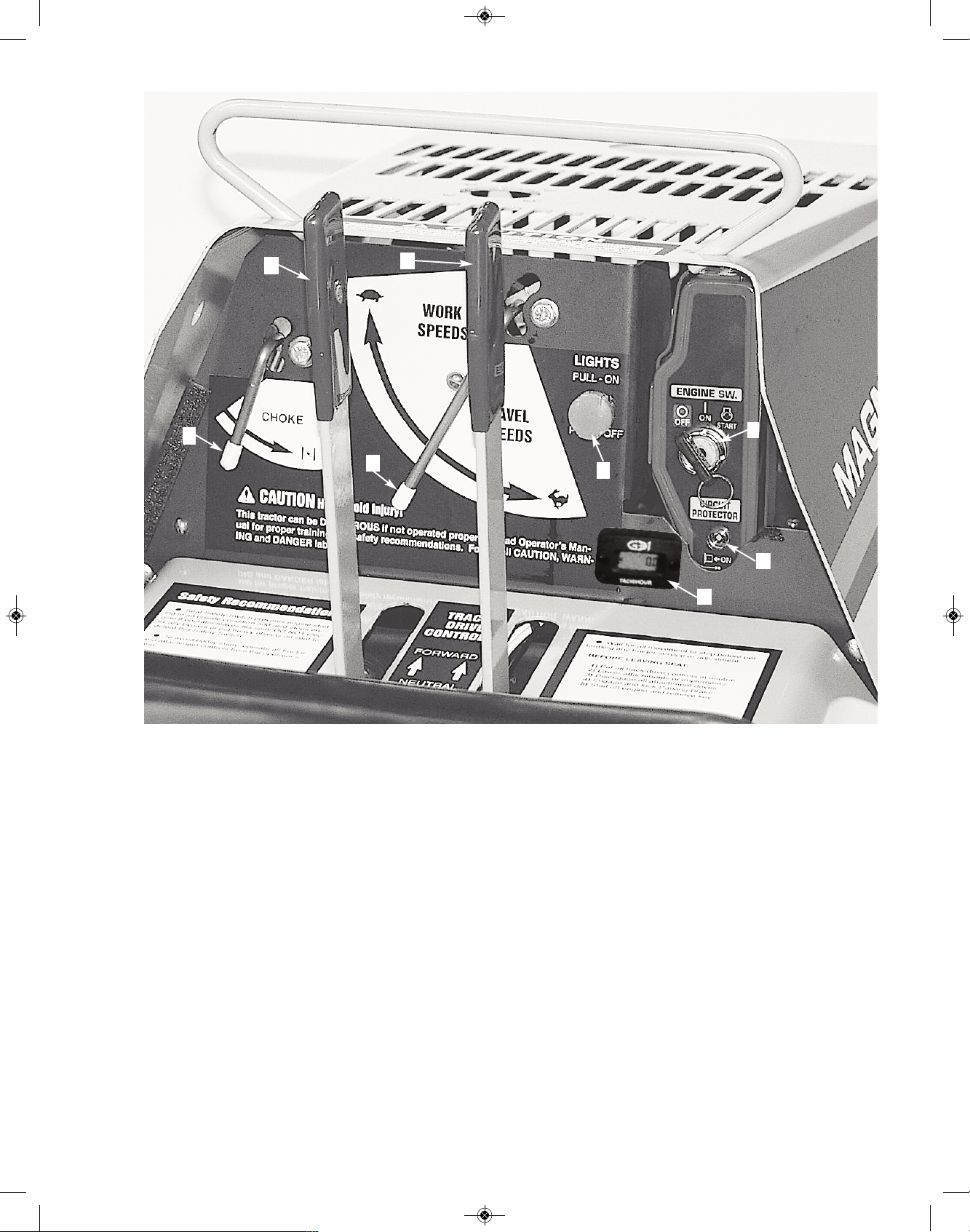
3- CONTROLS
& INSTRUMENTS
Learn the location and purpose of all Controls,
Instruments and Warning labels. Thoroughly
study the Operator’s Manual furnished by the engine manufacture and included with your Crawler
instructions.
A - LEFT TRACK
CLUTCH CONTROL
B - RIGHT TRACK
CLUTCH CONTROL
C - THROTTLE CONTROL
D - CHOKE CONTROL
E - HEADLIGHT SWITCH
F - KEY IGNITION SWITCH
G - CIRCUIT PROTECTOR
H - FUEL VALVE
I - PARKING BRAKE (not shown)
J - HOUR METER/TACH (if equipped)
11
A
B
C
D
E
F
G
J
RS1000 Operator Manual 1.01.19.qxp_Layout 1 4/24/19 12:41 PM Page 11
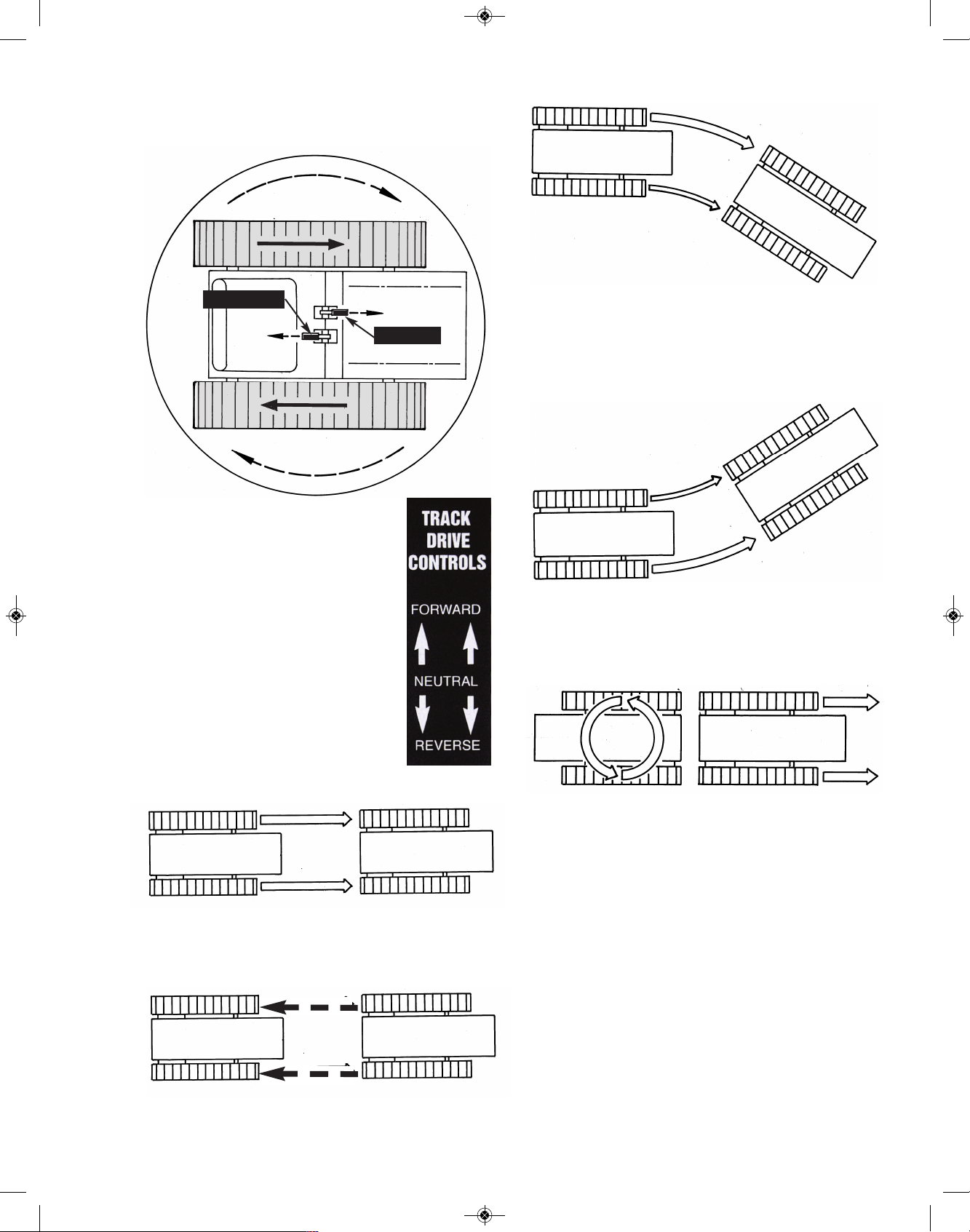
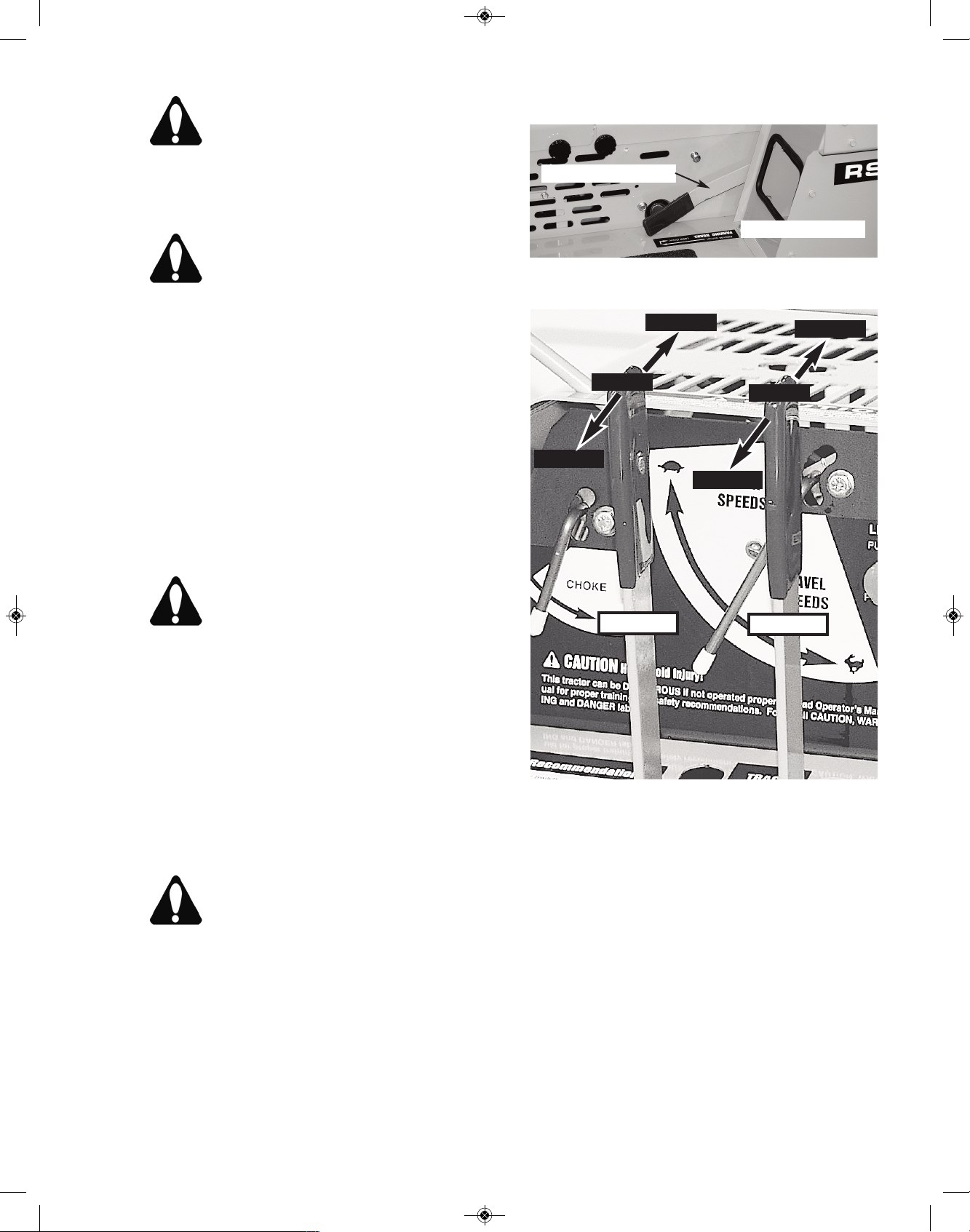
A & B - LEFT & RIGHT
TRACK CLUTCH CONTROLS
INTRODUCTION: The turn
demonstrated (above) is the key to
your Crawler’s superior maneuverability. It is accomplished with only
two controls, the A & B Left & Right
Track Controls. The illustrations
(below) show how to maneuver
your crawler in other turns.
MOVING FORWARD:
To move straight ahead, simultaneously push forward on both Left
and Right Track Controls.
MOVING REARWARD:
To move straight rearward, simultaneously pull
rearward on both Left and Right Track Controls.
T
URNING RIGHT:
To turn sharply right, push forward on Left Track
Control while holding Right Track Control in neutral.
TURNING LEFT:
To turn sharply left, push forward on Right Track
Control while holding Left Track Control in neutral.
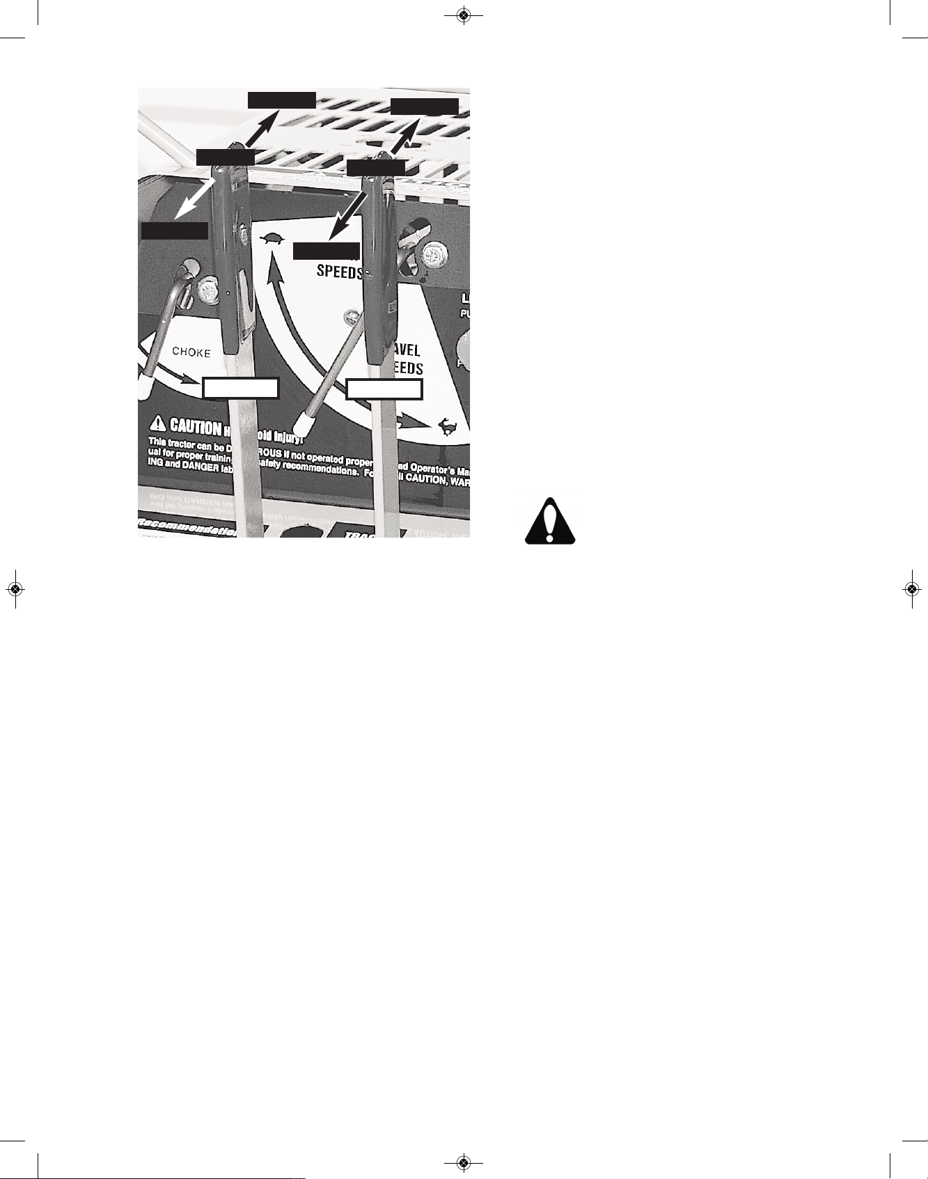
COUNTER-ROTATING TRACKS
To counter-rotate Tracks (tightest turn possible),
push one Track Control forward while simultaneously pulling rearward on the other Track Control.
NOTE: When either Track Control is “slowly” re-
leased, it will automatically return to neutral.
NEVER allow Track Controls to “snap-back” to
neutral. See OPERATION section of this manual
for further instructions.
12
A - Left
B - Right
RS1000 Operator Manual 1.01.19.qxp_Layout 1 4/24/19 12:41 PM Page 12
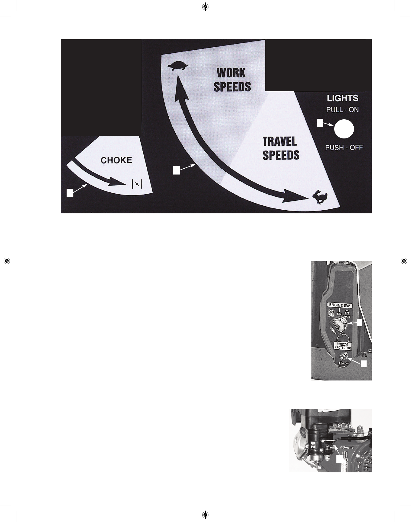
DASHBOARD CONTROLS
C - THROTTLE CONTROL
The Throttle is lever operated, rotating in a wide
arc. This arc is divided into two speed ranges; the
slower Work Speeds and the faster Travel
Speeds. Your Crawler has maximum “pushing
force” (maximum torque, according to the engine
manufacturer) at the mid-range speed but with a
declining level of torque as you increase your
travel speed. We advise using only as much throttle as needed for a particular application. If the
engine bogs down, please feel free to use more
throttle when you feel it is needed.
Though all crawlers by their design are somewhat
“rough riding”, you can minimize the “roughness”
by traveling at the lowest speeds when going over
hard surfaces.
D - CHOKE
The Choke Control is lever operated. Rotate the
lever counter-clockwise to increase engine choking; rotate clockwise to decrease engine choking.
(Consult engine manual for more information).
E - HEADLIGHT SWITCH
The Headlight Switch is a basic “Pull ON”, “Push
OFF” switch. Behind the Switch is a replaceable
Safety Fuse. When replacing, use a new fuse of
the same amps as the one being replaced.
F - KEY IGNITION SWITCH
Switch is activated by rotating key clockwise.
Turning it fully clockwise will engage engine starter
...release key and it will return automatically to the
RUN “ON” position. Turn
fully counter-clockwise to
OFF position to stop engine. Remove key.
G - CIRCUIT
PROTECTOR
The Circuit Protector protects the battery charging
circuit. (Consult engine
manual for more information).
H - FUEL SHUT OFF VALVE
The Fuel Shut Off
Valve Lever controls the fuel to the
carburetor. Turn it
OFF for transport
or when cleaning
carburetor. (Consult Engine Manual
for more information).
13
H
a
r
d
Su
r
fa
c
e
T
r
a
v
e
l
Ma
x
imu
m To
rq
u
e
D
C
E
H
F
G
RS1000 Operator Manual 1.01.19.qxp_Layout 1 4/24/19 12:41 PM Page 13
I - PARKING BRAKE
The Parking Brake acts both as a parking brake
and as an emergency brake.
To “engage” Parking Brake, pull Brake Handle up
firmly and loop it “up and over” the Carriage Bolt
provided...make sure handle edge is on top of Bolt
and behind “inside face” of Carriage Bolt.
To “disengage” Parking Brake, reverse the above
procedure and allow Brake Handle to rest on
Fender.
As the Parking Brake is also your emergency
brake, it’s extremely important to maintain its performance with daily inspection. See Service section of this manual for proper procedures.
EXTREMELY IMPORTANT:
As it’s mandatory to engage the Parking Brake be-
fore starting your crawler, always remember to
disengage it before driving away.
If you fail to disengage the Parking
Brake it will wear very rapidly and be
of no value in an emergency!!
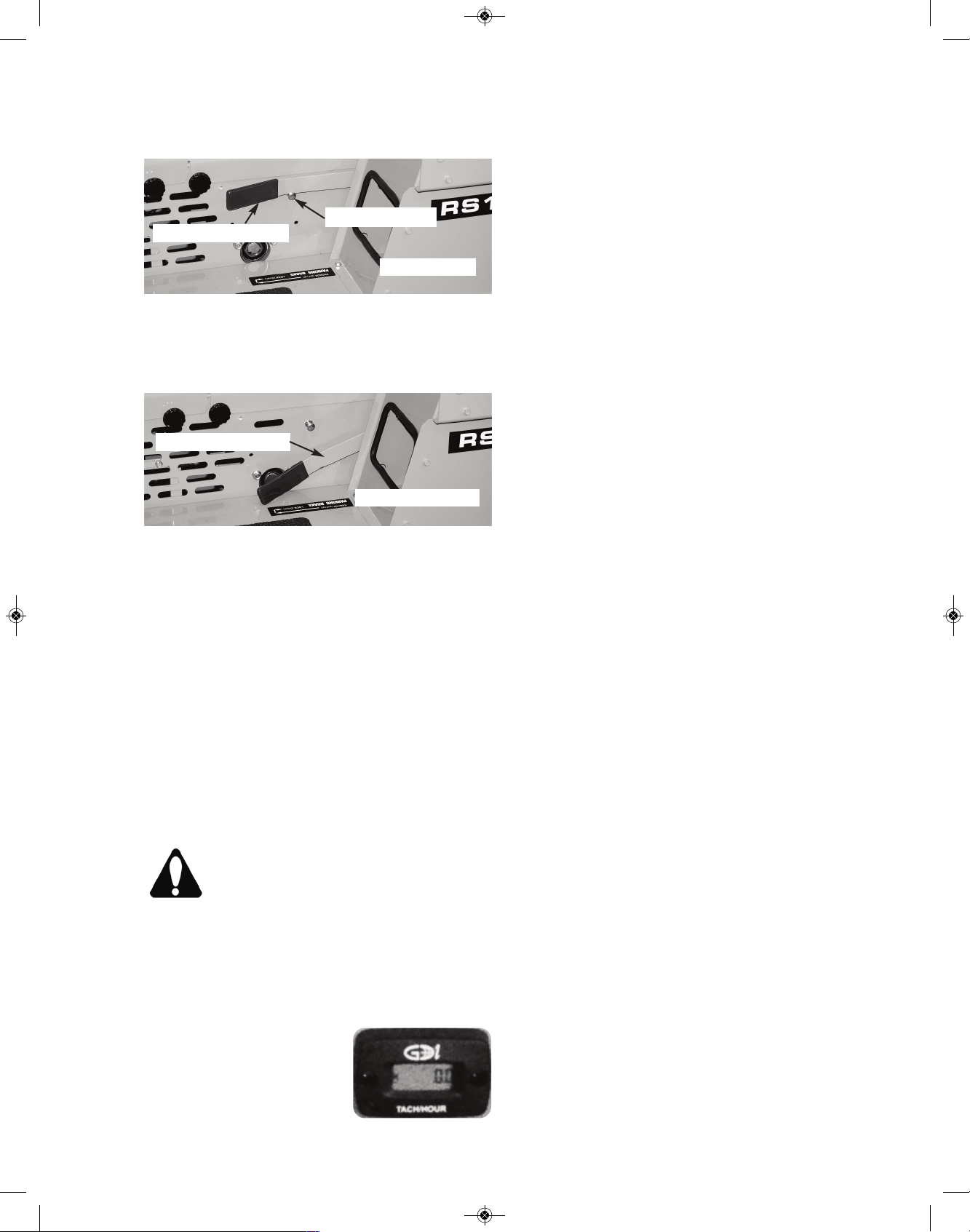
J - HOUR METER /TACH (If equipped)
The Hour Meter/Tach displays the hours run and the
RPM of the engine. Keeping
up with your maintenance of
your MAGNATRAC keeps it
running in top condition!
HOUR METER / TACH FLASH ALERT:
Flashes “CHG OIL” at 100 hour service
intervals and “LUBE” at 25 hour service intervals, the service interval is based on actual run
h
ours.
OPERATION:
Alerts begin flashing a warning 4 hours before service is due, and clear automatically 1 hour
afterward. Meter displays RPM while enigne is
running, hours while eningeis off.
FLASH SERVICE RESET:
Service alarms will automatically reset 1
hour after service interval.
14
DISENGAGED
I - Brake Handle
I - Brake Handle
ENGAGED
Carriage Bolt
RS1000 Operator Manual 1.01.19.qxp_Layout 1 4/24/19 12:41 PM Page 14

4- OPERATION
PRE-STARTING INSPECTION
Before you start your Crawler for the first time
each day, perform the following checks:
ENGINE COMPARTMENT
Check oil level.
Check air intake system.
Remove trash and oil/dirt deposits.
TRACKS, ATTACHMENTS, SHEET METAL
Check for bent, broken, or missing parts.
Check Track Springs.
HARDWARE
Check for loose or missing parts.
ELECTRICAL SYSTEM
Check for worn or frayed wires or loose
connections.
LUBRICATION
Check lubrication points shown in Periodic
Service section of this Manual.
GUARDS AND SHIELDS
Check for tightness and condition.
BATTERY COMPARTMENT
Remove trash.
Check cables for tightness and corrosion.
FUEL TANK
Check fuel level.
OPERATOR’S STATION
Check control levers for free movement.
Clean fenders and instrument panel.
Adjust Seat location to fit operator.
CAUTION - Before you start the engine:
Clear the work area of people and obstacles
C
heck the condition of the Crawler. (Prestart
inspection).
Be sure there is enough ventilation.
Be sure to know the correct starting and stop
ping procedure.
Sit in the Operator’s Seat.
PREPARE FOR ENGINE STARTING
1. Allow Left (A) and Right (B) Track Controls to
assume their natural “spring-loaded” center neutral positions.
2. Engage Parking Brake (I). (Make sure Brake
lever is pulled “up and over” round head of Carriage Bolt provided...make sure handle “edge” is
on top of this Bolt and behind its inside face).
3. Check that all Attachments are in the fully lowered position.
4. Make sure you are properly seated so Seat
Safety Switch will engage
STARTING THE ENGINE
1a. Cold Engine - Place the Throttle Control (C)
midway between the Slow and Fast positions.
Place the Choke Control (D) into the On (fully
choked) position.
1b. Warm Engine (normal operating temperatures) - Place the Throttle Control midway between the Slow and Fast positions. Place the
Choke Control into the Off (no choke) position.
2. Activate the Key Ignition Switch (F) by rotating
the key clockwise until starter engages. Release
the key as soon as the Engine starts ...Switch will
return to the Run “On” position.
NOTE: After starting a “cold” Engine, it may be
necessary to leave the Choke partially On for a
few minutes before moving it to the Off position
15
RS1000 Operator Manual 1.01.19.qxp_Layout 1 4/24/19 12:41 PM Page 15
C
AUTION: Do not crank the Engine
continuously for more than 10 seconds
at a time. If the Engine does not start,
allow a 60-second cool-down period between starting attempts. Failure to follow these
g
uidelines can burn out the starter motor.
CAUTION: If the Engine develops suffi-
cient speed to disengage the starter but
does not keep running (a “false start”),
the Engine rotation must be allowed to
come to a complete stop before attempting to
restart the Engine.
If the starter is engaged while the flywheel is rotating, the starter pinion and flywheel ring gear
may clash, resulting in damage to the starter.
If the starter does not turn the Engine over, shut off
starter immediately. Do not make further attempts
to start the Engine until the condition is corrected.
If the battery charge is not sufficient to turn over
the Engine, recharge the battery.
CAUTION: Do not attempt to jump start
the Engine with another battery. Start-
ing with batteries larger than those rec-
ommended can burn out starter motor.
WARM-UP PERIOD
Run Engine at half speed for 5 minutes.
Do not run Engine at fast, or slow idle.
Operate Crawler at less-than-normal loads and
speeds for the first 15 minutes.
WARNING: Lethal Exhaust Gases!
Engine exhaust gases contain poison-
ous carbon monoxide. Avoid inhaling
fumes, and never run the Engine in a
closed building or confined area.
NOTE: Assembled Crawlers are “run in”
under no load at the factory to properly
break-in their drive train.
TRAVELING
Disengage Parking Brake (I); Fully raise all Attachments to recommended traveling heights.
To move straight ahead, simultaneously push
both Left Track Control (A) and Right Track Control (B) forward.
To move straight to the rear, simultaneously pull
both Right and Left Track Controls rearward.
To turn sharply to the right, push Left Track
Control fully forward...leave Right Track Control in
neutral.
To turn slowly to the right, push Left Track Control fully forward while simultaneously pushing
“partially” forward on Right Track Control...the farther you push the Right Track Control forward, the
slower you will turn right.
16
DISENGAGED
I - Brake Handle
Reverse
Reverse
Forward
Forward
Neutral
Neutral
Control A
Control B
RS1000 Operator Manual 1.01.19.qxp_Layout 1 4/24/19 12:41 PM Page 16
To turn sharply to the left, push Right Track
Control fully forward...leave Left Track Control in
neutral.
To turn slowly to the left, push Right Track Control fully forward while simultaneously pushing
“partially” forward on the Left Track Control...the
farther you push the Left Track Control forward,
the slower you will turn to the left.
To counter-rotate Tracks, (shortest turn possible), push one Track Control forward while simultaneously pulling rearward on the other Track
Control. You may counter-rotate “clockwise” or
“counter-clockwise”; move in which ever direction
satisfies the job at hand.
Stopping the Crawler: The Right and Left Track
Controls are of the self-centering (neutral) type.
This allows you to simply release pressure on both
Track Controls to disconnect (declutch) active
power to the Tracks and come to a complete stop.
Never “snap” Track Controls back into neutral!
P
ARKING THE CRAWLER
1. Lower all Attachments to the ground.
2. Allow Right and Left Track Controls
t
o go “slowly” to neutral.
3. Engage Parking Brake.
4. Run Engine at half speed 2 minutes
without load.
5. Move Throttle Control to slow idle.
6. Turn Ignition Switch to Off.
IMPORTANT: If Engine stops under load, remove
load. Start Engine immediately. Run 30 seconds
at half speed before adding load.
CAUTION: When you park your
Crawler on a slope, put blocks against
tracks. Do not park Crawler with
tracks pointed downhill, always park
“cross-ways” to the hill!
STORAGE
Always store your MAGNATRAC in a garage,
shed or barn. If the only option is to park outside,
make sure to securely tarp the unit and park on a
flat surface with the parking brake engaged.
During freezing weather, park on a hard surface
to avoid freezing the Steel Tracks (if equipped) to
the ground. We recomend parking on rubber track
mats or using some inexpensive plywood. This will
keep moisture away from the steel tracks and extend the life of them. If Tracks are frozen to the
ground, be careful to avoid damage to the Tracks
and drive train when you try to move the Crawler.
We advise to turn off the fuel shut off valve and
run until the unit stops if going to store for a long
period of time. This is to ensure easy starting during the next season. Remember to turn ON the
fuel when ready for work the next time!
17
Reverse
Reverse
Forward
Forward
Neutral
Neutral
Control A
Control B
RS1000 Operator Manual 1.01.19.qxp_Layout 1 4/24/19 12:41 PM Page 17
5- FUELS
&
LUBRICANTS
FUELS
FUEL SPECIFICATIONS
Add fuel to fuel tank per engine manual specs.
Unleaded 86 octane or higher is reccommended per HONDA. Verify fuel shutoff valve is in the open position.
FILLING FUEL TANK
The Fuel Tank is located underneath the hood, on
the eninge.
Fill Fuel Tank at end of each day’s operation.
Fuel Tank capacity is 6.4 U.S. qts. or 1.6 gallons.
Use unleaded gasoline per Engine Owner’s Man-
ual.
CAUTION: Handle fuel carefully. Do
not fill fuel tank when the Engine is running. Do
not smoke while you fill fuel tank or work on fuel
system.
STORING FUELS
Keep fuel in a container in a protected area.
Water and sediment must be removed before fuel
gets to the Engine. Do not depend on fuel filters
to remove water.
If possible, install a water separator at the storage
tank outlet.
Store fuel drums on their sides with plugs up.
IMPORTANT: Keep all dirt, scale, water, or other
foreign matter out of fuel.
LUBRICANTS
ENGINE OIL
Check enclosed Engine Owner’s Manual and
closely follow their recommendations.
HYDRAULIC OIL (If equipped)
Use a premium quality hydraulic oil with maximum anti-wear properties, rust and oxidation
treatment. A high quality antiwear hydraulic fluid
designed for use in high pressure, high speed hydraulic pumps in industrial hydraulic systems. We
use an AW46 Hydraulic Oil. (ISO 46). An ISO of
46 is good in standard temperatures. If operated at exteme hot or cold temperatures,
please consult a local oil shop for an oil viscosity best suited for your conditions.
If the above specifications can not be found
consult with a local tractor/equipment dealership or oil supplier for other brands of hydraulic oil suitable for loaders, backhoe, and
hydraulic drive systems.
Fill Hydraulic Oil Tank through #616 breather,
on the top of the hydraulic tank, behind the operator seat. Check level by “eye check”, it should be
a few inches from the top...remove breather with
a crescent wrench at the black nut and hand
tighten once full!
Approximately 2 gallons of hydraulic fluid
fills the hydraulic reservoir to the proper
level (when empty & no hydraulic cylinders
are attached).
GREASE
Use premium quality SAE Multi-Purpose Grease
in a grease gun with a flexible “nose” to lubricate
grease zerks throughout the MAGNATRACS pivot
points.
STORING LUBRICANTS
Store lubricants in clean containers in an area protected from dust, moisture, and other contamina-
tion.
18
RS1000 Operator Manual 1.01.19.qxp_Layout 1 4/24/19 12:41 PM Page 18

6- LUBRICATION
&
PERIODIC SERVICE
LUBRICATION AND SERVICE
INTERVALS
Recommended service intervals are for normal
conditions. Service more often if Crawler is operated under more difficult conditions such as high
temperature, dust, etc. Use only quality lubricants
at intervals specified in this manual.
PERIODIC SERVICE CHART
Air Cleaner(s) - Service per instructions in En-
gine Owner’s Manual.
Engine Oil - Service per instructions in Engine
Owner’s Manual
Battery - Change as needed. Approximately every
3 years.
1ST USAGE
1ST USAGE
Hydraulic Oil - Attach any additional attach-
ments first (Grapple, backhoe, rear hitch,
etc.) Check level on a flat & level surface;
with equipment on the ground (retract all
possible cylinders), level should be approx. 5” away from the top of the tank.
Add additional fluid if needed.
Engine Oil - Check enigne oil level before use to
make sure oil level is at acceptable level
on the dipstick. Add additonal if needed.
NOTE: First oil change for a new Engine
is at 5 hours
Fuel - Add fuel to fuel tank per engine manual
specs. Unleaded 86 octane or higher is
reccommended per HONDA. Verify fuel
shut-off valve is in the open position.
EVERY TEN HOURS
EVERY TEN HOURS
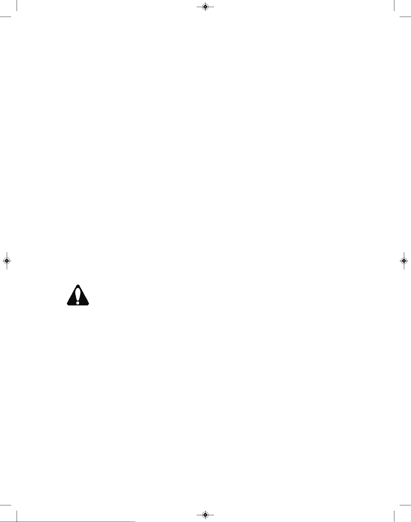
Grease Fittings - Lubricate all grease fittings
per location instructions in manual of
each attachment you have mounted on
your MAGNATRAC. Recommended
grease: Multipurpose NLGI 2 Grade
Lithium Complex, ISO VG 220.[Clean
grase fittings and area around them before servicing].
Clean area around each grease fitting on Front
Idler and Rear Drive Assemblies. Grease each
grease fitting until you feel back pressure building.
A small breakdown of how many grease fittings
are on the RS1000 and various Attachments is as
follows:
RS1000 with Steel Tracks: 6
RS1000 with Rubber Tracks: 10
Note: 4 are located on the front idlers &
rear drives and 2 are on the #1791 Rear
Bearings. (shown on the next page)
For all others, please see each individual
attachment for the quantity of grease fittings.
As a standard guide, there will be a grease
fitting for each Axle/Pin that you see on a
particular attachment. (See below).
HFH15 Front Hitch: 2
D1060 Backhoe: 14
D1060UG Backhoe: 18
HRH35 Rear Hitch: 2
Rubber Track Idlers: 4
#1791 Bearing Assemblies: 2
Lubricate the “grease fitting” in each #1791
Bearing Assembly. NOTE: The #1791
Bearings are the hardest working Bearings
in your RS1000, never spare proper lubri
cation and maintenance! See picture on
the next page.
19
RS1000 Operator Manual 1.01.19.qxp_Layout 1 4/24/19 12:41 PM Page 19
EVERY FIFTY HOURS
EVERY FIFTY HOURS
Engine Oil
Drain and refill per recommendations in
Engine Owner‘s Manual.
NOTE: Change Engine oil every 25 hours
if you’re working under constant heavy
loads or extremely dirty conditions.
Filters
Replace Engine Air Filter with filter recommended in Engine Owner’s Manual.
Tracks and Track Sprockets
Pressure wash track system, including:
Front Idler and Rear Drive Sprockets.
Track Tension
Maintain 1-3/8” overall length of #1806
Spring on each Track.
Check Service section of this Manual for
complete explanation and Track Tensioning procedures.
Rear Drive Chain Tension
Maintain proper chain tension in Crawler’s
Rear Drive. Check Service section of this
Manual for complete Rear Drive Chain
Tensioning procedures.
Rear Drive Chain Lubrication
Use SAE 30 motor oil in pressure oil can.
Thoroughly lubricate each Drive Chain.
[TIP: Drive Crawler forward approximately
six feet stopping to oil the Chain every
foot]. Don’t forget to do both Drive Chains!
T
ip: wipe the chain down after oiling to keep oil
spatter to a minimum.
Engine Drive Chain Tension (If equipped)
M
aintain proper chain tension in Crawler’s
Engine Drive Chain. Check Service section of this Manual for complete Engine
Drive Chain tensioning procedures.
General Once-Over
Check for loose nuts and bolts and any
signs of premature wear. Correct any
problems immediately. Contact factory
with any questions or requests for help.
EVERY 200 HOURS
EVERY 200 HOURS
Fuel Tank
Remove and drain tank of any water or
sediment. Clean or replace the in-tank
fuel filter.
Fuel Filter - Replace with new Fuel Filter at this
time: Filters can be purchased through the
Struck Corporation or through local engine
dealers.
Hydraulic Oil (If equipped) - Run the RS1000 for
approx. 5 minutes at idle, shut off. Drain
system by angling the 90 degree fitting on
the bottom right of the hydraulic oil tank.
NOTE: Drain when fluid is warm. Block up
the right front corner of Crawler a few
inches to get oil to flow completely to drain
opening. Refill with approx. 2 gallons of hydraulic fluid. Fill the hydraulic reservoir to
the proper level. (See PP35 Power Pack
section of the attachment manual)
Enigne Spark Plugs - Replace Engine Spark
Plugs with spark plugs recommended in
Engine Owner’s Manual.
20
Zerk
#1791 Bearing Assembly
RS1000 Operator Manual 1.01.19.qxp_Layout 1 4/24/19 12:41 PM Page 20

7- SERVICE
In the following Service section of this Manual, you
w
ill be required to do various assembly and dis-
a
ssembly procedures. Each section will try to remind you of safe procedures, but the best safety
device is still the mechanic himself.
CAUTION: Try to do your work in a
level, open area away from people and
obstacles.
1. Pay attention to what you are doing..the parts
you will be handling can be heavy, sharp or could
pinch. Always wear heavy gloves when handling
the Tracks and similar sharp, pinching parts.
2. When you are required to block your crawler to
raise it off the ground, make sure you use strong
blocking materials and think out how the Crawler
will safely balance on blocking. To protect your-
self and your Crawler from damage, check
“Safe Blocking Diagram” on front page of this
Manual!
Never be too proud to ask a friend or neighbor for
help...especially when blocking up your Crawler
or working with the Tracks.
As always, the factory is your best source for competent service advice and explanations of any
service procedures that are unclear...always feel
comfortable calling for whatever advice you may
need!
ENGINE
Your Crawler comes with a complete Engine
Owner’s ManuaI. It provides complete operation
and maintenance instructions for your engine. If
further help is needed, contact your local engine
dealer...he’s listed in the telephone “Yellow Pages”
under “Engines, gasoline”.
STARTER
IMPORTANT: Don’t operate starter switch longer
than 10 seconds at a time. If engine does not start
within 10 seconds, wait 60 seconds before trying
to start again. After a false start, do not turn starter
button until Engine has stopped turning.
If the starter will not operate or operates slug-
g
ishly, check for the following:
Run down battery.
Dirty, loose, or corroded cables and wires.
Engine oil viscosity too heavy.
BATTERY
Your Crawler has a 12 volt, negative-grounded
system with one battery (battery not included on
basic recoil start models).
BATTERY PRECAUTIONS
CAUTION: Sulfuric acid in batteries is
a poison and could cause severe burns.
Avoid contact with skin, eyes, and
clothes. When you work around batteries, protect eyes and face from battery fluid and
explosion.
Antidotes for Sulfuric Acid:
EXTERNAL
1. Flush skin well with water.
2. Flush eyes for 15 minutes.
3. Get medical attention immediately.
INTERNAL
1. Drink a large amount of water or
milk.
2. Then drink milk of magnesia, beaten
eggs, or vegetable oil.
3. Get medical attention immediately.
CAUTION: Keep flames and sparks
away from battery.
Do not use booster cables or adjust battery terminal connections unless you know the correct procedure.
When you charge a battery or use a battery in a
closed space, be sure there is enough ventilation.
Keep batteries where children cannot reach them
with vent caps tight and level.
21
RS1000 Operator Manual 1.01.19.qxp_Layout 1 4/24/19 12:41 PM Page 21
COLD WEATHER BATTERY SERVICE
During cold weather, keep electrolyte in battery at
correct level (if applicable). Keep battery fully
c
harged.
BATTERY STORAGE
If Crawler will be stored for more than 30 days, remove battery. Keep it fully charged.
BATTERY MAINTENANCE
1. Remove corrosion from terminals with
a stiff, non-metallic brush.
CAUTION: Use care when cleaning
terminals so that you do not “short them
out” with metallic brushes, scrapers,
screwdrivers etc.
2. Clean battery with a baking soda solution (1/4 pound in a quart of water)...best done
with battery removed from crawler.
3. Flush battery and compartment with
clear water.
4. Check electrolyte level (if applicable).
Fill each cell to bottom of filler neck with distilled
water or clean, soft water (not hard water).
5. Put petroleum jelly on terminals. Maintain protective cover on “positive” (+) terminal of
battery.
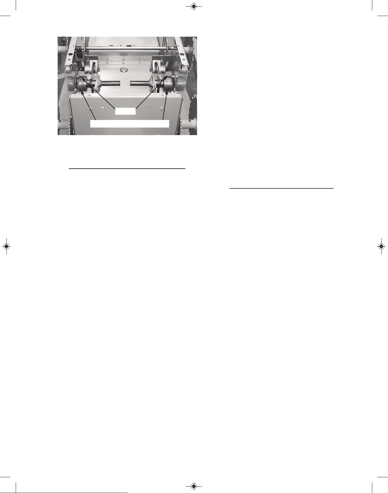
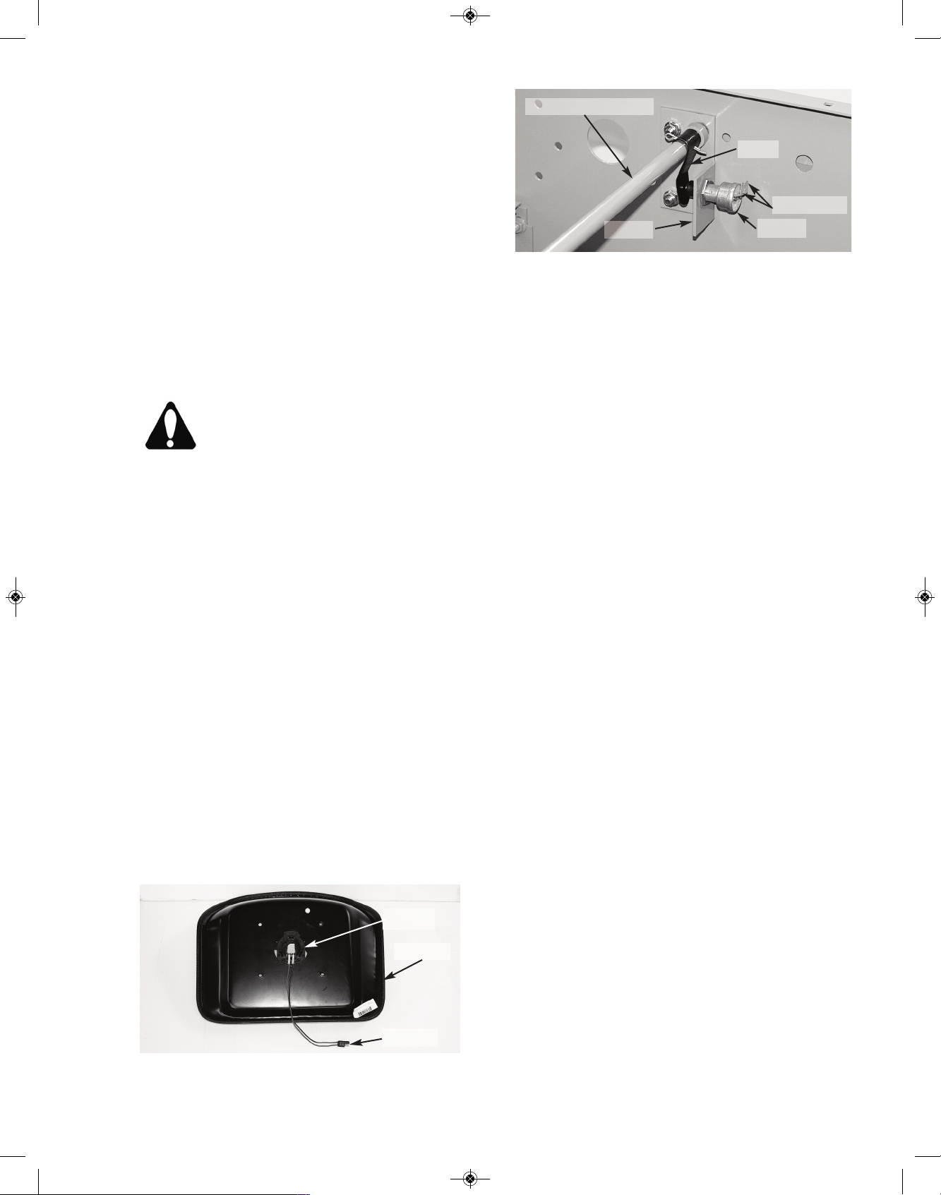
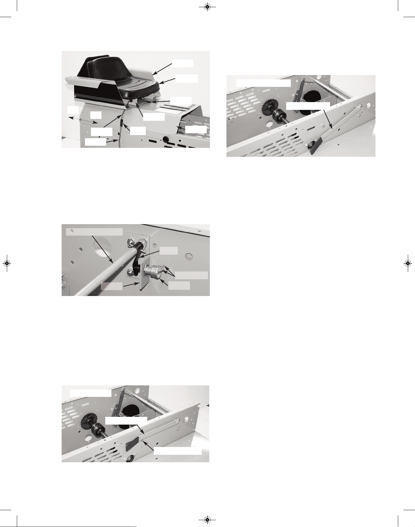
SAFETY INTERLOCK SWITCHES
Two Switches, one on underside of the #933A
Seat and the other one on the Brake Lever Rod
inside Crawler.
These switches are used in the Crawler’s electrical system as safety devices. They detect if the
operator is properly seated, and that the Parking
Brake is engaged before the Crawler can start.
To check either the #1162 Seat Switch or the
#1148 Parking Brake Switch, you must remove
the electrical connectors attached to each switch’s
terminals and connect a continuity tester to its terminals (a simple flashlight type continuity tester
would be fine).
SEAT SWITCH TEST
Remove #933A Seat from its #1674 Seat Mounting Bracket. Then remove the electrical connectors attached to each of the #1162 Seat Switch’s
two terminals.
1. By pushing down on the center of the
seat the Seat Switch should “open”. A continuity
tester, attached to the two terminals of the Switch,
should have its light Off at his time!
2. With pressure removed from the seat,
the Switch should “close”...the light should be On!
If both of the above conditions are not met, the
Switch is defective and must be replaced. When
test is completed, remove continuity tester and replace original electrical connectors on both terminals of Seat Switch. Remount seat to its Mounting
Bracket.
Reassemble the Seat Assembly to your Crawler
and reconnect it’s Plug.
At this time following recommended safe starting
procedures, start the Engine and check Seat
Switch response...readjust if necessary.
22
#1162
#1829
#933A
Brake Lever Rod
#440
#1148
#1674
Terminals
RS1000 Operator Manual 1.01.19.qxp_Layout 1 4/24/19 12:41 PM Page 22
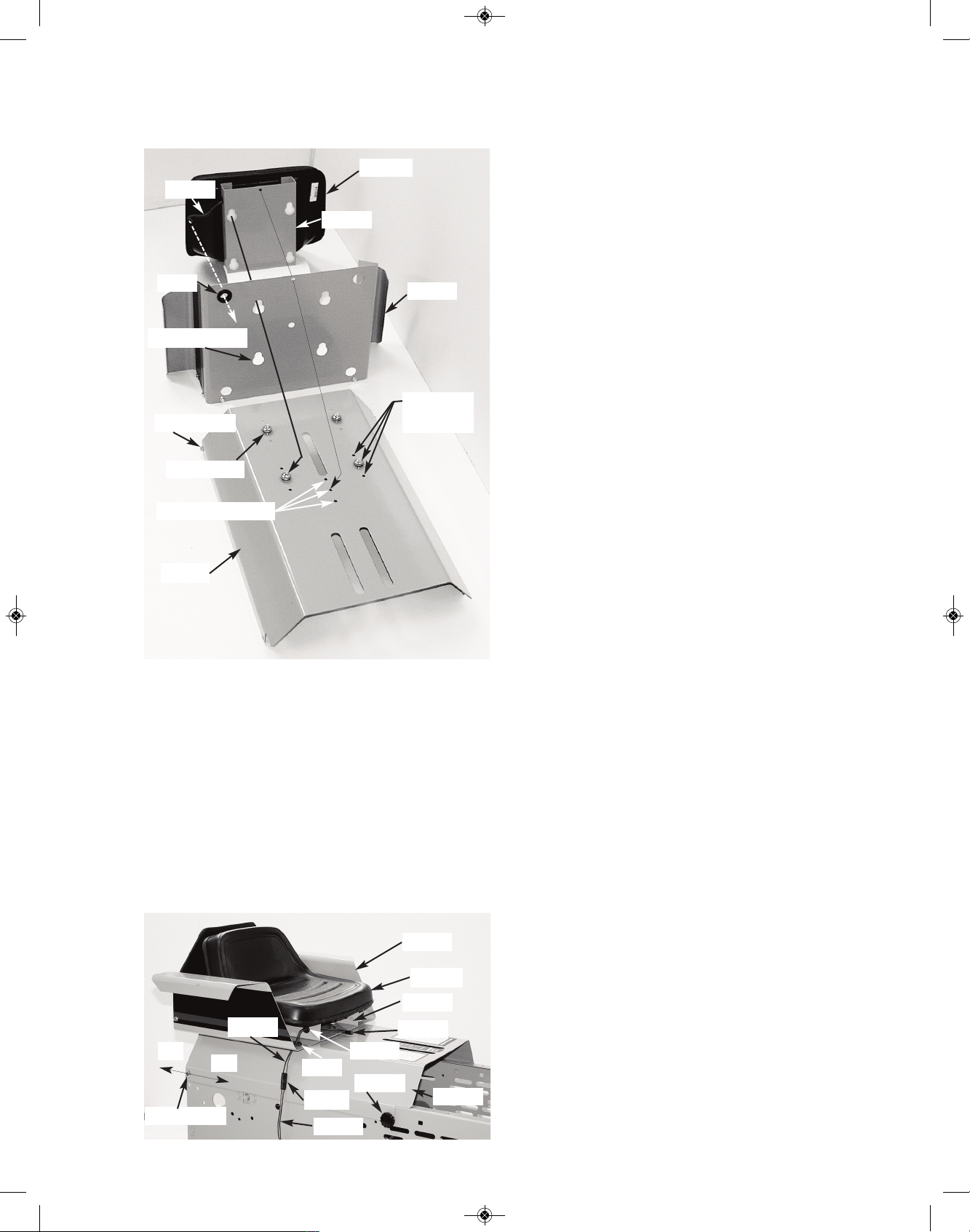
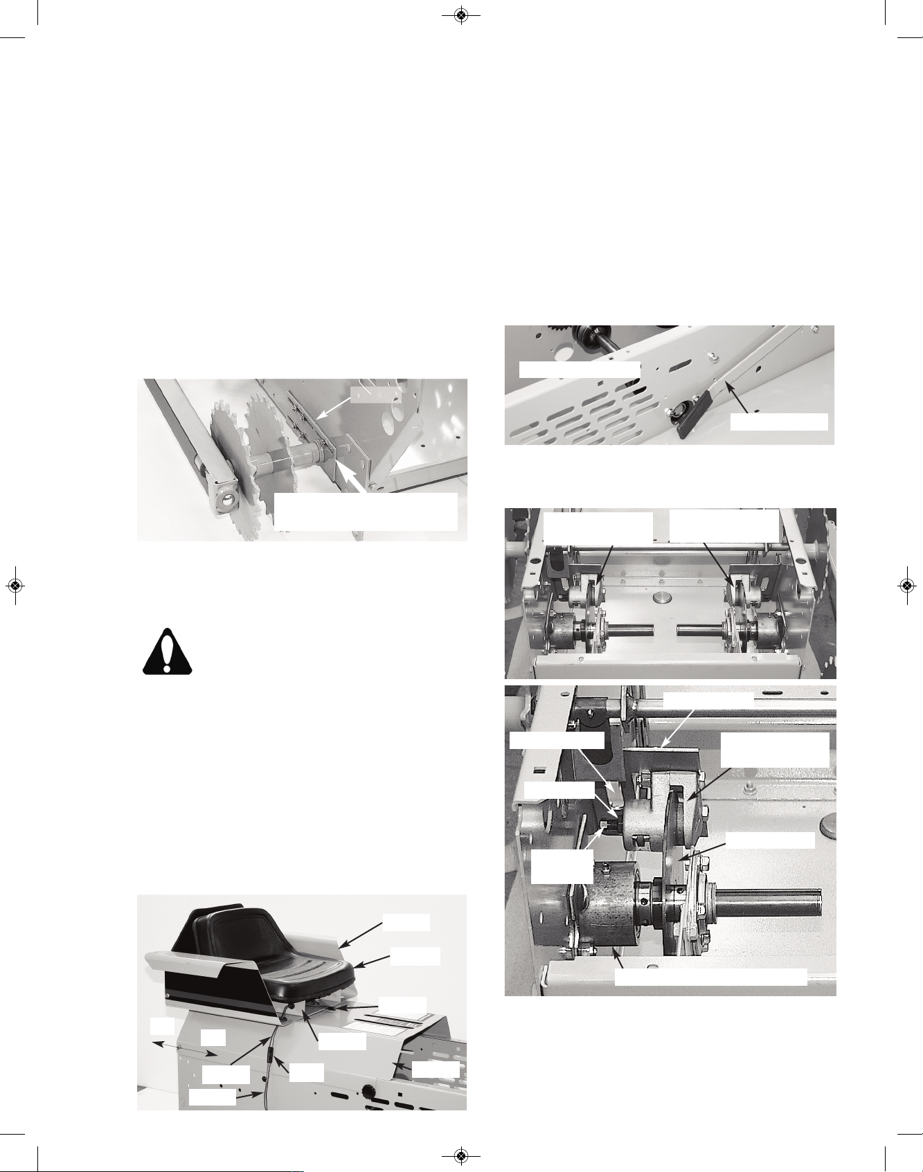
SEAT & REAR COVER
ASSEMBLY
Your Seat & Rear Cover Assembly is made up of
three main components: The #1674 Mounting
Bracket (with attached #933A Seat) and #1625
Arm Rests mounted to #1608 Rear Cover. They
are held together with four “keyhole slots” over
four “posts”. The “posts” can be located in three
different positions to satisfy the operator’s “seating
comfort”.
When all components are nested together they
will share a common “seat pin hole” that will lock
the assembly together with a #1688 Seat Pin.
T
here are two methods to remove the Seat As-
sembly. One is by removing the Assembly as a
complete unit (It weighs about 45 lbs.). The second method takes longer but allows you to disassemble the unit into three components that weigh
a
bout 15 lbs. each. Both methods are explained
below...the choice is yours.
METHOD 1 - Seat Removal
Fully open the Hood by loosening a few turns of
the two #1866 “threaded” Knobs (located at lower
rear of Hood) and then rotating fully forward. Disconnect the #1824 & 1825 Wires at their mating
Plug. Remove the two #1866 “threaded” Knobs at
lower front edge of #1608 Rear Cover. Slide the
complete Seat Assembly rearward and remove.
Seat Assembly:
To replace your Seat Assembly “reverse” the steps
above.
1) Upon completion of reassembly, make sure
that #1824 Wire & Plug pass through #1854 &
#278 Grommets and connects to mating #1825
Wire & Plug.
2) Make sure “front top edge” of #1608 Cover
rests on top of “lip” that protrudes rearward out of
lower section of #1618 Dash.
3) Close Hood and secure it and Cover Assembly
with #1866 Knobs.
METHOD 2 - Seat Removal
Fully open the Hood by loosening a few turns the
two #1866 “threaded” Knobs (located at lower rear
of Hood). Rotate Hood fully forward until Chain
holds it. Disconnect the #1824 & 1825 Wires at
mating Plug. Draw #1824 Wire & Plug out of #278
Grommet. Remove #1688 Seat Pin and slide “forward” the #1674 Mounting Bracket with #933A
Seat and lift up to remove. Take #1625 Arm Rests,
slide forward and lift up to remove. Remove the
two #1866 “threaded” Knobs on front lower edges
of #1608 Cover. Slide the Cover rearward and remove.
Seat Assembly:
To replace your Seat Assembly “reverse” the steps
above.
1) Upon completion of reassembly, make sure
that #1824 Wire & Plug pass through #1854 &
#278 Grommets and connect to mating #1825
Wire & Plug.
2) Make sure “front top edge” of #1608 Cover
rests on top of “lip” that protrudes rearward out of
lower section of #1618 Dash.
3) Close Hood and secure it and Cover Assembly
with #1866 Knobs.
23
#933A
#1824
#1674
#1625
#1608
3 Seat
Positions
Seat Post
Keyhole Slot
#278
Seat Pin Holes
Body Post
#1625
#933A
#1608
#1688
#1674
On
Off
#1829
#1825
Plugs
#1854
#278
Body Post
#1866
RS1000 Operator Manual 1.01.19.qxp_Layout 1 4/24/19 12:41 PM Page 23
PARKING BRAKE SWITCH TEST
Begin your procedure by parking your Crawler on
an open, firm, level surface. Shut off engine and
engage Parking Brake. Open Hood and swing
fully forward. Remove #1688 Seat Pin. Remove
#933A Seat & #1674 Mounting Bracket, #1625
Arm Rests, and #1608 Rear Cover. NOTE: Be
sure to disconnect the “mating” #1829 and #1825
Seat Wires at their common Plug.
Disengage Parking Brake. Remove the two electrical wire plugs from their #1148 Parking Brake
Switch and connect a continuity tester to its two
terminals.
(1) With “plunger” of #1148 Parking Brake Switch
not depressed, the light of the continuity tester
should be On. With “plunger” of Parking Brake
Switch fully depressed, the light of the continuity
tester should be Off.
(2) When the Parking Brake Lever is pulled “upward” and looped “up and over” the Carriage Bolt
p
rovided into an “engaged” position, Parking
Brake Switch should be “open” (the result of contact with the rotated #440 Leaf Spring). The light of
the continuity tester should be Off!
(3) When the Parking Brake Lever is released
and put into it’s “disengaged” mode (Lever should
be free to touch Left Fender) the Parking Switch
should be “closed” (the Leaf Spring would have
rotated back and away). Continuity light should
now be On!
If both conditions of procedure (1) (above) are not
met, replace Parking Brake Switch. If both conditions of procedure (1) are met, but the conditions
of procedure (2) & (3) are not met, you must adjust
the “horizontal location” of the #1148 Switch in its
#1620 Bracket.
The #1148 Parking Brake Switch is secured “front
to rear” in it’s #1620 Bracket with hex nuts.
Adjust Switch’s location “front to rear” to meet requirements (1), (2) and (3) (above) by relocating
its two hex nuts.
When adjustment is completed, tighten Switch’s
hex nuts...terminals on Switch should point
straight up. Remove continuity tester and replace
electrical plug on terminals of Switch. Replace
Seat & Mounting Bracket, Arm Rest and Rear
Cover Assembly...check that it is positively latched
with #1688 Seat Pin! Close Hood and secure it
and Rear Cover with #1866 threaded Knobs.
NOTE: Be sure to reconnect “mating” #1829 &
1825 Seat Wires at their common Plug.
At this time, following recommended safe starting
procedures, start the Engine and check Parking
Brake’s Switch setting...readjust if necessary.
24
Brake Lever Rod
#440
#1148
#1620
Terminals
ENGAGED
Carriage Bolt
DISENGAGED
#1625
#933A
#1608
#1688
#1674
On
Off
#1829
#1825
Plug
Brake Lever
Brake Lever
RS1000 Operator Manual 1.01.19.qxp_Layout 1 4/24/19 12:41 PM Page 24

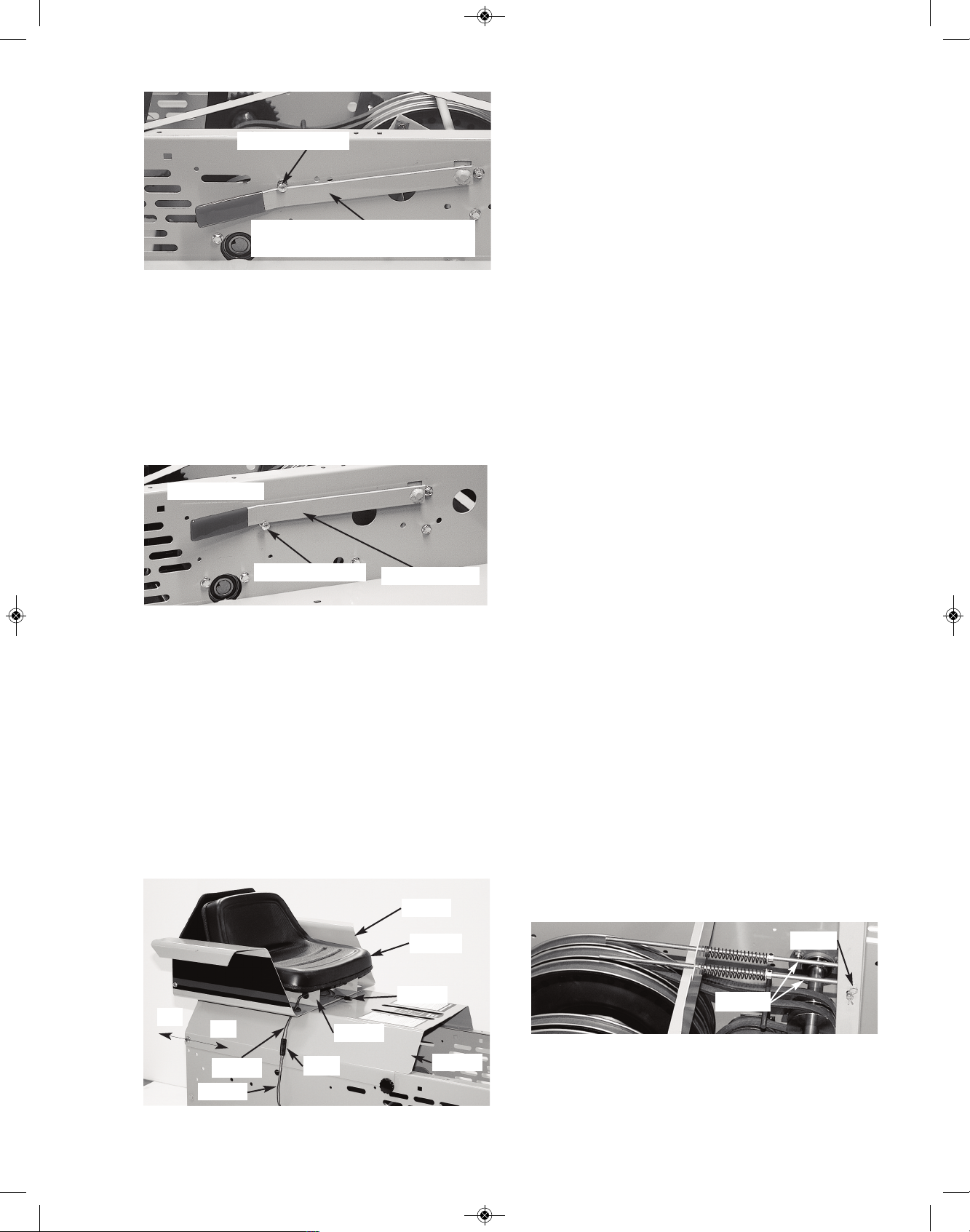
REAR DRIVE CHAIN TENSIONING
The #1805 Rear Drive Chains (#50 Roller Chain)
are tightened by increasing the center distance
between the movable #2065 Rear Axle and the
f
ixed #2048 Sprocket & Shafts.
NOTE: If you have the Rubber Track System
design, the sprockets will look differrent from
the ones shown in the next few pages, but the
rear drive tensioning procedure will still be the
same.
Begin your Drive Chain Tensioning procedure by
driving Crawler onto a firm, level surface. Shut off
Engine and dismount...do not “engage” Parking
Brake Lever.
[Though not absolutely necessary, it’s extremely
helpful in the following procedure to block your
Crawler up and remove its Tracks...see Track Removal section of this Manual for instructions].
Open Hood and swing fully forward; remove
#1688 Seat Pin. Remove Seat & Bracket, Arm
Rests and Rear Cover. Remove the #1636 Right
& Left Chain Guards from left and right sides of
Crawler.
Do a thorough washing and cleaning of the #1805
Chains and mating Sprockets with a powerwasher
or a stiff brush. The Sprockets and their mating
Drive Chains must be clean to give proper chain
adjustment. [Remove the Drive Chains and soak
in penetrating oil overnight if stiff].
From “outside” the Crawler’s body, loosen (but do
not remove) the five nuts on each (Left & Right)
#1611 Front Axle Plate. Similarly loosen, but do
not remove the four nuts on each (Left & Right)
#1656 Rear Axle Plate. NOTE: loosen the Carriage Bolt “nuts” from inside of body, all others
from outside.
On each side, from inside body, rotate each #2043
Pulley Assembly. Check that each #1850 Drive
Chain is moving smoothly and that it is free of debris.
[TIP: It will ease rotating the Pulley Assemblies
(above) if you follow the procedure for “Removal Steering Clutch Belts” in Service section of this
Manual. Replace Belts per “Installation - Steering
Clutch Belts” in Service section of this Manual
after you have completed your chain tensioning].
To tighten the Drive Chains, start rotating clock-
wise the Locknut located on left and right lower
rear of Body. To draw Rear Axle back evenly, turn
one Locknut 1/4 turn, then go to the other side and
tighten the other Locknut 1/4 turn...use this back
and forth procedure until both #1805 Drive Chains
are reasonably tight...not “bow-string” tight, but
about a 1/4” of “sag” in the slack strand when the
balance of the chain is taught.
NOTE: While doing the above procedure, make
sure you rotate each #1650 Rear Track Sprocket
25
#2048
#2065
#1656
#1611
Carriage Bolts
Locknuts
#1637
#1636
#1650
#1805
“Sag”
Locknuts
#1805
#1650
#1805
#2043
#1805
#1650A
RS1000 Operator Manual 1.01.19.qxp_Layout 1 4/24/19 12:41 PM Page 25
A
ssembly (left side & right of body) a full revolution
after each 1/4 turn of its respective Locknut. This
will determine if there is a slight “high spot” in one
of the (#1805 Chain) mating sprockets...if so, use
the “high spot” location for your point of tighteni
ng. When satisfied that both Drive Chains are
tightened evenly, retighten the four Bolts holding
the #1656 Rear Plates on left & right side of Body.
Thoroughly lubricate your Drive Chains at this
time.
Replace the #1636 Right & Left Chain Guards
using original Cap Screws, #1637 Spacers, and
Nuts . Replace Seat Assembly, Arm Rests and
Rear Cover and close Hood...secure all with
#1866 “threaded” Knobs.
Using a “flat-nosed” punch and hammer, push the
#1611 Front Axle Plate (located on both sides of
Body) rearward till it hits a solid stop. NOTE: in the
work done in steps above, this Plate may have al-
ready worked its way rearward. To
check, push Plate forward from the rear,
then push it back the required 3/16” distance.
NOTE: Though this is a simple adjustment, it’s
proper execution now will result in extremely
stable Track performance in the future!
If you have removed your Tracks, reassemble
them on your crawler at this time using the “Track
Replacement” instructions in Service section of
this manual...make sure to properly tension them.
PARKING BRAKE ADJUSTMENT
B
egin your procedure by parking your Crawler on
an open, firm, level surface. Shut off Engine, engage your Parking Brake Lever and dismount.
Raise Hood and rotate it fully forward, then remove the #1688 Seat Pin. Remove the #933A
S
eat & #1674 Mounting Bracket, #1625 Arm
Rests, and #1608 Rear Cover. NOTE: Disconnect
the “mating” #1829 and #1825 Seat Wires at their
common Plug.
Put the Parking Brake Lever in the disengaged position...end of Lever should be free to touch top of
Left Fender.
Loosen Jam Nut on the #225L Left & #225R
Right Disc Brake Calipers a few turns to free their
Adjuster Pins for rotation (see two Photos below).
With Brake Lever firmly touching underside of
Carriage Bolt, set each Brake’s tension by rotating
it’s Adjuster Pin clockwise until the the Pulleys on
each side are not able to be easily rotated by
hand.
26
#1802 Disk
Jam Nut
Wrench Slot
DISENGAGED
Push #1611 fully to rear,
approximately 3/16”!
#1611
#1625
#933A
#1608
#1688
#1674
On
Off
#1829
#1825
Plug
Brake Lever
Adjuster
Pin
#225L Disc
Brake Caliper
#225R Disc
Brake Caliper
#225L Disc
Brake Caliper
#1792 Yoke
#1791 Bearing Assembly
RS1000 Operator Manual 1.01.19.qxp_Layout 1 4/24/19 12:41 PM Page 26
Tighten each of these Brake Assemblies by holding their Adjuster Pin “motionless” with one wrench
while tightening their respective Jam Nut securely... a Wrench Slot is provided in each #1792
Yoke (see Photo previous page, lower right).
Engage Parking Brake by pulling up on Brake
Lever and draw it up, over, and behind the head of
the Carriage Bolt stop.
NOTE: In the process of making Brake adjustments, try to keep both Brakes synchronized with
each other for even braking! CHECK WITH FACTORY IF YOU HAVE ANY QUESTIONS REGARDING YOUR BRAKE ADJUSTMENTS!
Close Hood, then Replace Seat Assembly, Arm
Rests and Rear Cover...secure all with #1866
“threaded” Knobs. Reconnect mating #1829 &
1825 Plugs.
TRACK CLUTCH BELTS
The following segment is divided into three sect
ions:
1) Belt Removal.
2) Belt Installation.
3) Belt Adjustment.
It’s suggested that you read all three sections that
follow to gain an overview before you begin any
work. You can then return to the sections that
apply to the job you’re doing.
NOTE: In the following photos many are “cutaways” of an actual crawler which were created to
best illustrate the points covered in the following
instructions. Though the components are actual
crawler parts, many associated parts are missing.
SPECIAL NOTE: Though all six Track Clutch
Belts are identical and carry the same part number
(#2078), for simplicity they are designated in the
following drawings and descriptions as Belts #1
through #6. In a similar manner, the Pulleys have
their own part numbers (#2043 - 14” dia. and
#2041B - 3” dia.), but in the following instructions
they will be designated as Pulleys AA through LL
Begin your procedure by parking your Crawler on
an open, firm, level surface. Shut off Engine, engage your Parking Brake Lever and dismount.
Raise Hood and rotate it fully forward; remove the
#1688 Seat Pin. Remove the #933A Seat & #1674
Mounting Bracket, #1625 Arm Rests, and #1608
Rear Cover. NOTE: Be sure to disconnect the
“mating” #1824 and #1825 Seat Wires at their
common Plug. (see Photo at left)
Pull the #910 Hitch Pins and remove both #1638
Spring Rod assemblies...leave Springs, and Collars in place on each Rod.
27
#1638
#910
#1625
#933A
#1608
#1688
#1674
On
Off
#1829
#1825
Plug
Carriage Bolt
Brake Lever firmly touching
underside of Carriage Bolt
Carriage Bolt
ENGAGED
Brake Lever
RS1000 Operator Manual 1.01.19.qxp_Layout 1 4/24/19 12:41 PM Page 27
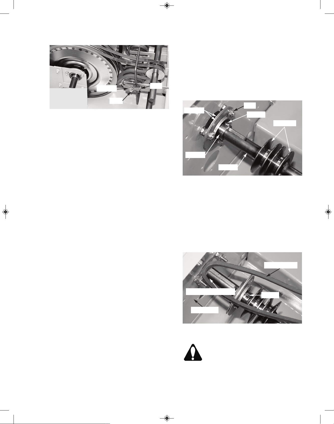
R
emove the 3/8” nut securing each #1629 Belt
Release. Remove both Belt Releases.
CLUTCH BELT REMOVAL
Remove Belts #3 and #4 from their mating CC &
JJ and DD & II Pulleys by slipping them first off
their larger II & JJ Pulleys (14” diameter) and then
off their smaller CC & DD Pulleys (3” diameter).
[Belts should be moved inwardly toward each
other and remain at center of Crawler].
HINT #1: In the removal of Belts #3 & #4
(above) you will gain extra “slack” in each Belt by
pushing forward on the Control Handles as you
slide the Belts off their respective Pulleys.
HINT #2: In the removal of Belts #2, #5, #1
and #6 (below), you will gain extra “slack” in the
Belts by pulling rearward on the Control Handles
as you slide the Belts off their respective Pulleys!
In a similar manner as above, move Belts #2 and
#5 from their mating BB & KK and EE & HH Pulleys and locate them in center of Crawler.
[Tip: Slip Belt #2 off its BB Pulley first and then
work it off its KK Pulley and then the JJ Pulley.
Similarly, slip Belt #5 off its EE Pulley first and then
work it off its HH Pulley and then the II Pulley].
Lastly, move Belts #1 and #6 from their mating AA
& LL and FF & GG Pulleys and locate them in center of Crawler. [TIP: Slip Belt #1 off AA Pulley and
around BB Pulley. Slip Belt #1 off LL Pulley and
around KK Pulley. Slip Belt #1 off BB Pulley. Now
work #1 Belt off KK Pulley and then over and off JJ
Pulley.
In a similar procedure, slip Belt #6 off FF Pulley
and around EE Pulley. Slip Belt #6 off GG Pulley
and around HH Pulley. Slip Belt #6 off EE Pulley.
Now work #6 Belt off HH Pulley and then over and
off II Pulley].
C
REATING BELT SLOT
The following steps cover the moving of the
#252B Bearing (located on the top center inside
Wall of Crawler) “inwardly” on the #1627 Upper
P
ower Shaft to create a “slot” for the belts to move
through, to be removed or new ones installed.
NOTE: Though not shown, these instructions also
apply to the likewise moving of the #252B Bearing “inwardly” on the #1643 Lower Power Shaft.
Using the proper sized “Allen Wrench” to hold the
#1807 Set Screw, use the Allen Wrench to completely remove this “set screw & nut” assembly...save for reinstallation.
Remove the three nuts securing the pair of #252A
Shells holding the #252B Bearing. Slide this Bearing & Shells assembly “inwardly” to reveal a slot
between the “end” of the #1627 Shaft and the
Body Wall (Photo below).
CAUTION: Do Not put strong forces on the now
“unsupported” left ends of the #1627
Upper & Lower Power Shafts! Shafts
were factory aligned when the Crawler
was manufactured to allow easy re-
mounting of the Bearings that you have
temporarily removed to create a “slot” on each
Shaft end.
28
#1807
#252A
#252B
Nut
#1627
#2041B
#1627 - Shaft End
#252B
#1629
Nut
Tab
#2078 - Belt
Body Wall
RS1000 Operator Manual 1.01.19.qxp_Layout 1 4/24/19 12:41 PM Page 28

29
F
F
EE
BB
A
A
CC
#2051
#
2
0
5
1
#
2
5
2
#252
#
1
6
2
9
#1629
#1617R
J
J
G
G
H
H
I
I
3
6
5
4
2
1
K
K
LL
#
1
8
0
7
#1808
3
L
L
#1627
#1643
#1632
#1854
#
2
5
2
CUTAWAY PHOTOS:
In the following Photos, some parts are dis-
torted or not shown at all. This has been done
to give clarity to the components that are being
referenced in the accompanying instructions.
RS1000 Operator Manual 1.01.19.qxp_Layout 1 4/24/19 12:41 PM Page 29

30
1
2
LL
KK
JJ
3
4
5
6
II
HH
GG
#1629
#1617L
#2051
#1629
#2051
3
4
CC
DD
#1643
#1632
#252
#252
#1807
#1807 &
#1808
#1807 &
#1808
Upper Rod
Lower Rod
AA
BB
FF
EE
#1617R
#1627
RS1000 Operator Manual 1.01.19.qxp_Layout 1 4/24/19 12:41 PM Page 30

A
t this time you can move to your left, the Belts
you wish to remove from the system. Slip them
through their respective “slot” exposed when you
moved “inwardly” the #252B Bearing Assemblies
on the #1627 Upper & #1643 Lower Power Shafts.
CLUTCH BELT INSTALLATION
EXPLANATION: The clutch belts used in your
RS1000 are special. They are the green powerrated belts that can be found at most local auto
stores. Do not confuse them with inexpensive,
fractional horsepower consumer Belts.
Your Crawler Belts are made for difficult, high
horsepower, shock load, industrial applications.
Formulated with industrial grade rubber compounds, they feature a Kevlar (bulletproof plastic)
cabled core. Molded around each Belt is a special
fabric jacket that forms the Belt’s “clutch face”.
In an hour or so of operation this fabric jacket
gains a smooth “glaze” and forms the clutch face
necessary for smooth Track Clutch engagement.
CAUTION: NEVER, NEVER, use fractional horsepower Belts in your Crawler. They are made with
light weight, “sticky compounds” that will not form
a proper glaze. This means you will not have the
SAFE clutch action mandatory for SAFE Crawler
control! In addition, fractional horsepower Belts
will break during shock loads and will leave your
clutch system out of control
!
NOTE: During the first hour or so of “breaking-in”
a new set of Belts, you potentially may hear a
squealing sound when turning. Do not be
alarmed. This is characteristic of a new set of
Belts until they have become permanently
“glazed” and gain proper smooth clutch action.
Slip the Track Clutch Belts you are installing
t
hrough the “slot” you created on the “end” of the
appropriate #1627 Upper and #1643 Lower Power
Shaft. [Belts #1, #2, #5 & #6 on the Upper Power
Shaft; Belts #3 & #4 on the Lower Power Shaft].
Slide them to the center of your Crawler.
With the (above) lubrication completed, slide the
Bearing & Shells assembly on left end of each
Upper & Lower Power Shaft back into position on
the “threaded studs” protruding from crawler wall.
Replace original nuts over Bearing threaded studs
and tighten.
Take original #1807 Set Screw and thread it into
its original threaded hole of bearing...rotate the
#1627 (or #1643) Shaft within the bearing to align
the end of the #1807 Set Screw with its mating “V”
slot in shaft’s end.
Use your Allen Wrench to tighten the Set Screw
...make sure it’s end hits the “V” slot “dead cen-
31
#1807
#252A
#252B
Nut
#1627
#2041B
#2078 - Belt
Body Wall
#1627 - Shaft End
#252B
#1627
“V” Slot
#1807
SPECIAL NOTE: It’s mandatory that you
keep “left ends” of the Upper & Lower Power
Shafts properly lubricated. A film of grease or
anti-sieze must totally cover the Shaft ends
from the #2041B Pulley to the “left end” of
each Shaft! As you grease the Shaft, work the
#252B Bearing back and forth to make sure
it’s completely coated! To ignore this procedure may make it impossible to slide the Bearing to change Belts in the future, which would
require serious drive train rebuilding to correct
the problem (see Photo below).
Lubr
icate
RS1000 Operator Manual 1.01.19.qxp_Layout 1 4/24/19 12:41 PM Page 31
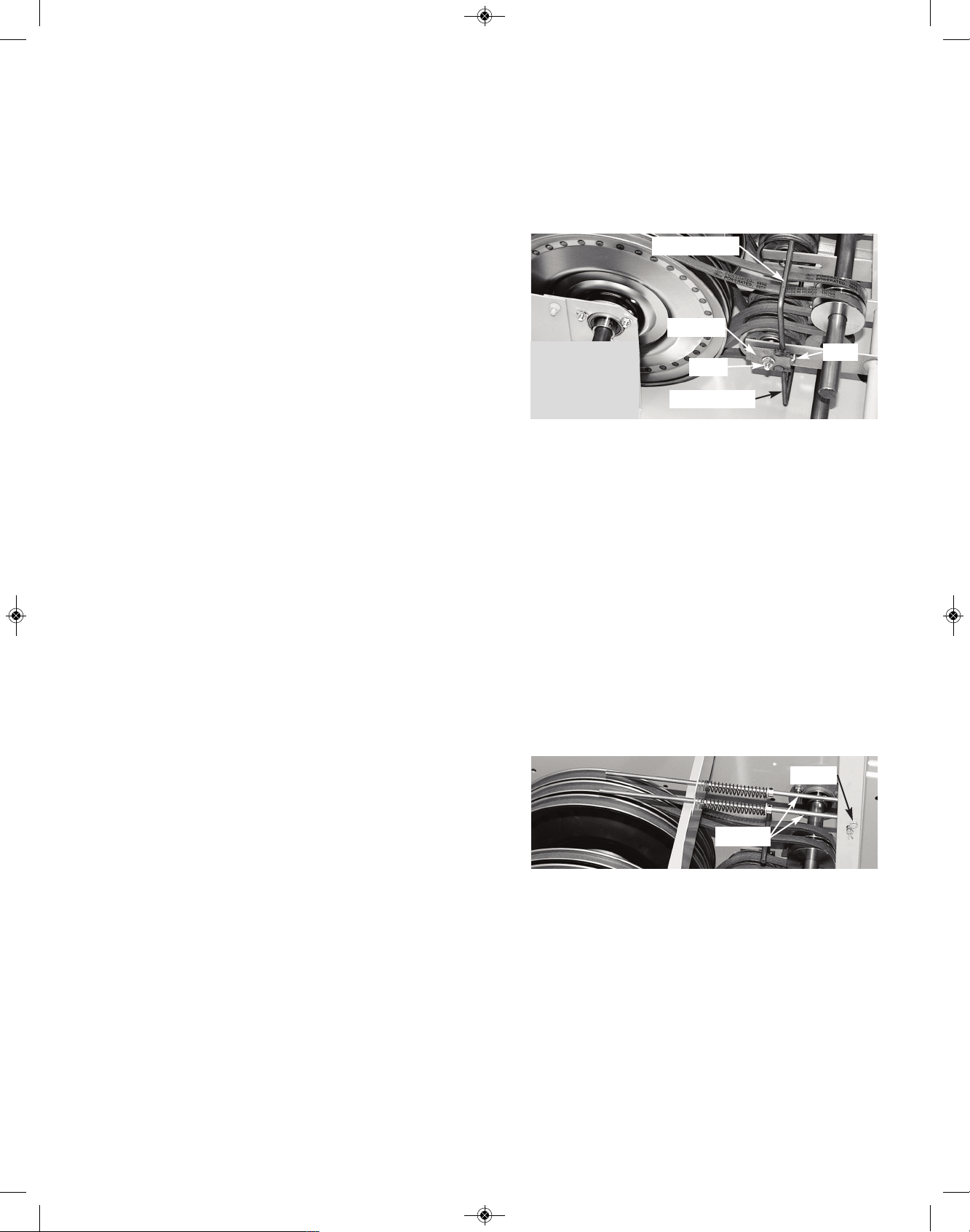
t
er”. (Use this procedure for both the Upper &
Lower Power Shafts). When you are done the
bearing end of shaft should look like photo (previous page).
A
rrange the Belts and note that the two Belts on
the Lower Power Shaft will be Belts #3 & #4 and
will remain in the center (to be installed last). Locate Belts #1 & #2 (on Upper Power Shaft) just to
the right of the #3 Belt. Locate the remaining Belts
#5 & #6 (on Upper Power Shaft) just to the left of
the #4 Belt.
NOTE: No single Belt can ever be around
both the Upper and Lower Power Shafts
at any one time!
Slip rearward end of Belt #1 first over JJ Pulley
and then around KK Pulley. Now slip forward end
of Belt #1 over BB Pulley and then around AA Pulley. Lastly, slip rearward end of Belt #1 around LL
Pulley. [TIP: Pulling back on Track Clutch Control
Handles during this and following procedures will
give Belts more slack and ease installation].
In a method similar to step above, slip
rearward end of Belt #6 first over II Pulley
and then around HH Pulley. Now slip for
ward end of Belt #6 over EE Pulley and
then around FF Pulley. Lastly, slip rear
ward end of Belt #6 around GG Pulley.
Slip rearward end of Belt #2 first over JJ Pulley
and then around KK Pulley. Now slip forward end
of Belt #2 around BB Pulley.
In a method similar to step above, slip
rearward end of Belt #5 first over II Pulley
and then around HH Pulley. Now slip for
ward end of Belt #5 around EE Pulley.
Slip forward end of Belt #3 around CC Pulley and
then slip rearward end of Belt #3 around JJ Pulley.
[TIP: Pushing forward on Track Clutch Control
Handles during this step and the next, will give
Belts more slack and ease installation].
In a method similar to step above, first slip
forward end of Belt #4 around DD Pulley
and then slip rearward end of Belt #4
around II Pulley.
At this point, each Belt should be in place and
around its respective “pair” of Pulleys. Belts #1,
#
2, #5, and #6 should be resting on “top” of their
respective #2051 Flat Idler Pulleys. Belts #3 and
#4 should rest “below” their respective #2051 Flat
Idler Pulleys. Check photos and make sure each
Belt follows its proper path from Pulley to Pulley
a
nd that it rests against (and between the raised
“flanges”) of its respective #2051 Idler Pulley.
Replace both #1629 Belt Releases using original
nuts to secure. NOTE: “TAB” goes forward on
both sides.
Make sure Belt Release’s Lower and Upper Rods
are always on the “outside” of the Belts ...NEVER
inside!
Belt Release’s Upper Rods should be on top and
over the outside face of its pair of Belts (#1 & #2
on the right; #5 & #6 on the left).
Belt Release’s Lower Rods should be below and
under the outside face of it’s Belts (#3 on the right;
#4 on the left).
Replace #1638 Spring Rods to the #1617 & #1632
Left & Right Clutch Handle Assemblies. Secure in
place with #910 Hitch Pins.
32
#1629
Nut
Tab
Upper Rod
Lower Rod
#1638
#910
RS1000 Operator Manual 1.01.19.qxp_Layout 1 4/24/19 12:41 PM Page 32

CLUTCH BELT ADJUSTMENT
Your Track Clutch Belts are adjusted as two
“matched sets” of three belts each. One matched
set (Belts #1, #2 and #3) for the Right Track and
t
he other matched set (Belts #6, #5 and #4) for the
Left Track.
Begin your procedure by parking your Crawler on
an open, firm, level surface. Shut off Engine, engage your Parking Brake Lever and dismount.
Raise Hood, fully rotate it forward, remove #1688
Seat Pin. Then remove the #933A Seat & #1674
Mounting Bracket, #1625 Arm Rests, and #1608
Rear Cover. NOTE: Be sure to disconnect the
“mating” #1829 and #1825 Seat Wires at their
common Plug.
Determine if your Belts are in proper adjustment
by measuring the distance of travel (forward to reverse) of each Control Handle. They should travel
approximately 4-1/2” when measured at the “furthest end” of their Control Handles. If it is OK,
close up your Crawler; Don’t forget to reconnect
#1824 & 1825 Wires & Plugs!
If not, follow the procedure below:
Remove the 3/8” Nut securing each #1629 Belt
Release...remove both Belt Releases.
Loosen the 2nd 3/8” Nut holding each of the
#2051 three Idler Pulley assemblies in place on
their respective #1617R & 1617L Right & Left
Control Handle Assemblies. Loosen, so each Pulley Assembly (containing three #2051 Idler Pulleys each) can slide forward and rearward in its
respective Yoke.
Position each Pulley Assembly (forward or rearward) such that it’s
respective Control Handle
can “rotate” a total distance of 4-1/2” (when
measured at the “furthest
end” of Control Handle).
Complete this adjustment
for both Right and Left
Pulley Assemblies. When
satisfied with adjustment of both Pulley Assemblies, tighten the Locknut you loosened above.
NOTE: as you tighten
the (above) Locknuts you
must keep the Pulley Assemblies at a 90 degree
angle to the Yokes in
each Control Handle assembly. Using a “homemade” sheet of metal,
wood, etc. (approximately
3-1/4” x 6”) as a “guide” is
a big help in holding this
angle!
33
(3) #2051
#1617R
Yoke
#1629
Nut
Tab
4-1/2”
Fully Forward
Fully Reverse
Control
Handle
90 Degrees
#1617R
#2051
Yoke
Guide
#1625
#933A
#1608
#1688
#1674
On
Off
#1829
#1825
Plug
2nd Nut
RS1000 Operator Manual 1.01.19.qxp_Layout 1 4/24/19 12:41 PM Page 33

Replace both #1629 Belt Releases and secure
each with original Locknuts. NOTE: Assemble
such that “Tab” on both Belt Releases is “forward”
of their Locknuts!.
Make sure Belt Release’s Lower and Upper Rods
are always on the “outside” of the Belts ...NEVER
inside! Belt Release’s Upper Rods should be on
top and over the outside face of its pair of Belts
(#1 & #2 on the right; #5 & #6 on the left).
Belt Release’s Lower Rods should be below and
under the outside face of it’s Belts (#3 on the right;
#4 on the left).
At this time “close-up” your Crawler following instructions for Seat & Rear Cover Assembly section (below). Don’t forget to reconnect #1829 &
1825 Plugs!
34
#1629
Nut
Tab
Upper Rod
Lower Rod
RS1000 Operator Manual 1.01.19.qxp_Layout 1 4/24/19 12:41 PM Page 34
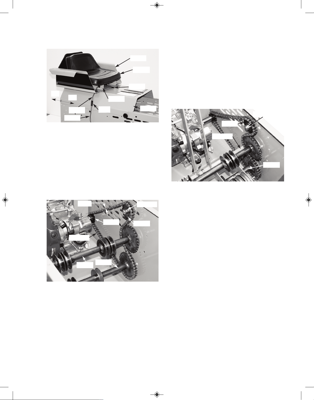
ENGINE DRIVE
CHAIN (if equipped)
Begin your procedure by parking your Crawler
on an open, firm, level surface. Shut off Engine,
engage your Parking Brake Lever and dismount.
Raise Hood and rotate it fully forward, remove the
#1688 Seat Pin. Then remove the #933A Seat &
#1674 Mounting Bracket, #1625 Arm Rests, and
#1608 Rear Cover. NOTE: Be sure to disconnect
the “mating” #1829 and #1825 Seat Wires at their
common Plug.
Check your #1804A Engine Drive Chain. Pull up
on the recoil starter rope to “tension” the Chain
and create slack (sag) in the Chain portion going
from #1801 Engine Sprocket to #1689 Idler
Sprocket.
This “sag” should be approximately 1/4” to 1/2”.
Though quieter operation results from a looser
Chain, it does present the rare chance for the
Chain to jump off it’s sprockets.
C
HAIN ADJUSTMENT
To loosen or tighten the Chain, loosen the Locknut securing the #1689 Idler Sprocket and slide
the Idler Sprocket assembly forward for Chain
l
oosening, and rearward for tightening.
NOTE: When tightening the Idler in position, hold
the Locknut with one wrench, but “tighten” it with
a second wrench on the bolt’s head outside the
Crawler’s Body...this technique helps to keep the
Idler Assembly from “creeping out of position” as
you “securely” tighten it’s bolt.
CHAIN REPLACEMENT
Loosen the Locknut securing the #1689 Idler
Sprocket and slide this assembly forward. “Work”
the now loose Chain around so the Connector
Link is convenient to work on. Remove the Chain
Connector Clip and remove the Connector from
the Chain. Remove the Chain.
The new Chain is shipped from the factory
assembled...the Connector is already attached
and the Chain is a continuous loop. You have two
ways to install it: (Note: In some designs, you may
have to move the engine!)
1) You may install it much the same way a
Belt is installed...through the “slot” in left end of
#1643 Lower Power Shaft. You also need to pass
it around the right end of #1617C tube of the
#1617R Right Control Handle Assembly.
2) Alternately you can disassemble the
Chain’s Connector Link and open the Chain and
loop it around it’s various sprockets. Then join the
Chain’s ends with it’s Connector Link and secure
with Connector Clip.
The easiest is Step (2) above. It’s a little tricky because you have to compress “O” rings while you
put on its “flat spring” Connector Clip. Practice with
the Chain you took off; it will give you a chance to
practice and build confidence.
35
#1801
#1689
Locknut
#1804A
#1627
“Sag”
#1643
#1643
#1617C
Locknut
#1689
#1625
#933A
#1608
#1688
#1674
On
Off
#1829
#1825
Plug
RS1000 Operator Manual 1.01.19.qxp_Layout 1 4/24/19 12:42 PM Page 35
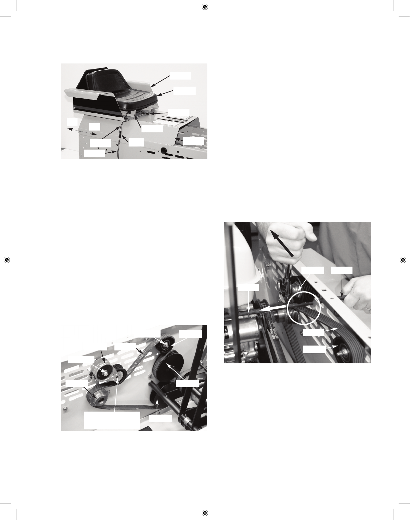
ENGINE DRIVE
MICRO-V BELT (if equipped)
To access the #4356 Micro-V Engine Drive Belt,
begin your procedure by parking your Crawler
on an open, firm, level surface. Shut off Engine,
engage your Parking Brake Lever and dismount.
Turn the 2 black handles (not shown) slightly
counter-clockwise to loosen hood. Raise and rotate hood fully forward. Remove the #1688 Seat
Pin. Then remove the #933A Seat & #1674
Mounting Bracket, #1625 Arm Rests, and #1608
Rear Cover. Remove any additonal cross braces
that will aloow easy access to this area. NOTE:
Be sure to disconnect the “mating” #1829 and
#1825 Seat Wires at their common Plug. See pic-
ture above.
Check the condition of your #4356 Micro-V Engine
Drive Belt per section 6-LUBRICATION & PERIODIC SERVICE.
MICRO-V BELT ADJUSTMENT
If your RS1000, is equipped with a #4356 MicroV Engine Drive Belt, you have an auto belt tensioner system. The #4341 auto tensioner puts the
c
orrect amount of tension on your drive belt at all
times. No need to make any drive belt adjustments!
MICRO-V BELT REMOVAL & REPLACEMENT
If your #4356 Micro-V Drive Belt is broken, you
should just be able to pull it out easily from the engine area. If it is frayed or just badly worn, please
follow these steps for removal and installation of
new #4356 Micro-V Drive Belt.
1. Remove tension from the #4356 Micro-V belt
by inserting a 3/8” drive socket ratchet in the
square hole in the #4341 auto tensioner. (See pic-
ture in opposite column for access area).
While pulling towards the front of the tractor, insert a #1521 Tension Bar through the oval slot in
the body, under the #4341 auto tensioner, on top
of the #4356 Micro-V Belt and onto the engine.
This allows you to keep the #4341 auto tensioner
from putting tension on the #4356 Micro-V Belt.
At this time, your hands should be free and the
#4341 auto tensioner should not be
putting tension on the #4356 Micro-V Belt, just the #1521
Tension Bar.
2. From inside of machine: hold the idler locknut
with wrench. From outside of machine: use a
wrench, a socket ratchet or cordless socket
ratchet to loosen the coresponding bolt. (Do not
remove!) Idler assembly should slide forward in
the body wall slot. Tension should fully be removed from the #4356 Micro-V-Belt at this time.
See pictures on the next page.
36
#1625
#933A
#1608
#1688
#1674
On
Off
#1829
#1825
Plug
#4356
#4345
#4344Locknut
#4355
#4346
#4341
Locknut
3/8” drive socket
access area
#4344
#4356
#1521
#1521
#4341
RS1000 Operator Manual 1.01.19.qxp_Layout 1 4/24/19 12:42 PM Page 36

3. For the quickest removal of the #4356 Micro-V
Belt: cut it in half with a side cutters or scissors.
Note: Be careful to not knick or scratch other
surrounding components. Especially engine
wires!
4. Installation of new #4356 Micro-V Drive Belt.
You may install it much the same way a rear
#2078 Clutch Belt is installed...through the “slot” in
left end of #1643/#4355 Lower Power Shaft. You
also need to pass it around the right end of
#1617C tube of the #1617R Right Control Handle
Assembly. For this part of the install, (Please ref-
erence pages 28-32 in Section 7). Speak with a
Struck tech for additional help. There may be
other ways to do this procedure.
5. Once you’ve looped the new #4356 Micro-V
Belt around the #1643/#4355 Lower Power Shaft,
you can loop it between the #4345 Micro-V Engine Pulley and body wall as shown in the picture
at the top of the next column. Note: It is possible
to loosen the #4345 Micro-V Engine Pulley and
push it towards the engine, but you should not
need to do this in most applications.
6
. (Optional) If you decided to loosen the engine
pulley and push it toward the engine, you’ll need
to loosen the (2) set screws on the engine pulley
first, then slide the #4356 Micro-V Belt throgh,
then re-align the #4345 Micro-V Engine Pulley. As
s
hown in the picture below, from the body wall to
the 3rd V groove center should measure 7/8”.
Make sure to re-apply red loc-tite back to both set
screws (just on the threads) and tighten fully with
allen wrench.
7. Using the picture below as a reference, route
the #4356 Micro-V Belt along the pulleys. Making
sure the Micro-V Belt is seated properly in the idler
pulley grooves. Note: The #4356 Micro-V Belt
should already be looped around the
#1643/4355 Lower Power Shaft from step 4.
Your #4356 Micro-V Belt should now be properly
routed and seated and look like the picture on the
top left of the next page. The #4356 Micro-V Belt
should be loose, with the #1521 Tension Bar still
holding the tension away from the #4356 Micro-V
Belt, by holding the #4341 Auto Tensioner away
from the Micro-V Belt.
37
#4344
Locknut
#4344
Locknut
Loose #4356
#4356
Body
Wall
#4345
7/8”
#4356
#4345
Along
front
edge
of
#4346
#4341
Around rear &
top of #4344
Around bottom
& rear of #4355
Around bottom
of #4341
RS1000 Operator Manual 1.01.19.qxp_Layout 1 4/24/19 12:42 PM Page 37

8. To tighten the Micro-V Belt, hold the locknut
with one wrench and pull rearward at the same
time. (Pull as hard as possible). From the outside of the machine: use a wrench or socket
ratchet to tighten the coresponding bolt. The Idler
assembly should not slide forward in the body wall
slot. See picture below.
9. Add proper tension to the #4356 Micro-V belt
by inserting a 3/8” drive socket ratchet in the
square hole in the #4341 auto tensioner. While
pushing towards the rear of the tractor, carefully
slide the #1521 Tension Bar out of the body of the
RS1000, being careful of engine wires, etc. (See
picture at the top of the next column).
10. At this time double check your work. Take a
look at the #4356 Micro-V belt to make sure it is
aligned and seated properly, and also that any
loosend set screws have had red-loctite added to
them and fully tightened. Your Micro-V Belt assembly should look like the picture below.
11. Run your machine to test that it is working
properly. Contact Tech Support with any questions
on this Micro-V removal or replacement.
38
#4344
Locknut
#4344
Locknut
Loose #4356
#1521
#4341
#4344
#4356
#1521
#1521
#4341
RS1000 Operator Manual 1.01.19.qxp_Layout 1 4/24/19 12:42 PM Page 38

STEEL TRACK MAINTENANCE
(if equipped)
B
efore attempting to complete any part of this
T
rack Maintenance section, it is recommended
that you read all four parts (Steel Track Removal,
Steel Track Replacement, Steel Track Tensioning
and Maintenance Steel Track Tensioning ) to provide background on how the total Steel Track System is adjusted and maintained.
Below are a series of drawings and photos to aid
you in parts identification as you read the following
procedures. For clarity, only the parts described in
the instructions are included in the drawings and
photos. In some cases, to lessen confusion, certain parts do not appear in all drawings and photos.
CAUTION: When working with the
Tracks, you will be dealing with some
significant weight and lifting situations.
Though the Crawler can be successfully
“blocked up” off the ground and the Tracks removed and replaced by a single person, it’s advisable to have an able-bodied “helper” available
for both assistance and safety.
Begin any Track Maintenance procedure by
checking that your Track System is relatively clean
and free of debris...a high-pressure wash job is an
excellent idea. In addition, drive your Crawler
through a “clean area” to work out debris that may
have lodged between Track Sprocket teeth or in
the Track’s Chain Links. Park your Crawler on a
firm level surface, shut off engine, set Parking
Brake and dismount.
STEEL TRACK REMOVAL
From below, support body of Crawler so its Tracks
clear the ground by approximately 2” and are free
t
o rotate...release Brake at this time.
Use solid blocking, place it under the Crawler’s
Body per “Safe Blocking Diagram” on front page
of this Manual. It will give the Crawler the greatest
support left to right and front to rear. [When locating your blocking, analyze the total weight and
balance of the Crawler as it will change as the
Tracks are removed and then replaced!
NOTE: As you work with the Tracks, realize that
the more you can support the “lower strand” of
each Track and keep it flat and close to its original
operating level, the more slack you will have in the
“upper strand” of the Track to work with!
1. Loosen and remove the 1/2” Jam Nut from the
threaded end of each #1810 Tension Bolt. Then
loosen the Locknut until it is “flush” with the end
of the #1810 carriage bolt. Do this to both sides.
2. From “outside” the Crawler’s body, fully loosen
(but do not remove) the five nuts on each (Left &
Right) #1611 Front Axle Plate. Slide #2065 Axle
fully rearward.
3. With gloved hands, begin to rotate the Track forward. [TIP: As you rotate the Track, you may want
to move the Track Clutch Controls back and forth
to relieve any “drag” from the Track Clutch Belts].
39
#1810
(5)1/2” Washers
#1689
#1885
#1806
Jam
Nut
Locknut
#1691
#1611
#2065
#2065
RS1000 Operator Manual 1.01.19.qxp_Layout 1 4/24/19 12:42 PM Page 39

4
. As the Track is rotated forward, work the forward
end of the Track outward. Stop working the Track
outward when the Track’s Inner Chain is centered
between the Inner & Outer Sprockets of the Front
Idler...see drawing below.
5. In a similar manner, rotate the Track rearward
making sure that the Track’s Inner Chain remains
between the Inner & Outer Sprockets on the Front
Idler. This time work the rearward end of the Track
over both the Inner & Outer Sprockets of the Rear
Drive...see drawing below.
6. Pulling forward on the Track will allow you to
now loop the Track off the remaining Outer
Sprocket on the Front Idler allowing complete
Track removal.
STEEL TRACK REPLACEMENT
Before replacing a Track, it’s wise to thoroughly
clean it of all debris...a pressure wash job is a
good idea.
1. Slip the rearward end of Track around the Inner
& Outer Sprockets of the Rear Drive engaging the
Track’s Inner Chain between the Inner & Outer
Sprockets of the Rear Drive.
2. Loop the forward end of the Track around the
Inner & Outer Sprockets of Front Idler engaging
the Track’s Inner Chain between the Inner & Outer
Sprockets of the Front Idler.
3
. The Track’s Inner Chain should now be located
between the Inner & Outer Sprockets of the Front
Idler and Rear Drive.
4. Begin rotating the Track rearward. As the Track
rotates rearward work the Track inward until the
Track’s Inner & Outer Chains align and engage the
teeth of their mating Inner & Outer Sprockets of
the Rear Drive.
5. Rotate Track forward and work the Track inward
until the Track’s Inner & Outer Chains align and
engage the teeth of their mating Inner & Outer
Sprockets on the Front Idler.
40
RS1000 Operator Manual 1.01.19.qxp_Layout 1 4/24/19 12:42 PM Page 40

STEEL TRACK TENSIONING
1
. Over protruding “threaded end” of each #1810
Tension Bolt (on each side of Crawler body) slip
on, in the following order: five 1/2” Washers,
#1689 Washer, #1885 Tube, #1806 Spring, and
one #1689 Washer. Secure with Locknut.
2. By rotating clockwise the Locknut you mounted
to end of each #1810 Tension Bolt, draw the Locknut and associated #1689 Washer (on each Tension Bolt’s end) against its respective #1806
Spring such that each Spring is compressed to a
total length of 1-3/8” (measured from inside
Washer to Washer).
NOTE: Tighten the pair of #1806 Springs 1/4” at a
time. Tighten the left Spring 1/4”, then stop and go
to the right Spring and tighten it 1/4”. Work back
and forth from left side #1806 Spring to right side
#1806 Spring, 1/4” at a time, until each Spring is
1-3/8” in total length. [Measure Spring length
only...do not include the # 1689 Washers in your
measurement].
3. Using a “blunt-nose punch” and hammer, push
the #1611 Front Axle Plate (located on both sides
of Crawler Body) rearward till it hits a solid stop
(approximately 3/16”). NOTE: In the work accomplished in steps above, this Plate may have already moved rearward. To check, push Plate
forward from the rear, then push it back the required 3/16” distance.
NOTE: This is a simple adjustment, but it’s
p
roper execution results in extremely stable
Track performance in the future!
4
. At this time, slowly and safely remove all sup-
port blocking from underneath your Crawler so
that it rests firmly on only its Tracks.
5. Remount and safely restart your Crawler. Drive
it approximately 25 feet forward and then go in reverse, back to your starting point. Shut off the engine, set Parking Brake and dismount. Check the
overall length of your #1806 Springs for any
changes in length. Readjust to proper 1-3/8” overall length if necessary.
6. When satisfied, mount a Jam Nut to remaining
ends of each #1810 Tension Bolt. Hold each Locknut with a “thin profile” 3/4” open end wrench, and
tighten each Jam Nut with a 3/4” box wrench
...tighten securely!
7. Tighten the five nuts securing Left & Right
#1611 Front Axle Plates... check Photo at lower
left.
41
Push #1611 fully to rear,
approximately 3/16”!
#1611
1-3/8”
Jam
Nut
Locknut
#2065
#1810
#1689
1-3/8”
Jam
Nut
Locknut
(5) 1/2” Washers
#1806
#2065
#1810
RS1000 Operator Manual 1.01.19.qxp_Layout 1 4/24/19 12:42 PM Page 41

MAINTENANCE STEEL TRACK
TENSIONING
Begin by checking the overall length of the #1806
S
pring on each side of Crawler. Both Springs
s
hould be compressed to an overall length of 1-
3/8”. [The length measured is only the Spring; do
not include the #1689 Washers in your measurement!]
If your Springs have lost this 1-3/8” dimension, or
you have just replaced a #1806 Spring or broken
#1810 Tension Bolt, follow this procedure:
1. From “outside” the Crawler’s Body, fully loosen
(but do not remove) the five nuts on each (Left &
Right) #1611 Front Axle Plate.
2. Remove the Jam Nut on the threaded end of
each #1810 Tension Bolt. Rotate (clockwise or
counter-clockwise) the Locknut on each #1810
Tension Bolt so that its respective #1689 Washer
(next to #1806 Spring) is pushed forward (or released rearward) thereby setting its respective
#1806 Spring to a final length of 1-3/8”.
3. [Work back and forth, from left side to right side
of Crawler, tightening each Spring 1/4” at a time
until you have achieved a 1-3/8” overall length for
both Springs. [Measure Spring length only].
4. Using a “blunt-nose punch” and hammer, push
the #1611 Front Axle Plate (located on both sides
of Crawler Body) rearward till it hits a solid stop
(approximately 3/16”). NOTE: in the work done in
steps above, this Plate may have already moved
rearward. To check, push Plate forward from the
rear, then push it back the required 3/16” distance.
Tighten the five nuts securing left & right #1611
Front Axle Plates.
NOTE: This is a simple adjustment, but it’s
proper execution results in extremely stable
Track performance in the future!
5. Remount and safely restart your Crawler. Drive
it approximately 25 feet forward and then go in reverse, back to your starting point. Shut off the engine, set Parking Brake and dismount. Check the
overall length of your #1806 Springs for any
changes in length. Readjust to proper 1-3/8” overall length if necessary.
6. When satisfied, mount a Jam Nut to remaining
ends of each #1810 Tension Bolt. Hold each Locknut with a “thin profile” 3/4” open end wrench, and
tighten each Jam Nut with a 3/4” box wrench
7. Tighten the five nuts securing Left & Right
#1611 Front Axle Plates.
42
Push #1611 fully to rear,
approximately 3/16”!
#1611
1-3/8”
Jam
Nut
Locknut
#2065
#1810
RS1000 Operator Manual 1.01.19.qxp_Layout 1 4/24/19 12:42 PM Page 42

RUBBER TRACK MAINTENANCE
(if equipped)
B
efore attempting to complete any part of this
R
ubber Track Maintenance section, it is recommended that you read all four parts (Rubber Track
Removal, Rubber Track Replacement, Rubber
Track Tensioning and Maintenance Rubber Track
Tensioning ) to provide background on how the
total Rubber Track System is adjusted and maintained.
Below is a photo to aid you in parts identification
as you read the following procedures. For clarity,
only the parts described in the instructions are included in the drawings and photos. In some
cases, to lessen confusion, certain parts do not
appear in the following photos.
CAUTION: When working with the Rubber Tracks, you will be dealing with
some significant weight and lifting situ-
ations. Though the Crawler can be successfully “blocked up” off the ground and the
Rubber Tracks removed and replaced by a single
person, it’s advisable to have an able-bodied
“helper” available for both assistance and safety.
Begin any Rubber Track Maintenance procedure
by checking that your Rubber Track System is relatively clean and free of debris...a high-pressure
wash job is an excellent idea. In addition, drive
your Crawler through a “clean area” to work out
debris that may have lodged between Track
Sprocket teeth. Park your Crawler on a firm level
surface, shut off engine, set Parking Brake and
dismount.
RUBBER TRACK REMOVAL
From below, support body of Crawler so the
Tracks clear the ground by approximately 2” and
a
re free to rotate...release Brake at this time.
Use solid blocking, place it under the Crawler’s
Body per “Safe Blocking Diagram” in front section of this Manual. It will give the Crawler the
greatest support left to right and front to rear.
[When locating your blocking, analyze the total
weight and balance of the Crawler as it will
change as the Tracks are removed and then replaced!
NOTE: As you work with the Tracks, realize that
the more you can support the “lower strand” of
each Track and keep it flat and close to its original
operating level, the more slack you will have in the
“upper strand” of the Track to work with!
1. Loosen and remove the 1/2” Jam Nut from the
threaded end of each #1810 Tension Bolt. Then
loosen the Locknut until it is “flush” with the end
of the #1810 carriage bolt. Do this to both sides
of the crawler, left & right.
2. From “outside” of the Crawler’s body, fully
loosen (but do not remove) the five nuts on each
(Left & Right) #1611 Front Axle Plate. Slide #2065
Axle fully rearward. See picture on next page.
43
Jam
Nut
Locknut #1689 #1810
(5)1/2” Washers#1885#1806
Jam
Nut
#1810
#2065
Rear Drive
Sprocket
Front Idler
Sprocket
“Upper Strand”
“Lower Strand”
Front
Idler
Sprocket
“Center Idlers”
RS1000 Operator Manual 1.01.19.qxp_Layout 1 4/24/19 12:42 PM Page 43

HINT: With a mallet, gently pound rearward on the
front idler sprocket tooth. Do the same to the other
side as well. Work back and forth until both left
and right front idler sprockets are all the way rearward. Once fully loosened, your tracks should
look similar to the picture shown below. Center
idlers not shown.
3. With gloved hands, begin to rotate the Track
forward. [TIP: As you rotate the Track, you may
want to move the Track Clutch Controls back and
forth to relieve any “drag” from the Track Clutch
Belts].
NOTE: As you work with the Tracks, realize that
the more you can support the “lower strand” of
each Track and keep it flat and close to its original operating level, the more slack you will have in
the “upper strand” of the Track to work with!
4. Pulling rearward on the Track will allow you to
now loop the Track off the Rear Drive Sprocket allowing complete Track removal. See picture on
the top of next column.
Once the track is removed, your crawler track system should now look like the following picture.
Note: Center idlers not shown for clarity.
RUBBER TRACK REPLACEMENT
Before replacing a Track, it’s wise to thoroughly
clean it of all debris...a pressure wash job is a
good idea. Note: You can start with the front
idler instead of the rear drive. We started with
the rear drive in the steps that follow.
1. Slip the rearward end of Track around the
Sprocket of the Rear Drive. Rotate the rubber
track slightly to mate up the rear drive sprocket
teeth with the mating sprocket holes in the track.
Once lined up, gently pound forward on the
sprocket tooth. The sprocket teeth should be
“seated” in the track. See picture on next page.
44
#1611
#2065
(
4) Nuts
(1) Nut
Pound Rearward
Front
Idler
Sprocket
“Lower Strand”
“Upper Strand”
RS1000 Operator Manual 1.01.19.qxp_Layout 1 4/24/19 12:42 PM Page 44

2. Once happy with the proper “seating”, make
sure the front idler sprocket is all the way rearward before attempting to attach track onto
front idler sprocket. See Rubber Track Removal
Section for additional details.
3. Once happy with the proper “seating” of the rear
drive track sprocket, and that your front idler is all
the way rearward, loop the forward end of the
Track around the Front Idler Sprocket.
4. The front idler and/or tracks may have to be rotated to “seat” the front idler sprocket teeth correctly into the track openings.
Y
our front idler and rear drive sprockets should be
properly “seated” into the track openings. If you
have questions please call the factory and ask to
speak with a struck technician regarding any additional questions or concerns that you may have.
O
nce happy with the track “seating”, please repeat
these steps for the other side of the crawler.
Tracks properly “seated”, but still loose,
shown below.
RUBBER TRACK TENSIONING
1. Loosen and remove the 1/2” Jam Nut from the
threaded end of each #1810 Tension Bolt. Do this
to both sides of the crawler, left & right.
2. Tighten the Locknut on end of each #1810 Ten-
sion Bolt, until 1/2” of space is between the
“front edge” of the #2065 Axle and the “rear
edge” of the expander plate. See picture
above.
NOTE: Tighten the left side 1/4” at a time, then
stop and go to the right side and tighten it 1/4”.
45
Locknut
#1810
Pound Forward
Proper Seating
#1611
#2065
(4) Nuts
(1) Nut
Pound Rearward
Front
Idler
Sprocket
Proper Seating
Jam
Nut
#2065
Jam
Nut
Locknut #1689 #1810
(5)1/2” Washers
#1885#1806
1/2” Washers
Expander
Plate
Approx. 1/2”
potruding
RS1000 Operator Manual 1.01.19.qxp_Layout 1 4/24/19 12:42 PM Page 45

3
. Work back and forth from left side to right side,
1/4” at a time, until 1/2” of space is between the
“front edge” of the #2065 Axle and the “rear
edge” of the expander plate.
4. Using a “blunt-nose punch” and hammer, push
the #1611 Front Axle Plate (located on both sides
of Crawler Body) forward untill it hits a solid stop.
NOTE: In the work accomplished in steps above,
these plates may have already moved forward. To
check, push plates forward from the rear.
NOTE: This is a simple adjustment, but this
proper execution, along with the center idler
system, results in extremely stable Track performance in the future!
5. At this time, slowly and safely remove all sup-
port blocking from underneath your Crawler so
that it rests firmly on only its Tracks.
6. Remount and safely restart your Crawler. Drive
it approximately 10 feet forward and then go in reverse, back to your starting point. Shut off the engine, set Parking Brake and dismount. Check that
1/2” of space is between the “front edge” of
the #2065 Axle and the “rear edge” of the ex-
p
ander plate. Re-adjust if necessary.
7. When satisfied, mount a Jam Nut to remaining
ends of each #1810 Tension Bolts. Hold each
Locknut with a “thin profile” 3/4” open end wrench,
a
nd tighten each Jam Nut with a 3/4” box wrench
...tighten securely!
8. Tighten the five nuts securing Left
& Right
#1611 Front Axle Plates... see photo below.
Congratulations! Your rubber track tensioning procedure is complete. Your track system should look
like the photo below.
46
Front
Idler
Sprocket
#1611
(5) Nuts
#1611
Locknut
#1810
Jam
Nut
#2065
1/2” Washers
Expander
Plate
Approx. 1/2”
potruding
Locknut
#1810
Jam
Nut
#2065
1/2” Washers
Expander
Plate
Approx. 1/2”
potruding
RS1000 Operator Manual 1.01.19.qxp_Layout 1 4/24/19 12:43 PM Page 46

MAINTENANCE RUBBER TRACK
TENSIONING
Begin by checking that 1/2” of space is between
t
he “front edge” of the #2065 Axle and the
“
rear edge” of the expander plate.
If your tracks have become de-railed, or your
#2065 axles have lost this dimension, or you have
just replaced a #1806 Spring or broken #1810
Tension Bolt, follow this procedure:
1. From “outside” the Crawler’s Body, fully loosen
(but do not remove) the five nuts on each (Left &
Right) #1611 Front Axle Plate.
2. Remove the Jam Nut on the threaded end of
each #1810 Tension Bolt. See photo at top of
page. Rotate (clockwise or counter-clockwise) the
Locknut on each #1810 Tension Bolt so that its respective #1689 Washer (next to #1806 Spring) is
pushed forward (or released rearward).
3. Work back and forth from left side to right side,
1/4” at a time, until 1/2” of space is between the
“front edge” of the #2065 Axle and the “rear
edge” of the expander plate.
4. Using a “blunt-nose punch” and hammer, push
the #1611 Front Axle Plate (located on both sides
of Crawler Body) forward untill it hits a solid stop.
NOTE: In the work accomplished in steps above,
these plates may have already moved forward. To
check, push plates forward from the rear.
NOTE: This is a simple adjustment, but it’s
proper execution results in extremely stable
Track performance in the future!
5. Remount and safely restart your Crawler. Drive
it approximately 10 feet forward and then go in reverse, back to your starting point. Shut off the engine, set Parking Brake and dismount. Check
your tension. Approx. 1/2” of space is between
the “front edge” of the #2065 Axle and the
“rear edge” of the expander plate. Re-adjust if
necessary.
6. When satisfied, mount a Jam Nut to remaining
ends of each #1810 Tension Bolt. Hold each Locknut with a “thin profile” 3/4” open end wrench, and
tighten each Jam Nut with a 3/4” box wrench
7. Tighten the five nuts securing Left & Right
#1611 Front Axle Plates.
47
(5) Nuts
#1611
(5) Nuts
#1611
Front
Idler
Sprocket
#1611
Locknut
#1810
Jam
Nut
#2065
1/2” Washers
Expander
Plate
Approx. 1/2”
potruding
RS1000 Operator Manual 1.01.19.qxp_Layout 1 4/24/19 12:43 PM Page 47

SWITCHING OUT
STEEL TRACK SYSTEM TO
RUBBER TRACK SYSTEM
Below are a series of drawings and photos to aid
you in parts identification as you read the following
procedures. For clarity, only the parts described in
the instructions are included in the drawings and
photos. In some cases, to lessen confusion,
certain parts do not appear in all drawings and
photos.
CAUTION: When working with the
Tracks, you will be dealing with some
significant weight and lifting situations.
Though the Crawler can be successfully “blocked up” off the ground and the Tracks removed and replaced by a single person, it’s
advisable to have an able-bodied “helper” available for both assistance and safety.
Begin any Track Removal procedure by checking
that your Track System is relatively clean and free
of debris...a high-pressure wash job is an excellent idea. In addition, drive your Crawler through a
“clean area” to work out debris that may have
lodged between Track Sprocket teeth or in the
Track’s Chain Links. Park your Crawler on a firm
level surface, shut off engine, set Parking Brake
and dismount.
STEEL TRACK REMOVAL
From below, support body of Crawler so its Tracks
clear the ground by approximately 2” and are free
to rotate...release Brake at this time.
Use solid blocking, place it under the Crawler’s
Body per “Safe Blocking Diagram” on front page
of this Manual. It will give the Crawler the greatest
support left to right and front to rear. [When lo-
c
ating your blocking, analyze the total weight and
balance of the Crawler as it will change as the
Tracks are removed and then replaced!
NOTE: As you work with the Tracks, realize that
t
he more you can support the “lower strand” of
each Track and keep it flat and close to its original
operating level, the more slack you will have in the
“upper strand” of the Track to work with!
1. Loosen and remove the 1/2” Jam Nut from the
threaded end of each #1810 Tension Bolt. Then
loosen the Locknut until it is “flush” with the end
of the #1810 carriage bolt. Do this to both sides.
2. From “outside” the Crawler’s body, fully loosen
(but do not remove) the five nuts on each (Left &
Right) #1611 Front Axle Plate.
3. Slide #2065 Axle fully rearward. HINT: With a
mallet, gently pound rearward on the front idler
sprocket teeth. Do the same to the other side as
well. Work back and forth until both left and right
front idler sprockets are all the way rearward. The
#1611 Front Axle Plate should have moved to its’
most rearward position.
4. With gloved hands, begin to rotate the Track forward. [TIP: As you rotate the Track, you may
want to move the Track Clutch Controls back
and forth to relieve any “drag” from the Track
Clutch Belts].
48
#1810
(5)1/2” Washers
#1689
#1885
#1806
Jam
Nut
Locknut
#1691
#2065
#1611
#2065
Pound Rearward
Front Idler
Sprocket
RS1000 Operator Manual 1.01.19.qxp_Layout 1 4/24/19 12:43 PM Page 48

5
. As the Track is rotated forward, work the for-
ward end of the Track outward. Stop working the
Track outward when the Track’s Inner Chain is
centered between the Inner & Outer Sprockets of
the Front Idler...see drawing below.
6. In a similar manner, rotate the Track rearward
making sure that the Track’s Inner Chain remains
between the Inner & Outer Sprockets on the Front
Idler. This time work the rearward end of the Track
over both the Inner & Outer Sprockets of the Rear
Drive...see drawing below.
7. Pulling forward on the Track will allow you to
now loop the Track off the remaining Outer
Sprocket on the Front Idler allowing complete
Track removal.
STEEL TRACK SPROCKET REMOVAL
The following are a series of photos to aid you in
parts identification as you read the following procedures. For clarity, only the parts described in
the instructions are included in the photos. In
some cases, to lessen confusion, certain parts do
not appear in all drawings and photos.
Your steel tracks should be fully removed and the
#1611 Front Axle Plates along with the front idlers
should be in their most rearward postions as
shown in the picture below. (Both sides)
1
. Remove the remaining locknuts from the left
and right tension bolts. Your front tension bolt assembly should be loose. At this time, remove all
remaing bolt assembly parts and pull out #1810
Tension Bolt. Put items aside, in order, for later rea
ssembly. Do to both sides of tractor.
2. Remove #1636 Chain Guard from both sides of
the tractor, by loosening and removing (3) sets of
Nut and bolt assemblies for the #1637 Spacer. Do
to both sides of the tractor. Hint: You may need
to loosen the corresponding lock nut from the
inside of the body wall. The photo below shows
the #1636 Chain Guards fully removed.
49
1810
1/2” Flat
Washers
1689
1689
1685
[
“inside”
1806]
1806
1806
1689
Jam Nut
Locknut
1691
E
x
pander
2065
1637
Spacer
Right rear
drive sprocket
1636
Chain
Guard
#1611
Locknut
Body Wall
RS1000 Operator Manual 1.01.19.qxp_Layout 1 4/24/19 12:43 PM Page 49

3. Remove both front and rear snap rings on
the (2) #2065 Axles, by inserting a small flat
head screwdriver between the 2 overlapping
coils of the #727 Snap Ring. Once coils are
separated, peel back the #727 Snap Ring
and remove it from the #2065 Axle. Discard
#727 Snap RIng. Repeat steps for both
front and rear, and both sides of the tractor.
4. Loosen, but do not remove the four nuts on
each (Left & Right) #1656 Rear Axle Plate.
NOTE: loosen the Carriage Bolt “nuts” from inside
of body, all others from outside.
5. Loosen the #1805 Rear Drive Chains, start rotating the rear Locknuts (counter clockwise), lo-
cated on left and right lower rear of Body.
Note: Some parts not shown in the photo
above. Use the photo above and the one at the
top of the next column as a reference.
6. Push Rear Axle forward evenly, turn one Lock-
nut 1/4 turn, then go to the other side and loosen
the other Locknut 1/4 turn...use this back and forth
procedure until both #1805 Rear Drive Chains
have as much slack as possible.
7. Using a flathead screwdriver, push the clip forward, releasing it from the rest of the #1805B Connectiong Link. Pull the link outward, releasing it
from the rest of the chain. Your chain should now
be open, like the photo below. Do the same to
the other side.
8. Remove the #1805 Rear Drive Chains, the
#1691 Track Expanders, the Front Idler and Rear
Drive Sprockets, but make sure to organize all
loose parts that are needed for later re-assembly.
50
727
Snap Ring
704 Washers (5)
Groove in Axle
1691 Expander
2065 Axle
Clip
Plate
Link faces
inward
1805A
1650
1805B
Connecting
Link
1690
Washer
Locknut
2065 Axles
2 Coils
#2065
#1656
#1611
Carriage Bolts
Locknuts
Locknuts
#1805
#1650
#
1805
1691 Expander
Rear Drive Front Idler
RS1000 Operator Manual 1.01.19.qxp_Layout 1 4/24/19 12:43 PM Page 50

At this time, your #2065 axles should be
potruding from the outside of the machine as
shown in the picture below.
FRONT AXLE BRACKET SWITCH &
BODYWALL CUT OUT
Rubber tracks require new front axle brackets and
larger adjustment slots in your left and right bodywall. In the steps that follow are the instructions to
make these changes. If you purchased the Rubber Track Kit as an aftermarket item, the new front
axle brackets should have come with your kit.
From Step 3 in the Steel Track Removal process,
your #1611 Front Axle Brackets (Left & RIght),
should be all the way rearward. If not, make sure
they are at this time.
1. Remove all (5) 5/16” Bolts and Nuts holding
your #1611 Front Axle Bracket, do the same to
the opposite side of the tractor. Keep bolts &
nuts organized for later re-assembly.
2. Slide each #1611 Front Axle Bracket off of
the #2065 Front Axle and then pull out the
#2065 Front Axle for better access to the slot
in the body.
3. From the right edge of the adjustment slot,
measure 1” forward, mark with permanent
marker. Do the same to both sides.
4. Using your new Front Axle Bracket as a
template, insert (3) of your 5/16” Carriage
Bolts through the new axle bracket and the
body wall. Line up your axle bracket with the
vertical line you drew in Step 3. Mark with permanent marker as shown below. Remove
bracket. Repeat process for the other side.
4. Using your marks as a “guideline”, take a
reciprocating saw (sawzall) and carefully cutout the space marked. Once happy with your
cuts, file any sharp edges as needed. Do the
same to the other side.
5. Re-insert your #2065 Front Axle, slide your
new front axle brackets onto both sides of the
front axle. Make sure your brackets are all the
way rearward, fasten loosely with the 5/16”
carriage bolts & nuts you removed previously.
(Nuts should be on the outside of the body
wall). Your machine should look like the picture below. Refer to page 52 for the next
steps.
51
#2065
#2065
#1611
1”
ADJUSTMENT SLOT
RIGHT BODY WALL
RIGHT BODY WALL
NEW AXLE BRACKET
#2065
NEW AXLE BRACKET
RS1000 Operator Manual 1.01.19.qxp_Layout 1 4/24/19 12:43 PM Page 51
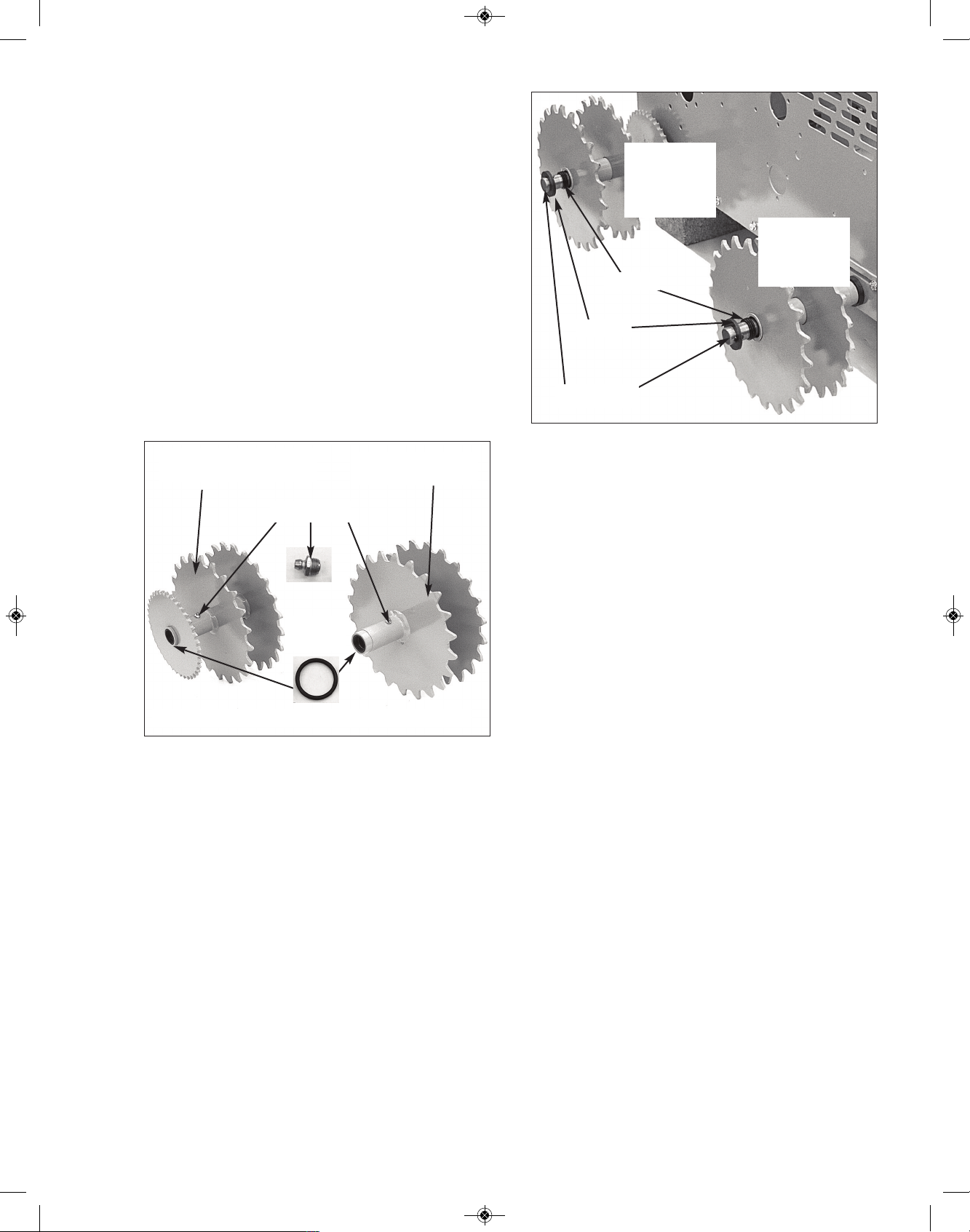
RUBBER TRACK SPROCKET ASSEMBLY
NOTE: In the photos that follow, the #4349
Rubber Track front idlers and #4350 Rubber
T
rack rear drive sprockets will look different
from what is shown, but the assembly process
will be the same. Please gather your parts you
set aside from your earlier track removal. Ex. Orings, Nuts, Bolt, Washers. They will be needed
for the re-assembly process.
1. Insert a #2061 grease zerk into the
threaded hole provided in the Tube of each of
the two (2) #4350 Rear Sprockets Assemblies
and the two (2) #4349 Front Idler Assemblies.
Tighten all four (4) Grease Zerks... See Photo
below.
2. Insert a set of three (3) #706 O-Rings into
the “inside end” of each Tube of #4349 and
#4350 Sprocket assemblies...as shown in the
Photo below. Do not do to the “outside end” at
this time.
3. Take the two (2) #4349 Front Idler assemblies and slip them onto opposite ends of the
#2065 Front Axle... push “assemblies” tightly
against #704 Washers... see photo at the top
ofthe next column.
NOTE: Rotating each Sprocket & Idler assembly, as you push it on it’s Axle, is very
helpful in moving it “inward”.
Use the photo above as a reference for
steps 4-7 below.
4. Take the two (2) #4350 Rear Sprocket as-
semblies and slip them onto opposite ends of
the #2065 Rear Axle...push “assemblies”
tightly against #704 Washers.
5. Slip the remaining sets of three (3) #706 ORings over right ends of #2065 Front & Rear
Axles...push them into their respective Tubes
of Front & Rear Sprocket assemblies.
6. Check that O-Rings are properly seated in
their respective Tubes and not getting pinched
or cut. At this point approximately 2” of Axle is
exposed on each end of each Axle.
7. Slip five (5) #704 Washers over both ends
of #2065 Front & Rear Axles and push them
tightly against their respective Tubes... check
that O-Rings are properly seated inside their
respective tubes.
8. On left and right side, slip a #1691 Track
Expander followed by five (5) #704 Washers
over both ends of #2065 Front & Rear Axles.
See photo at the top left of the next page.
52
704 (5)
2065 Axle
706 (3)
4349
Front Idler
Sprocket
4350
Rear Drive
Sprocket
4349 Front Idler
assembly
4350 Rear Sprocket
assembly
706
O-Ring
Set of (3) 706 O-Rings on “inside end”
2061 Zerk
RS1000 Operator Manual 1.01.19.qxp_Layout 1 4/24/19 12:43 PM Page 52

9. Secure Axles by sliping a #727 Snap Ring
over each Axle end and engage it into the
groove provided in each Axle.
TIP: You may need to use a new #727 Snap
Ring, as once removed, they are difficult to reuse. Photo below shows proper method of applying #727 Snap Ring. Ring is pulled apart
“accordion style” to allow you to work the Ring
around the axle. Keep working the Ring toward the “groove” until it falls in... make sure
both ends of Ring are in the groove, or the
Ring may potentially slide off during operation of tractor.
10. On right rear of Magnatrac, take your 1/2”
Bolt and insert it in the following order: 1/2”
Flat Washer, oval slot in top rear of #1691 Expander [right side], hole in #2056 Axle, oval
slot in bottom rear of Expander, 1/2” Flat
Washer and secure with 1/2” Nut... tighten,
but don’t crush Expander.
11. Repeat this STEP now using Expander on
left side of Magnatrac.
12. Insert #1810 Track Tension Bolt into
square hole in end of #1691 Expander assembly and pass through 1/2” hole in end of
#2065 Axle.
13. Over threaded end of #1810 Bolt slip on in
order: Five (5) 1/2” Washers, #1689 Washer,
#1806 Spring [with #1685 Tube inside], #1689
Washer and finally a few turns of Lock Nut...
you may have to move the Axle ahead slightly,
to get Nut on.
NOTE: Photo above shows only the right side
of the Front Axle...this assembly is intended
for both sides of the #2065 Front Axle.
For the next steps in the rubber track assembly process, please refer to:
REAR DRIVE CHAIN
AND CHAIN GUARD ASSEMBLY
Located on the next page.
53
1691 Expander
7
0
4
(
5
)
2065
Front & Rear Axles
727
Snap Ring
704 Washers (5)
Groove in Axle
1691 Expander
2065 Axle
1/2” Flat-
Washer
2
0
6
5
A
x
l
e
1/2” Nut
1/2” Bolt
1691 Expander
1810
(5) 1/2”
Washers
(5) 1/2”
Washers
1689
1689
1685
[“inside” 1806]
1806
1806
1689
Jam
Nut
Lock
Nut
2065
RS1000 Operator Manual 1.01.19.qxp_Layout 1 4/24/19 12:43 PM Page 53

REAR DRIVE CHAIN
AND CHAIN GUARD ASSEMBLY
The following bolded text should have been
completed in your steel track disassembly
process, if not, please do so at this time. Make
sure both ends of Rear Axle are forward so
that the #GG Nut hits its respective #1690
Washer on left and right side at rear of
Body... see Photo below.
1. Loop a #1805A Chain around each set of
Rear Drive Sprockets and #2048 Sprocket
Shaft on left & right sides of Body.
2. Join ends of each #1805A Chain with the
pins of each #1805B Connecting Link. Secure
each Link with Plate and lock with Clip.
NOTE: When installed, the pins of each Link
should point to the center of your Magnatrac...
see Photo at the bottom of previous column.
3. To tighten the Drive Chains start rotating
clockwise the #GG Nut located on left & right
lower rear of Body. To draw Rear Axle back
evenly, turn one Nut 1/4 turn, then go to the
other side and tighten the other #GG Nut 1/4
turn.
4. Tighten both Chains until reasonably tight...
not “bow-string” tight, but have about 1/4” of
“sag” in the slack strand when the balance of
the Chain is taught... See Photo below.
NOTE: When tightening Chains, rotate left &
right Rear Sprocket assemblies one full rotation after each 1/4 turn of tensioning. If you
detect a “high spot”, use that point to determine your 1/4” of Chain sag.
54
Loosen (4) Bolts
Left & Right sides
1690
Washer
GG Nut
hits #1690
Left &
Right sides
1657 Plate
Rear
Drive
Right Rear View
Push
2048
Sprocket
Shaft
Clip
Clip
Plate
Plate
Link faces
inward
Link
faces
inward
1805A
1805A
Rear
D
r
ive
Rear
Drive
2048
1805B
Co
n
necting
Link
1690
Washer
GG
Nut
Push
1/4” sag
1637
Spacer
U Bolt (3)
Left rear
Right rear
1636
Chain
Guard
RS1000 Operator Manual 1.01.19.qxp_Layout 1 4/24/19 12:43 PM Page 54

5. Closely following the Photo at the bottom
right of the previous page, insert three (3) #U
Bolts into outside face of each #1636 Chain
Guard. Slip a #1637 Spacer over each Bolt.
6. Install a Chain Guard assembly into 3/8”
holes in left and right rear Body Walls. Secure
inside Body Wall with #JJ Nuts... fully tighten
Nuts... see Photo at bottom right of previous
page.
7. Check your assembly: make sure the four
(4) Bolts securing the #1657 Plate [on “rear”
left and right side of Body] are firmly tightened.
RUBBER TRACK
CENTER IDLER SYSTEM ASSEMBLY
Prior to installing your center idler system,
onto each side of your tractor. You’ll need to
pre-assemble your #4352 L&R Idler Frame
and Idlers. Although, this creates more
weight to lift later in the assembly, this does
make the process easier.
1. Identify the #4352R and #4352L Idler
Frames by placing them upside down as
shown in the picture above. The bolt hole and
the steel angle bend should be on the LEFT
side for the #4352R Idler Frame and on the
RIGHT side for the #4352L Idler Frame.
2. Install (3) #706 O-rings into each side of the
#4351 Idler. The O-rings should rest against
the inside brass bushing. (See picture at the
bottom of opposite column). Note: Lubricat-
ing these O-rings with a light coating of
motor oil or another lubrication will help in
the assembly process. Do the same to the
other #4351 idlers. (You should be using 6 Orings per each idler. 3 for each side.)
3. Take a #4354 Center Axle and slide it
through the LEFT collar as shown above.
Next, add (2) #242 Shim Washers, then slide
your axle through the #4351 Idler, then add 2
more #242 Shim washers on the other side of
the Idler. Double check that your #706 O-rings
are still in place.
4. Slide the remaining end of the #4354 Center Axle through the RIGHT collar. Push
through fully. Do the same process to the
other 3 sets of #4354 Center Axles and #4351
Idlers.
55
4352R
43514354
(2)242
(3)706
4352R
Idler Frame
Assembly
4351
4352R
4351
4354
LEFT RIGHT
LEFT RIGHT
5/16” Spin
Lock Bolt
& Nut
5/16” Spin
Lock Bolt
& Nut
2061
4352R
Idler Frame
Assembly
BOLT
HOLE
ON LEFT
STEEL
ANGLE BEND
ON LEFT
4352R
Idler Frame Assembly
(Upside down view)
RS1000 Operator Manual 1.01.19.qxp_Layout 1 4/24/19 12:43 PM Page 55

5. Secure #4354 Center Axles with (1) 5/16”18 x 1 1/4” Spin Lock Bolt and (1) 5/16”-18
Spin Lock Nut...tighten. Insert a #2061
Grease Fitting into end of each #4354 Center
Axle...tighten. Do the same process to the
other 3 sets of #4354 Center Axles & #4351
Idlers. See picture at the bottom right of pre-
vious page.
Once assembly is complete, flip over your
#4352 L & R Idler Frame Assemblies. They
should look like the below picture. Note: The
#4352R Idler Frame Assembly is shown
below.
6. Remove the (3) bolts from each side
of the
body, for later re-assembly. See below.
For the next steps, Bolts 1, 2 and 5 are the
5/16” Bolts and nuts that you removed from
your body wall above. Bolts 3 and 4 are new
3/8” Bolts and Nuts. Having a helper available in this process to hold the assembly up
and spin on the nuts will make the process
much easier.
7. Loosely, attach Bolt - 1 through the #4352R
Idler Frame Assembly, then through the body
wall. Attach a 5/16” Nut to the inside of the
body wall. See picture below.
8. Loosely, attach Bolt - 2 through the #4352R
Idler Frame Assembly, then through the bodywall. Attach a 5/16” Nut to the inside of the
body wall. See picture below.
9. Loosely, attach Bolt - 3 & Bolt 4 through
the LOWER HOLES on the Track Expander,
then through the #4352R Idler Frame Assembly. Attach a 3/8” Nut to the inside of the
#4352R Idler Frame Assembly. See below.
10. Loosely, attach Bolt - 5 through the
#4352R Idler Frame Assembly, then through
the bodywall. Attach a 5/16” Nut to the inside
of the body wall. See below.
All bolts should be loose at this time. Repeat
Steps 6-10 to the other side of the tractor,
using the #4352L Idler Frame Assembly.
11. Drop in from above, (2) #4353 Shims between the #4352R Idler Frame Assembly
and the right body wall. Making sure the
openings are towards the bottom of the shims
when dropping them in. Shims are slotted, to
allow for bolt clearance. See picture on next
page.
12. Drop in from above, (2) #4353 Shims between the Track Expander and the #4352R
Idler Frame Assembly. Making sure the
openings are towards the bottom of the shims
56
4352R
Idler Frame
Assembly
Bolt
2061 2061
4351
4351
4354
Bolt - 1
Bolt - 2
Bolt - 3
Bolt - 4
Bolt - 5
5/16”
3/8”
4352R
Idler Frame Assembly
Track
Expander
RS1000 Operator Manual 1.01.19.qxp_Layout 1 4/24/19 12:43 PM Page 56

when dropping them in. See picture below.
13. Drop in from above, additional #4353
Shims on both sides, to allow approx.
equal spacing between track sprocket path
an idler wheel path. Tap shims gently with
hammer to allow them to “be seated”. Don’t
force excessive amount of shims.
14. Once happy with the spacing, make sure
to tighten all 5/16” and 3/8” Bolts and Nuts.
Repeat Steps 11-14 for the opposite side of
the tractor.
You are now ready to install your rubber
tracks, please refer to:
RUBBER TRACK
REPLACEMENT & TENSIONING
Located on pages 44-46 of this manual.
57
Shim
Idler Frame
Assembly
Track Expander
(2) Shims
(2) Shims
Track Expander
Idler Wheel Path
Track Sprocket Path
RS1000 Operator Manual 1.01.19.qxp_Layout 1 4/24/19 12:43 PM Page 57

8- TROUBLESHOOTING
Below are tips and guidelines for trou-
b
leshooting some problems or concerns, which
may occur during the life of your equipment.
Should these guidelines not solve a problem
please contact the factory for further instruction.
Engine won’t crank.
• There are 2 electrical safety switches on
every crawler (seat safety switch & brake
safety switch). If the safety switches are
not in contact; the switches will prevent the
engine from cranking. Make sure you are
sitting on the seat and that the parking brake
is engaged.
• With a continuity tester verify that the
Brake safety switch is operating properly.
• Check to see if the solenoid is working.
When you turn the key from run to off
position you should hear a clicking sound.
Have another person listen while an
operator tries to start the unit.
• Verify that the wiring is in good condition.
• Check fuse in Honda Igntion Box & Circuit
Breaker on front of Honda Ignition.
Engine cranks but won’t start or starts and
stops running right away.
• Verify there is adequate fuel & that the fuel
filter is in good condition. Take off the fuel filter and fuel line by the tank. Check to make
sure the fuel line and/or tank is not clogged
with any debris. Check hoses leading to the
fuel pump and to the carburetor. Also, check
that the fuel shutoff is in the open position.
• Verify seat safety switch is being engaged
and operating properly. The connection
may be loose.
• Replace with new fuel.
• Carburetor may be clogged.
Engine dies when not in the seat.
• This is a normal operating characteristic to
safeguard against accidental engagement of
the tractor and/or attachments while not
p
roperly located in the operator’s seat.
•
If the engine dies continuously, check the
wire connections and verify wires are not
frayed or damaged.
Do Not Bypass this safety feature by completing the wire circuit.
Hydraulic Attachments (If equipped) behave
erratically.
• Verify hydraulic fluid level is within the required operating range. Low fluid levels can
result in air intake to the hydraulic system,
which can result erratic operating characteristics.
• Verify the suction lines are properly secured.
Loose suction lines can result in air intake
and erratic operation.
• Check hydraulic pump belt. See PP35
Power Pack Instructions.
Track tensioning adjustment has reached its
limit, but tracks are still loose.
• It is possible to remove links from the “steel
track” chain to shorten the track loop. See
the Service section of this manual. Contact
factory for details.
• Tension springs or tracks need to be re
placed.
One cylinder function of an attachment is not
responding.
• A non-functioning cylinder can result from either a problem with the cylinder or the valve
section operating the cylinder. To test, take
the two hoses of the non-functioning cylinder and switch their connection at the operating valve with those of the adjacent valve
section.
• If the non-functioning cylinder continues
to not operate the cylinder is faulty.
• Should the cylinder now work, but the
cylinder of the control that was switched
stops working problem lies in the valve
section.
58
RS1000 Operator Manual 1.01.19.qxp_Layout 1 4/24/19 12:43 PM Page 58

MAGNATRAC has little power.
• Verify engine throttle is adequate; check the
t
hrottle connections.
•
Verify there are not external loads draining
engine power.
• Check the condition of the rear clutch belts,
they may need to be tensioned or replaced if
broken. (See the Service section of this
manual).
Tracks are making a popping sound.
• It is not uncommon in the initial operating
hours for the steel track system to make
popping noises as the initial wear in occurs.
• Debris (rocks, branches, etc...) drawn into
the track system will most likely be crushed,
broken, or shattered resulting in popping
noises. Check for stuck items in the track
like rocks or other debris.
• Verify the track tension on the front idler
sprockets is evenly adjusted on the left and
right of the track. Unequal tensioning can
result in the front idler sprocket running at
an angle not parallel to the track line. (See
the Service section of this manual). This results in tracks riding up the teeth of the
sprocket and snapping back down to produce a popping noise.
• Check track sprockets for heavily worn teeth
that would allow the sprocket to jump inside
the tracks.
• Verify that the tracks are tensioned. Exces-
sively loose tracks can result in the drive
sprocket jumping inside the tracks.
MAGNATRAC does not drive perfectly
straight.
• Due to normal inefficiencies in adjust han-
dles, each track must be individually controlled to achieve a straight travel path.
Operating both drive handles equal distance
will naturally result in a “slightly” curved
travel path. If this condition is extreme, contact the factory for possible problems
Tracks came off.
• Do NOT proceed operating the MAGNA
T
RAC. Lower all attachments and apply the
parking brake. Inspect the area for causes.
See the Service section of this manual for
possible problems and fixes. Call the factory
with questions.
MAGNATRAC is stuck.
• Use the hydraulic down pressure (if
equipped) of the attachments to loosen the
tracks. Call the factory with any questions.
• To tow the MAGNATRAC: Lower all
attachments so that they are just above the
ground. WE NEVER ADVISE TO PUSH! See
additional instructions below.
1. Make sure the parking brake is
disengaged.
2. Remove seat and rear cover
assembly.
3. Remove any cross braces that
prohibit access to the belt area.
4. Loop rear clutch belts off of pulleys.
This can be done in a variety of ways.
(See belt removal section in this man
ual).
No power to your attachments.
• Check the condition of the attachment
pump belt, (if equipped) located by the eng
ine. Tension or replace. See PP35 Power
Pack Instructions for detailed infomration.
Hydraulic Oil is overflowing from the hydraulic oil breather.
• Check the level of the oil in hydraulic tank (if
equipped), level when full should be approx.
5” from the top of the tank.
• Check the rating of your 3rd party
attachment that may be connected to the at
tachment valve. Call the factory with ques
tions.
59
RS1000 Operator Manual 1.01.19.qxp_Layout 1 4/24/19 12:43 PM Page 59

9- SAFETY & WORK PROCEDURES
for MAGNATRACS
The following material is designed to familiarize you with the basic characteristics
of a MAGNATRAC (tracked Vehicle). Its purpose is to teach you how a MAGNATRAC
responds in comparison to the more familiar wheeled tractors. In addition, it outlines
safe and efficient work procedures for a compact crawler tractor equipped with optional
attachments (loaders, backhoes, blades, etc.)
Each MAGNATRAC operator encounters dramatically different working conditions than another. For this reason the following drawings and descriptions are general
in nature. They illustrate general points rather than details which may apply to only one
operator’s working conditions. You are encouraged to contact the factory at anytime for
help or advice for any job you have in mind.
60
RS1000 Operator Manual 1.01.19.qxp_Layout 1 4/24/19 12:43 PM Page 60

A
tracked Vehicle, by its very nature, requires the use
of operating techniques and procedures that are unfamiliar to most people used to driving wheeled vehicles.
T
his means that a person intending to operate a
Tracked Vehicle must allow himself ample opportunity to
familiarize himself with the controls and characteristics of
the machine.
It is the purpose of this booklet to inform and instruct
prospective Track Vehicle operators in an effort to help
them use it safely.
SAFETY WARNING: NO PERSON SHOULD ATTEMPT TO OPERATE A TRACKED VEHICLE
BEFORE READING THIS BOOKLET THOROUGHLY. IF ANY PORTION OF THIS BOOKLET IS NOT CLEARLY UNDERSTOOD, WRITE
TO US AT THE ADDRESS ON THE FRONT
COVER.
TRACKED VEHICLE CHARACTERISTICS
Tracked vehicles possess certain inherent features
not found on standard four-wheel vehicles. For instance,
a standard vehicle will hit bottom when the wheels on either end are driven over a drop-off. In most cases this will
stop vehicle motion and give immediate warning.
A tracked Vehicle, however will continue on without any
warning until its center of gravity passes across an imaginary line drawn straight up from the furthermost point of
support with ground. It will drop SUDDENLY. (See illustration upper right). THIS WILL HAPPEN EVEN AT THE
VERY SLOWEST SPEEDS.
S
AFETY WARNING: ANYTIME A PORTION OF
THE TRACK IS NOT IN CONTACT WITH THE
G
ROUND, STABILITY IS REDUCED. NEVER ATTEMPT TO ‘JUMP’ A TRACKED VEHICLE
OVER DROP-OFFS, HILL CRESTS, OR OTHER
OBSTACLES. THIS CAN BE EXTREMELY HAZA
RDOUS.
A Tracked Vehicle can climb or descend steep slopes, so
steep in fact that the vehicle can tip over forward or backward, before it loses traction.
Tipover occurs when the Vehicle’s center of gravity
passes across an imaginary line drawn straight up from
the furthermost point of support with ground.
When the vehicle’s center of gravity passes this point,
the vehicle will tip over SUDDENLY.
61
RS1000 Operator Manual 1.01.19.qxp_Layout 1 4/24/19 12:43 PM Page 61

T
RACKED VEHICLE OPERATION
A Tracked Vehicle, by its very nature, is a vehicle requiring a great degree of care and judgment during operat
ion. It should be kept in mind that while your Tracked
Vehicle is designed to operate in rough terrain, this same
fact allows for the possibility of a hazardous condition developing at any time. Safe operation of your Tracked Vehicle must be based on the understanding of the vehicle’s
limitations, thorough knowledge of the controls and their
functions, and the operator’s good judgment and experience.
SAFETY WARNING: WHERE THE OPERATOR
IS NOT CERTAIN OF THE VEHICLE’S ABILITY
TO TRAVERSE AN OBSTACLE OR TERRAIN
SITUATION, OR, IS NOT CERTAIN OF HIS OWN
ABILITY TO SAFELY OPERATE THE VEHICLE,
AN ALTERNATE ROUTE MUST BE TAKEN.
OPERATION ON SLOPES
Tracked Vehicle operation on slopes presents an obvious opportunity for the vehicle to tip over. This type of operation demands constant attention to changes in terrain
and the ability to anticipate and avoid possible hazards.
This ability can only be developed through careful
study of the points noted in this section and a slow,
planned effort on the operator’s part to become proficient.
The most effective guard against hazards while operating on slopes, especially during downhill operation is to
keep vehicle speed very slow.
SAFETY WARNING: WHEN OPERATING ON
SLOPES VEHICLE SPEED SHOULD BE KEPT
VERY SLOW AND THE OPERATOR SHOULD BE
EXTREMELY ALERT FOR CHANGES IN TERRAIN.
Vehicle stability on a hill, for example, is determined
not only by the general slope of the hill but also by terrain
conditions (rocks, ditches,, logs, drop-offs, etc.) and by the
nature of the hill surface (gravel, sand, grass, snow, rock,
etc.), the payload which the vehicle is carrying, the manner in which the payload is distributed within the vehicle,
attachments and accessories which have been added to
the vehicle, and so forth.
Similarly, driving technique and its effect on vehicle
stability enters into any determination of what constitutes
a safe slope. Excessive speed, sudden braking, choice of
path - all can be critical.
UPHILL OPERATION
The following illustrations depict some situations in
which a Tracked Vehicle can be expected to tip over. Variations in speed, loading, terrain and vehicle condition
must all be analyzed to determine whether or not a spe-
c
ific obstacle can be traversed. If in doubt, do not at-
tempt.
SAFETY WARNING: ON STEEPER SLOPES
SMALLER OBSTACLES WILL CAUSE A TRACKED
VEHICLE TO TIP OVER.
It is common to see a situation where a natural ero-
s
ion has caused the very top of a bank or hill to rise
sharply. Always check for this condition before attempting
to climb any such type of terrain. A Tracked Vehicle could
climb up to a point at which it falls over backward.
It is also very important to check for this terrain condi-
tion before going down over the edge of a bank or dropoff.
The same situation can occur where an embedded
object is pulled from the ground. The vehicle track may
‘grab’ a rock or log. As the object emerges from the
ground, rolling under the track, the vehicle could climb to
the point at which it falls over backward.
62
RS1000 Operator Manual 1.01.19.qxp_Layout 1 4/24/19 12:43 PM Page 62

63
DOWNHILL OPERATION
SUDDEN STOPS
If a Tracked Vehicle is driven down a slope and the
tracks are stopped suddenly, the vehicle’s exceptional
traction may cause it to tip over forward.
SAFETY WARNING: IF VEHICLE MOTION IS
ABRUPTLY DECREASED OR STOPPED, A
TRACKED VEHICLE CAN TIP OVER FORWARD. THIS POSSIBILITY BECOMES
GREATER AS THE VEHICLE SPEED AND/OR
DOWN SLOPE INCREASES.
CROSSING OVER AN OBJECT
This illustration is drawn to depict an obstacle situation in which a Tracked Vehicle can be expected to tip
over. Variations likely to occur in natural terrain, the approach to the obstacle, operator skill and loading of a
Tracked Vehicle may reduce the size of obstacle or steepness of the slop required, which could cause tipover.
SAFETY WARNING: IF THE VEHICLE’S CENTER OF GRAVITY PASSES THE POINT OF
SUPPORT, A TRACKED VEHICLE WILL BEGIN
TO TIP. UNLESS THE TERRAIN ON THE
DOWNSIDE OF THE OBJECT PROVIDES A
NEW POINT OF SUPPORT, FAR ENOUGH
AHEAD OF THE VEHICLE CENTER OF GRAVITY TO NEGATE THE EFFECT OF INERTIA, A
TRACKED VEHICLE WILL TIP OVER FORWARD.
SAFETY WARNING: ON STEEPER SLOPES,
SMALLER OBSTACLES WILL CAUSE A
TRACKED VEHICLE TO TIP OVER.
SAFETY WANING: OBSTACLES, SOME OF
W
HICH MIGHT BE DRIVEN OVER SAFELY
WHILE ON LEVEL TERRAIN, CAN CAUSE A
HAZARD WHILE OPERATING ON SLOPES.
D
ROPOFFS
This illustration is drawn to depict a dropoff situation in
which a Tracked Vehicle can be expected to flip. Variat
ions occurring in natural terrain, the approach to the obstacle, operator skill, and loading of a Tracked Vehicle
may reduce the size of the dropoff or the steepness of the
slope, which could cause tipover.
SAFETY WARNING: A TRACKED VEHICLE
MUST BE OPERATED WITH GREAT CARE AT
ALL TIMES AND ON ANY SLOPE. SLOPES
STEEPER THAN 20° SHOULD BE REGARDED
AS ULTRA-HAZARDOUS AND APPROACHED
WITH EXTREME CAUTION. EVEN ON SLOPES
OF LESS THAN 20°, A TRACKED VEHICLE
CAN BE TIPPED OVER BY A SUDDEN STOP,
EXCESSIVE SPEED, UNEVEN TERRAIN, OR
OTHER SPECIAL CONDITIONS OR COMBINATIONS OF SUCH CONDITIONS.
An important variable in determining if a give obstacle
will cause a Tracked Vehicle to tip over is the vertical distance between the last point of contact and the new point
of support. Note that the new point of support can be on
level ground, a downhill slope, or a steeper downhill slope.
The apparent size of the obstacle or dropoff is not the
same as the drop it causes. Among the many other vari-
RS1000 Operator Manual 1.01.19.qxp_Layout 1 4/24/19 12:43 PM Page 63

variables are the steepness of the slopes, size of the obstacle causing the drop, the shape of the last point of support, the load on the Tracked Vehicle, initial speed,
t
ightness of the track, traction, symmetry of the obstacle to
the Tracked Vehicle and operator skill and judgment.
SIDEHILL OPERATION
The illustrations show how driving over an obstacle
withe the uphill track or into a hole with the downhill track
will cause the vehicle to tip over sideways.
A slippery surface, like snow, ice, frozen sand, and
loose gravel can also be dangerous. It is possible to slide
into a tree or rock or to slide off the edge of a cliff.
SAFETY WARNING: REGARD ALL OPERATIONS
ON SLOPING TERRAIN AS HAZARDOUS.
PARKING THE VEHICLE
When a Tracked Vehicle is parked on a sufficient
slope, failure to engage the parking brake, or failure of the
parking brake to function properly-can result in the vehicle
rolling down the slope, out of control.
OPERATING SAFETY PRECAUTIONS
1. Keep hands and feet inside vehicle.
2. Never attempt to operate the vehicle from anywhere
o
ther than the driver’s seat.
3. Avoid unnecessary quick stops.
4. Avoid quick turns.
5
. Shut off engine and engage parking brake when leav-
ing vehicle.
6. Park sideways on slopes.
64
RS1000 Operator Manual 1.01.19.qxp_Layout 1 4/24/19 12:43 PM Page 64

L
OADER OPERATION
Suggested operating techniques for loader operation
are outlined in this section. Practice the lever movements
as you operate the loader through the various jobs described.
Filling the Bucket
Set the bucket to the level position. Approach, then
enter the pile.
Ease the control levers to lift and roll back the bucket.
Lift and roll back of the bucket will increase efficiency
because a level bucket throughout the lifting cycle re-
sists bucket lift and increases breakaway effort.
NOTE: Do not be concerned if the bucket is not com-
pletely filled during each pass. Maximum productivity is determined by the amount of
material loaded in a given period of time.
Time is lost if two or more attempts are made
to fill the bucket on each pass.
LIFTING THE LOAD
To lift and carry the load, without spillage, fully roll the
bucket back after filling and before moving the unit.
NOTE: Do not attempt to lift bucket loads in excess of
loader capacity.
PEELING AND SCRAPING
USe down pressure and a slight bucket angle to start
long cuts. Make a short angle cut and break out cleanly.
W
ith the bucket level, start a cut at the notch approximately 2 inches (50.8 mm) deep. Hold the depth by feathering the bucket to adjust the cutting lip up or down.
When the front of the tracks enter the notch, adjust the lift
a
rms to maintain the proper depth.
Make additional cuts until the desired depth is
reached.
After reaching the desired depth, actuate the loader
control lever to compensate for bucket lip action only; do
not move the lever for lift cylinder action. Doing this allows you to concentrate on maintaining a precise cut.
If the lever is moved for lift cylinder action without controlling the bucket angle, the bucket may gouge and leave
a series of ruts in the surface.
65
RS1000 Operator Manual 1.01.19.qxp_Layout 1 4/24/19 12:43 PM Page 65

OPERATING WITH FLOAT CONTROL (if equipped)
During hard surface operation, place the control lever
in “float” (held by the detent), and keep the bucket level.
This will permit the bucket to “Float” on the contour of the
w
orking surface. If hydraulic down pressure is exerted,
the bucket will wear faster than normal.
The ‘float” position will prevent the mixing of surface
m
aterial with stockpile material. It will also reduce the
chance of surface gouging when removing snow or other
material.
CARRYING THE LOAD
Position the bucket in the full roll back position and the
lift arms as low as possible for maximum stability and visibility whether the bucket is loaded or empty.
CAUTION
: When operating on a hill or slope, keep
the bucket as low as possible. This keeps the
bucket center of gravity (C/G) as low as possible,
giving maximum stability.
When transporting the load, keep the bucket as low as
possible to resist tipping, in case a track drops in a rut.
DUMPING THE BUCKET
Lift the bucket high enough to clear the side of the vehicle. Move unit in as close to the side of the vehicle as
possible, then dump the bucket.
After the bucket is dumped, back away from the vehicle while lowering and leveling the bucket.
BACKFILLING
Efficient backfilling occurs by pushing maximum
amounts of soil without losing speed or “stalling.” If a
“stall” occurs, downshift or reduce the depth. If the unit is
not working at capacity in the gear selected, increase the
depth of the cut.
Approach the pile with a level bucket. When adjusting
the depth of cut to a load that can be handled without
going into a “stall,” actuate the control lever for lift and
bucket action simultaneously, or separately as required, to
maintain a level bucket.
Leave the soil in the bucket, as dumping on each pass
is time consuming. Lift and level the bucket for the next
pass while backing from the excavation.
Operate at right angles to the ditch.
66
RS1000 Operator Manual 1.01.19.qxp_Layout 1 4/24/19 12:43 PM Page 66

L
eave soil that drifts over the side of the bucket for
final cleanup.
One lengthwise cleanup pass will usually leave the
b
ackfill at an acceptable grade.
W
hen backfilling from a large pile, shovel off the top of
the pile, pushing toward the excavation. Drag some soil
r
earward to form a work ramp of convenient grade.
When backfilling on a slope, have the soil piled on the
high side for easier backfilling.
L
OADING FROM A STOCKPILE
I
nitially approach the stockpile with the bucket approximately 2 feet (609.6 mm) off of the ground. Lower the
b
ucket to ground level when the stockpile height has been
reduced so the bucket will break out easily.
Keep an area clean so the truck or trailer can back in
close to the work area. This will minimize travel distance
from the pile to the truck. Keep the truck in close and
work around the pile.
LOADING FROM A BANK
Select the highest forward gear that provides the most
efficient loading operations without going into a “stall.”
For faster loading, maintain a 45° turn angle, and work
as close to the truck as possible.
67
RS1000 Operator Manual 1.01.19.qxp_Layout 1 4/24/19 12:43 PM Page 67

A
lways keep the truck close to the operation and keep
cutting depth half the length of the truck bed.
Backgrade with the bucket occasionally, and approach
t
he bank with the bucket flat. Slight down pressure with
the bucket level helps keep the working area smooth.
Use the heel or low rear edge of the bucket for back-grading ruts, etc.
CAUTION: Exercise care when undercutting high
banks. Soil slides can be dangerous. Load from the
banks as low as possible for maximum efficiency.
Remember that loader lift and break-away capacities
diminish rapidly as loading height is increased.
BREAKING AND SPREADING LARGE PILES.
Side-cutting is a good technique for cutting down a
large stockpile.
I
f the pile sides are too high and are likely to cave in,
use the loader to break them down.
Then, build a ramp by shovel-loading material from
the top until a work area is cut through the pile.
If stuck in a ditch...
...dump the bucket and apply down pressure to lift the
front of the tracks from the ditch. Actuate the bucket as
engine power is applied to move the unit backward.
68
RS1000 Operator Manual 1.01.19.qxp_Layout 1 4/24/19 12:43 PM Page 68

BULLDOZING
DOZER EXCAVATION
When dozing out a pit with a blade or bucket, make
cross cuts working from South to North in overlapping
swaths. When the bucket or blade fills, lift and push cont
ents over the undug ground which will later be dozed to
the opposite side and then out.
You have to work down from ramps on either side of
opening until the desired depth and area are achieved.
You should leave one ramp intact so that trucks can deliver foundation materials where they will be used. If soil
is excessively hard, loosen it with a ripper or plow. The remaining ramp can be cut out with either a backhoe or by
hand.
When regular loading tools are not available it is possible
to utilize bulldozers for filling tracks and trailer. Inclined
ramps, built of earth, steel or wood, are a means to assist
loading economically when level terrain predominates.
D
OZER DITCHING
A
dozer and blade can dig wide, shallow ditches effectively as shown in the following illustrations. When the
l
imits for side excavation are reached (A)...
...the unit can work in the trench pushing the material
forward into mounds (B), that can then be pushed to the
side (C).
69
RS1000 Operator Manual 1.01.19.qxp_Layout 1 4/24/19 12:43 PM Page 69

SIDE HILL CUTS
Always start or pioneer all side hill cuts from the top of
h
ills and then work your way down with the cut. It may be
necessary to reach the starting point by climbing up a
more gradual slope on the opposite side of the hill. Working downhill gives you the advantage of gravity.
1. Working from above
On average terrain start cuts working straight down
t
he hill making short passes to bench out an area (A)
large enough so that the tractor can eventually turn and
work parallel to the road (B).
Keep pioneering cuts sloping into the uphill side (C)
for maximum earthmoving efficiency.
Make short swinging passes as you work downhill to
drift material over the side of the cut 9(D).
2. Working from Side (only)
A short, wide shelf may also be cut in a hillside, work-
i
ng from the side only as illustrated below.
T
he first cut (A) is made parallel to the hillside, followed by a second cut (B) in which the tractor’s inside
track rides in the trough formed by the previous cut. This
tilts the tractor to a more level position (depending on
depth of trough) and allows succeeding cuts C, & D to be
made parallel to the desired finish level.
Always keep the fill end high, as the tractor will mire
less if it can back up going down grade.
Do not push material further than absolutely necessary in order to stay on firm footing. When backing up, do
not raise blade. Raising the blade puts extra weight on
the front idlers causing greater track penetration. Let
blade float as you back away from the edge of soft fills.
70
RS1000 Operator Manual 1.01.19.qxp_Layout 1 4/24/19 12:43 PM Page 70

E
ARTH MOVING
W
hen stripping soil from a road or driveway, either
push it forward and angle it to the side (A) or push it forw
ard, then perpendicularly push it to the side (B).
Dirt can be piled by dropping successive loads together, then leveling this material and repeating the
process at a higher plane (A). In the alternative, loads
can be dumped in the opposite direction, creating the new
plateau while pushing loads forward (B).
Both methods will work. When working in heavy
growth or particularly hard soils, plow or rip the area prior
to dozing.
B
ACKFILLING
A
ngling blade bulldozers are excellent for backfilling
ditches as they can drift material into the trench while
m
aintaining forward motion.
With straight blade dozers, approach at an angle and
end up each pass by swinging into the structure or culvert
for smooth, fast results.
FINISH DOZING
Side slopes can be finished with a dozer by starting at
the top and traveling parallel to the right-of-way. Earth
from each pass will fall to the lower side of the blade and
form a windrow. This material is then picked up on succeeding passes filling up irregularities in terrain. Don’t
allow blade corner to dig as the slope will steepen beyond
job specifications.
71
RS1000 Operator Manual 1.01.19.qxp_Layout 1 4/24/19 12:43 PM Page 71

Another method commonly used: Start at the bottom
and travel diagonally up the slope. In this way a windrow
will be continually drifted to one side and will tend to fill
l
ow spots or irregularities.
When finishing in non-solid materials, such as earth,
drag the blade backwards for a smooth job. Rock, of
course, may damage the blade base, so such practice is
not to be recommended where abrasive material is comm
on.
CRAWLER TIPS
For Safety & Dozing Success
Don’t back up further than necessary and don’t push earth
for greater distances than required. These are common
faults of inexperienced operators. Always have a plan of
operation!
When dropping down a steep hill or over the side of a fill,
use blade for a brake.
When traveling, carry the blade low. This practice helps
protect drivetrain and other vital parts of the tractor.
If possible “slot doze” to keep load from spilling around the
sides of the blade.
TECHNIQUES FOR COMPLETING VARIOUS PROPERTY IMPROVEMENTS
W
hen enlarging ponds or streams, leave a ridge between the water and the excavation. When a desired
depth is reached, dig out the ridge.
When excavating ponds or streams, leave a ridge between the water and the excavation. When a desired
depth is reached, dig out the ridge.
When excavating wet soupy material construct a dry
soil dike and place watery mud behind this structure to
keep it from running back in the work area.
72
RS1000 Operator Manual 1.01.19.qxp_Layout 1 4/24/19 12:43 PM Page 72

BACKHOE OPERATION
TERMINOLOGY
STABILITY
Stability is the key to backhoe performance. The following information and illustrations pertaining to stability
should be carefully studied prior to operating the backhoe.
To increase stability for a digging operation, position
the loader bucket flat on the ground. Apply sufficient down
pressure on the bucket to transfer weight from the front of
the tractor to the loader bucket.
IMPORTANT: The loader bucket must be flat on the
ground. ROlling the bucket forward so the cylinders
are extended may cause bucket cylinder or rod damage.
During normal digging, as the bucket penetrates the
ground and is filled, there is a tendency for the rear of the
Tractor to raise off the ground and move toward the
bucket. Properly set, the stabilizers anchor the Tractor
and prevent it from moving toward the bucket. The ability
of the stabilizers to hold depends on the amount of weight
acting on them.
When lifting a full bucket, there is a tendency for the
f
ront of the tractor to rise. COunterweight in the form of a
ballast box is required to overcome this tendency. The
backhoe should not exert more lift force than the effective
counterweight can balance. Effective counterweight is the
weight of the tractor from the stabilizer pads to the loader.
Set the stabilizers to remove weight from the rear
track wheels. The tracks are to remain touching the
g
round as this provides for the widest stabilizer stance
and the lowest center of gravity. Raising the tracks off the
g
round will not only reduce stability and digging depth, but
will impair performance and impose unnecessary stress
on the unit.
Stability is particularly important when operating the
backhoe at the extreme swing positions, because the tendency is to lift one stabilizer and transfer the total weight
of the unit to the other stabilizer.
FILLING THE BUCKET
Operate two or more levers at the same time throughout the filling cycle for smooth action and maximum performance.
Control the bucket attitude throughout the digging
cycle to keep the teeth at the proper angle for best penetration. This will minimize dragging and scraping the
bucket through the ground.
When digging in hard-packed soil, bucket penetration
can be increased by applying down pressure with the boom
while crowding in and curling the bucket. If the crowd action
“stalls,” it may be necessary to apply lift occasionally during
the digging cycle to correct the bucket depth.
To obtain a cleaner trench and avoid the buildup of
BOOM
D
IPPER
BUCKET
STABILIZER
BOOM
SWING
LIFT
(
Up-Down)
BALLAST BOX
CROWD
(In-Out)
BUCKET
(
Curl In - Curl Out)
73
RS1000 Operator Manual 1.01.19.qxp_Layout 1 4/24/19 12:43 PM Page 73

during the digging cycle to correct the bucket depth.
To obtain a cleaner trench and avoid the buildup of
material directly in front of the backhoe, crowd out and
completely curl the bucket while starting to lift it from the
excavation. In this way, excess material will fall back into
the excavation.
MOVING THE TRACTOR TO THE SIDE
Lift stabilizers clear of the ground, curl the bucket approximately halfway and crowd in so the dipstick is nearly
vertical.
NOTE: The dipstick pivot, bucket pivot, and the point
where the bucket contacts the ground should be aligned
to reduce stress on the bucket and crowd cylinders.
(Bucket forward of the boom-to-dipstick pivot).
Apply sufficient down pressure with the boom to raise
the rear of the tracks off the ground. Slowly actuate the
swing control lever to move to the right or left as required.
Reset stabilizers and continue digging.
D
UMPING THE BUCKET
T
o dump the bucket at the end of the digging cycle, lift
the bucket clear of the trench while crowding it out and
s
winging it to the spoil pile.
A
s the pile is approached, dump the bucket. When
the bucket is empty, the dipstick and bucket are in position
t
o resume digging upon return to the trench.
IMPORTANT: Avoid constant jarring or hammering
type contact between the spoil pile and the loaded
bucket as this may cause premature wear to the backhoe pins and bushings.
TRENCHING
Trenching is the most basic backhoe digging operation. Other digging operations are merely variations of
this basic function (i.e. filling the bucket, dumping the
bucket, and moving the unit forward).
While trenching, it is generally important to maintain a
level trench bottom. This is accomplished by setting the
bucket at the proper angle of approach. As the bucket is
crowding in, continuously push on the bucket lever to
maintain the correct cutting angle. At the same time, pull
on the lift lever to relieve down pressure and keep the
bucket in the same plane.
TRENCHING BETWEEN A BUILDING AND OPEN EXCAVATIONS.
Start the trench at the building. Trench out halfway to
the excavation. Then, start trenching from excavation to
the first trench. Dig toward the first trench until there is
just enough room to move the unit out from between the
two trenches.
Position the unit so the backhoe swing post is over the
centerline of the trench connection. Dig with the backhoe
at extreme swing position, and in close to the stabilizers
74
RS1000 Operator Manual 1.01.19.qxp_Layout 1 4/24/19 12:43 PM Page 74

stabilizers as possible. Pile the spoil on the opposite side
of the trenches.
C
ontinue the trench by moving the Tractor forward.
Moving too far will require excessive down pressure for
digging, plus hand clean-up of the trench bottom. It is better to move a lesser amount than to move too far.
Position the unit forward so the two trenches can be
connected. Pile the spoil on the opposite side of the
trench.
SIDE SLOPE EXCAVATING OR TRENCHING
Dig with the backhoe uphill whenever possible.
Level the backhoe on slopes with the stabilizers to dig
plumb trenches, or...
...use the backhoe or loader to cut a level slot for the uphill
track and stabilizer. Pile ten spoil from the slot on the low
side.
When on the side of a steep slope, cut a level surface
along the uphill side of the trench with the loader. Pile the
spoil of the cut downhill. When digging, pile the spoil of
the trench uphill.
Dig field tile trenches progressively. As soon as one
trench is completed, have the workmen lay the tile. Start
the next trench, using the spoil to fill the previous trench.
75
RS1000 Operator Manual 1.01.19.qxp_Layout 1 4/24/19 12:43 PM Page 75
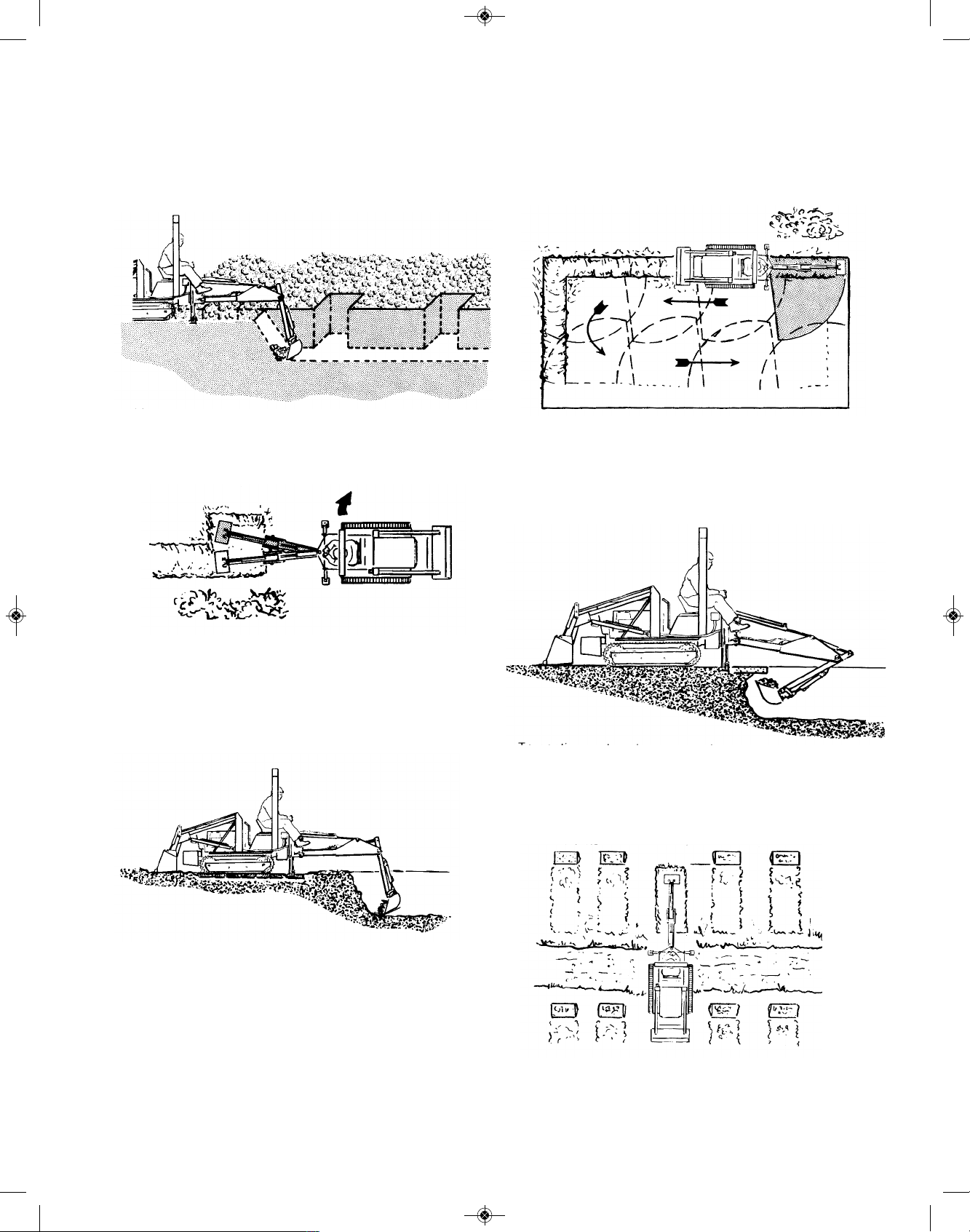
CONTINUOUS TRENCHING WITH SPACED BELLHOLES
B
egin by digging the trench to the desired grade.
Progress along the trench to the bellhole locations and dig
as much of the bellhole as possible without moving the
backhoe from the trench line setting.
Move to the side as previously described and complete the bellhole. Realign the backhoe with the trench,
and proceed trenching to the next bellhole.
When finishing straight walls or bellholes in sandy soil,
use a platform under the rear of tracks and the stabilizers.
The platform distributes the load over a larger area and
lessens the possibility of a cave-in. The platform also
tends to keep the unit from creeping rearward if hard digging is encountered.
DIGGING STRAIGHT WALL SHALLOW BASEMENTS
Begin at one corner, removing a much material as
p
ossible to grade level. Then, reset the unit forward and
continue digging to grade. Progress around the edge of
the basement, finishing each corner as you come to it.
DIGGING UNDER A SIDEWALK OR CURB
To continue a trench or excavation under a sidewalk
or curb, position the backhoe as shown.
GRAVE DIGGING
For the best grave digging position, back the tractor
straight in toward the grave site.
76
RS1000 Operator Manual 1.01.19.qxp_Layout 1 4/24/19 12:43 PM Page 76

W
hen grave markers prevent a straight-in position
back the tractor in at a 45° or 90° angle to the grave site.
Position the tractor close enough to the grave to dig a
full depth straight wall at the far end of the grave.
Start digging in the middle of the grave. At first, take
shallow bites around the edges to avoid damage to the
surrounding sod. After a on-foot (304.8 mm) depth is
reached, full buckets can be removed, wherever possible.
When the desired depth is reached, finish the end
walls. Finish the far wall by crowding out and forcing
down.
Lift up and crowd in to finish the close end wall.
P
IPELINE LEAK REPAIR
Locate the pipeline with a bellhole about six feet (182
cm) wide and tenn feet (304 cm) long. Then dig lengthwise along the pipeline to locate the leak.
When the leak is located, position the unit to dig at
grade level on both sides of the pipeline.
If a length of pipe must be replaced, strip the soil form
both ends of the bellhole. Dig the bellhole or trench large
enough to allow the workmen adequate space in the leak
area.
BACKFILLING
Backfill by lifting the bucket over the spoil pile and
then crowding in. Pull both the crowd and lift levers for
smooth, even backfilling.
IMPORTANT: Do not backfill by using the swing
circuit and dragging the bucket sideways.
Doing so can cause damage to the dipstick,
boom, swing cylinders, or main-frame.
77
RS1000 Operator Manual 1.01.19.qxp_Layout 1 4/24/19 12:43 PM Page 77

78
MISCELLANEOUS
SNOW PLOWING
Snow is bulkier than dirt and its slippery consistency
d
iminishes traction. When clearing snow, it is important to
push the load to the back of the piling area because it
c
annot be reached again.
W
hen snow is particularly heavy, paths can be cut
with a straight blade in a herring bone pattern. Passes
can be curving to the sides or straight and are stopped as
soon as the load gets too heavy to push.
When plowing a garage drive, make consecutive
passes to the side of the garage entrance, the obvious objective being to avoid piling snow against the door.
T
REE REMOVAL
L
ight trees and brush are removed by lowering the
blade a few inches into the ground just enough to strike
a
nd cut roots...usually done in first or second gear. An occasional backing up may be necessary to clear the blade
so it can always cut cleanly. Otherwise the blade will slide
over root and accomplish little.
Heavier trees and brush require more car and time to
uproot. First contact tree with blade high and centered for
maximum leverage. Make contact gently...push a few
times at half throttle while watching the top carefully. Look
for dead limbs - they’re widow makers! If tree seems in
good condition open the throttle and try again.
Lower blade into the ground and doze exposed roots
and tree completely clear of the ground.
To remove the larger trees follow a 3 step procedure:
First, determine the direction of fall...usually in the direction of lean...and then make a few passes on the opposite
side to a depth of say, 2 feet, or enough to cut some of the
larger roots.
Second, cut roots on both adjacent sides in a similar
manner.
Build an earth ramp up to the starting side of the tree
to get still more leverage and then push. As the tree starts
RS1000 Operator Manual 1.01.19.qxp_Layout 1 4/24/19 12:43 PM Page 78

79
to fall over, reverse tractor quickly, for the roots pulling out
of the ground may damage the machine. Next fill stump
hole and then lift entire root section clear of the ground.
DON’T charge into big trees at full throttle. And
don’t push too long at a time. Track spinning is
wasted effort.
TRANSPLANTING
When transplanting trees of suitable size, place
bucket under the dirt ball and lift it to a new site - securing
the trunk to the bucket.
When the tree is too large to lift in a bucket, dig
around the tree (as previously described) and then push it
over the ground to its new destination. (Note below)
LOGGING
When pulling timber or poles, the front end should be
lifted to maintain traction and reduce drag.
RS1000 Operator Manual 1.01.19.qxp_Layout 1 4/24/19 12:43 PM Page 79

80
MOVING BOULDERS AND STONE
Dozers can move large rocks on firm ground perhaps
several times its own weight. If the stone is too large for
direct pushing, it can be pushed first on one side and then
on the other.
ROCKS
When a large rock is imbedded in a group of smaller
ones, loosen and remove the smaller ones before attacking the big one. Operators should remember that if a rock
doesn’t move, something is holding it. Before proceeding,
find cause and remedy it to prevent machine damage.
Many rocks such as shale and sandstone are found in
tipped position. Always dig under the outcrop, lift, and
break it out rather than try to penetrate from the opposite
side. Sometimes driving a tractor on top will crush such
rocks making removal easy.
STUMPS
Small dozers can tackle big stumps if you dig first.
Make consecutive cuts around the stump until it is loose
enough to pull out by a chain or blade.
Notch the stump and leverage it out using a log or railroad
tie, or dig out with a backhoe.
RS1000 Operator Manual 1.01.19.qxp_Layout 1 4/24/19 12:43 PM Page 80

81
10- PARTS LIST
Item # Description Qty
0
00069 Coated Clip 1 000228 Key, 1/4" x 1/4" x 1" Machine Key 4
000277 Grommet, 3/4" 3
000278 Grommet, 1" 1
000279 Grommet, Rubber 1 1/2" 1
000413 Battery Strap 1 000433 Clip, Coated 1
000440 Leaf Spring 1
000441 Switch, Sensing (interlock switch) 1
000442 Battery, 12 Volt, 350CCA 1
000447 Headlight / Fan Switch 1
000716 Washer, Steel, 1" ID x 1-1/2" OD 22
000729 Snap Ring, 1" ID 6
000904 Foot Pad, Non-skid 5
000910 Hitch Pin 2
001354 Clip 3
001442 #OCS-78B-14MW Compression Spring 2
001605 Right Fender 1
001606 Left Fender 1
001608 Seat Pan 1
001609 Spanner (With large hole) 1
001612 Battery Box, assembled, painted 1
001621 Parking Brake Handle 1
001624 Bridge 1
001630 Vent Tube, painted 1
001644 Flange 1
001645 Brace 1
001653 Strap Cross Brace 2
001659 RS1000 Tool Box Assembly, painted 1
001662 Throttle Lever 1
001663 Choke Lever 1
001689 Washer (painted) 1
001781 Dash, painted 1
001782 Grill 1
001786 Choke Bracket 1
001791 Heavy Duty Greasable Bearing Assembly 2
RS1000 Operator Manual 1.01.19.qxp_Layout 1 4/24/19 12:43 PM Page 81

82
Item # Description Qty
001792 Brake Yoke, painted 2
001802 Brake disc, 1 in. bore w/keyway 2
001804 40LL X-RIng Riveted Chain (100 pitches), (If Equipped) 1
001806 Track tensioner, plastic, 1 1/2in long x 3/4 in ID x 1 3/4 in OD. 2
0
01810 Track Tension Bolt, 1/2 x 13 x 8 in. Carriage Bolt - Carriage Bolt, Zinc G5 2
001820 Collar, 1/4 ID x 1/2 OD MCMC-025 2
001840 Cage clip, (90680A146) 4
001854 Grommet, (9600K47) 2
001861 Push mount cable tie, white, 21282 15
001864 Clamp, jiffy clip, A 250 B 375, 302M 2
001865 GH33-B1 Cupholder 1
001866 Black screw in handle, #6479K37 4
001867 Vinyl cap, 5/16 x 3/8, #9753K18 1
001869 Red reflector, #41042-3 2
001870 Rivet, 3/16, (.126-.250) (.192-.196), AD64ABS200 4
001873 Wrench, 11mm and 10mm (Thank you Gift) 1
001874 Red Allen wrench, 5/32 hex, 9 in blade, cushion grip 1
001899 Vinyl cap, 1/4 - 5/16 2
001906 Cotter pin, 1/8 x 1 1/4 3
001919 1/8" x 9" Allen Wrench 1
001925 3.75 Idler Pulley - 3.75 x 1.04 x 0.38 6
001949 Brace, Engine Stand 1
001999 1" "E" Snap Ring 2
002043 Pulley, "V", 14" OD x 1" bore, 1/4" keyway, sprocket/shaft 6
002060 Grip, Handle, Red 3
002071 Protective cap, red, battery 1
002078 Belt, Track Clutch, 1/2 X 56IN., 12.5/13mmx1420mm 6
002583 Thin shim washer - 5/8 x 1" 18GA 26
003196 1/4 x 1/4 x 3/4" Machine Key - PLAIN 2
004116 Hood 1
004341 Belt Tensioner for the Micro-V Belt, (If Equipped) 1
004342 Washer (painted) 2
004344 Plastic Micro-V Pulley, (If Equipped) 1
004347 18W LED Headlight 2
004348 RS Series Rubber Track - (1 side), (If Equipped) 2
004351 Center Idler for Rubber Tracks, painted, bushings, (If Equipped) 4
RS1000 Operator Manual 1.01.19.qxp_Layout 1 4/24/19 12:43 PM Page 82

83
Item # Description Qty
004352 Idler frame, painted, (If Equipped) 2
004354 Center idler axle, painted, (If Equipped) 4
0
04356 Micro-V Belt, (If Equipped) 1
000225L Brake Caliper Assembly-Left 1
000225R Brake Caliper Assembly-Right 1
000252A Shell (single pc), 3 3/4" OD 12
000252B Bearing with Collar & Set screws, 1" ID x 2" OD 6
000819A Paint, "2013 STRUCK Yellow" - 16 oz. aerosol spray can 1
001010C Washer/spacer, 1" OD X 5/16" ID X 1/8" Thick, painted 2
001600XX Painted Chassis Sub-Assembly, (If Equipped) 1
001600YY Painted Chassis Sub-Assembly (Rubber Track Sprockets), (If Equipped) 1
001615AL Battery Box Cover, (painted) 1
001615AR Valve Box Cover, no handle, (painted) 1
001625XX Arm Rests Housing with Back Structural Plate (Assembly) 1
001629sfp Belt Guide, unpainted 2
001632sfp Clutch Rod, unpainted 1
001638sfp Rod, unpainted 2
001646L Brace - Left 1
001646R Brace - Right 1
001658sfp Brake Pull, unpainted 4
001672sfp Washer, 11/16" OD x 3/8"ID x 1/8", unpainted 4
001673sfp Washer, 1" OD x 5/16" ID x 3/16, unpainted 4
001674XX Seat Assembly 1
001685sfp Tube, unpainted 2
001688sfp Pin, unpainted 1
001689sfp Washer, 1 3/4" OD X 1/2" ID X 5/16", unpainted 6
001696sfp Tube, unpainted 2
001699Lsfp 1 section of tracks, long, unpainted, (If Equipped) 2
001699Ssfp 1 Section Tracks - Short, unpainted, (If Equipped) 2
001756XX Honda GX390 Engine Assembly 1
001759sfp Tube, unpainted 2
001805A #50H Chain, 53 pitches, 33 1/2 in length (PRIMARY DRIVE) 2
001805B #50H connector Link (PRIMARY DRIVE) 2
001822XX Choke Cable Assembly 1
001823XX Throttle Cable Assembly 1
001827XX #6 black x 13 lng w/ 1 000297 and 1 000298 1
RS1000 Operator Manual 1.01.19.qxp_Layout 1 4/24/19 12:43 PM Page 83

84
Item # Description Qty
001828XX #14 blue x 19 in. lng w/ 1 000293, 1 000299, 1 000284 1
001830XX Brown 20 in w/ 1 000296 and red 38 1/2 w 1 001853 1
001831XX #14 white x 16 lng w/ 1 0001853 and 1 001855 1
001835XX #14 gray, 27 in lng w/ 1 00295 and 1 001856 1
001836XX #14 gray, 40IN lng w/ 1 00295 and 1 001853 1
0
01837XX #14 black, 8 1/2 lng, w 1 001855 and 1 001853 1
001838XX 2 wire cord 43 in 2
001887XX Chain, for hood, 10 3/4 long 1
001991sfp Hardened Sprocket Shaft, 10 3/8in. Long 2
001992sfp Sprocket Power Shaft, unpainted, (Upper, Forward), (If Equipped) 1
001993sfp Sprocket Power Shaft, unpainted, (Lower, Reverse), (If Equipped) 1
001994L Left Clutch Handle 1
001994R Right Clutch Handle 1
004343sfp Belt tensioner spacer, unpainted, (If Equipped) 1
004345sfp Micro-V Engine Pulley, (If Equipped) 1
004346sfp Micro-V Power Shaft, unpainted, (Upper, Forward), (If Equipped) 1
004353sfp Shim, unpainted, (If Equipped) 6
004355sfp Micro-V Power Shaft, unpainted, (Lower, Reverse), (If Equipped) 1
BOLT-1/2-34 1/2 - 13 X 2 G5 BOLT 1
BOLT-1/4-118 1/4-20X 1/2 HX SPIN LOCK BLT 15
BOLT-1/4-119 1/4-20X 3/4 HX SPIN LOCK BLT 7
BOLT-1/4-120 1/4-20X 1 3/4 HX SPIN LOCK BLT 2
BOLT-1/4-2 1/4-20X 3/4 G5 BOLT 2
BOLT-1/4-3 1/4-20X 1 G5 BOLT 4
BOLT-1/4-79 1/4-20X 1/2 G5 CARR BLT ZC 2
BOLT-1/4-80 1/4-20 X 1-3/4 G5 CARR BLT ZC 1
BOLT-10-24-188 10-24X 1/2 HX HD MACHINE SCREW 2
BOLT-10-24-189 10-24X 3/4 HX HD MACHINE SCREW 3
BOLT-3/8-103 3/8-16 x 6" FULL THREAD Carriage Bolt Zinc, G5 2
BOLT-3/8-127 3/8-16X3/4 SPIN LOCK BLT 10
BOLT-3/8-131 3/8-16X1 3/4 SPIN LOCK BLT 4
BOLT-3/8-25 3/8 - 16 X 2 1/2 G5 BOLT 6
BOLT-5/16-121 5/16-18X 3/4 SPIN LOCK BLT 45
BOLT-5/16-123 5/16-18X 1 HX SPIN LOCK BLT 13
BOLT-5/16-124 5/16-18X 1 1/4 HX SPIN LOCK BLT 6
BOLT-5/16-127 5/16-18 x 1/2 Spinlock Bolt 2
RS1000 Operator Manual 1.01.19.qxp_Layout 1 4/24/19 12:43 PM Page 84

85
Item # Description Qty
BOLT-5/16-16 5/16 - 18 X 5 G5 BOLT 2
B
OLT-5/16-201 5/16 x 3/4" HH Capscrew G5 Zinc 2
BOLT-5/16-83 5/16-18X3/4 G5 CARR BLT ZC 2
BOLT-5/16-9 5/16-18 X 1 3/4 G5 BOLT 2
BOLT-8-18-190 8-18X 1/2 HX SELF TAPPER 2
B
OLT-8-32-195 8-32 X 3/4 HX MACHINE SCREW 2
DEC-RS1000 SHT 1 Decals - RS1000 - Sheet 1 1
DEC-RS1000 SHT 2 Decals - RS1000 - Sheet 2 1
MAT-000274 Black Edging with steel insert/per foot 3 ft
NUT-1/2-208 1/2-13 HX NUT ZC 2
NUT-1/2-234 1/2-13 SPIN LOCK NUT 2
NUT-1/2-244 1/2-13 DOT LOCK NUT 1
NUT-1/4-220 1/4-20 NYLON LOCK NUT 6
NUT-1/4-230 1/4-20 SPIN LOCK NUT 24
NUT-10-24-219 10-24 NYLON LOCK NUT 4
NUT-3/8-222 3/8-16 Nylon Lock Nut 6
NUT-3/8-232 3/8-16 SPIN LOCK NUT 12
NUT-5/16-221 5/16-18 NYLON LOCK NUT 6
NUT-5/16-231 5/16-18 SPIN LOCK NUT 88
NUT-8-32-218 8-32 NYLON LOCK NUT 2
SETSCW-1/4-180 1/4-28 X 5/8" Knurled Point Socket Set Screw 2
SETSCW-5/16-172 5/16-18X1/4 SET SCREW 8
WASH-1/2-264 1/2 FLAT WASHER 14
WASH-1/4-260 1/4 FLAT WASHER 20
WASH-3/8-262 3/8 FLAT WASHER 23
WASH-5/16-261 5/16 FLAT WASHER 21
RS1000 Operator Manual 1.01.19.qxp_Layout 1 4/24/19 12:43 PM Page 85

86
Photo RS-1
Magnatrac RS1000
Overview - Left View
This section of your Magnatrac RS1000 Operator/Technical Manual is designed to help you quickly locate
parts and assemblies you will need to identify to properly maintain and service your Magnatrac. The photos are used to familiarize yourself with the MAGNATRAC.
Areas and Views of the RS1000
O
verview: 86 Dash View: 87 Fuel Shut-Off: 87
Parking Brake: 86 Engine Exhaust: 86 Throttle: 87
Choke: 87 Battery Box: 86 Seat Adjustment: 87
Grease Points: 87 Clutch Pulleys: 87 Rear Chain Tension: 87
Hydraulic Tank: 87 Electrical Diagram: 88
Engine Oil
Drain Area
Parking / Emer-
gency Brake
Engine
Exhaust
Hydraulic Font
Hitch (Optional)
Steel Tracks
(Optional)
Battery Box
Cup Holder
Valve Mount
(Optional)
Tool Box
Fuel Shut-
Off Area
RS1000 Operator Manual 1.01.19.qxp_Layout 1 4/24/19 12:43 PM Page 86

87
Throttle
Handle
Choke
Handle
Headlight
Switch
Choke
Connection
Fuel
Shut-Off
Grease
Points
Tension
Bolts for Rear
Drive Chain
Adjustment
Holes for Seat
Rear Clutch
Belt, Pulley
Adjustment
Assemblies
Hydraulic
Tank Fill &
Tank Breather
Hydraulic
Tank Drain
Hydraulic
Attachment
Controls
Ignition
Engine Safety
Circuit Breaker
Photo RS-2
Magnatrac RS1000
Overview - Close Up Views
Hydraulic Attachments
(Optional)
RS1000 Operator Manual 1.01.19.qxp_Layout 1 4/24/19 12:43 PM Page 87

88
LED
Headlight
Engine
Light Switch
1838
1838
Solenoid
R
R
R
R
Bl-W
Br
R
B
l
B
l
Fuse Holder
[447]
[
4347]
[4347]
[284]
Control Box
Y
Y
Y
YY
Bl
Bl
W
W
W
W
Bl
Bl
Bl
Battery
Seat Switch
Brake Switch
1828
1837
1826
1831
1827
1837
1833
1836
1835
Br
Br
[2073]
[441]
W
IRING DIAGRAM GX390 HONDA Engine
with HONDA ELECTRIC Start - 2019
Bl - Black
Br - Brown
Y - Yellow
Bu - Blue
Gr
Gr Gr
R
B
Bu
R - Red
W - White
Gr - Gray
1830A
1829A
1830B
1829B
Fuse
[1234]
WW
Oil Sensor
Key Switch
LED
Headlight
RS1000 Operator Manual 1.01.19.qxp_Layout 1 4/24/19 12:43 PM Page 88
 Loading...