


Motherboard
Motherboard
ECB-H81C11S
Intel Haswell
User's Manual
Series
400-2009-08
http://www.strontech.com
Industrial Leadrt In Embedded Computing

Disclaimer
The intellectual property of this manual belongs to our company. The ownership of all of the
products, including accessories and software etc. belong to our company. No one is permitted to
copy, change, or translate without our written permission.
We compiled this manual based on our careful attitude, but we can not guarantee the accuracy
of the contents. This manual is purely technical documentation, without any hint or other
meanings, and we won't commit users' misunderstanding of the typesetting error.
Our products are in continuous improvement and updating, Therefore, we retain the right that
we won't give notice to the users in future.
Copyright
All of the trademark in this manual belong to their own registered company.
All of the products name is only for identication, its title belongs to its manufacturer or brand
owner.

Table of Contents
Chapter 1 Introduction
1.1 Package Checklist
1.2
Specications
1.3
Mainboard Layout
1.4
Connecting Rear Panel I/O Devices
..........................................................................................................5
Chapter 2 Hardware Setup
2.1
Installing Rear Panel I/O Devices
2.2 I
nstalling the Mainboard to
2.3
Installation of the CPU and CPU Cooler...................................................................8
2.4
Installation of Memory Modules
2.5
Connecting Peripheral Devices
2.5.1 Serial ATA
2.5.2 MSATA
Connectors
MPCIE
and
Chapter 3 Jumpers & Headers Setup
3.1 Jumper Settings and introduction................................................................................12
3.2 CMOS Memory Clearing Header.................................................................................12
3.3
Jumpers Setting
3.4
Front Panel Switches & Indicators Headers
3.5 FUSB1 & USB20_3 Extended Interface.........................................................................14
3.6 HDD_PWR1/2(SATA POWER Interface) and JDCIN(DC POWER Interface)..................14
3.7
FAN Power Connectors
3.8 HDMI_CON Connector...............................................................................................15
3.9 VGA_CON Connector ................................................................................................16
3.10 LVDS_CON Connector..............................................................................................16
3.11 INVERTER1 Connector.............................................................................................17
3.12 JLVDS Connector.....................................................................................................17
3.13 JGPIO Connector....................................................................................................18
3.14
Front Panel Audio
3.15 SPEAKERS Connector..............................................................................................19
3.16 JCOM1
Connector
Chapter 4 BIOS Setup Utility
4.1 About BIOS Setup.............................................................................................……20
4.2 To Run
4.3 About CMOS...........................................................................................................20
4.4 The POST (Power On Self Test).................................................................................20
4.5 BIOS Setup-CMOS Setup Utility.................................................................................21
4.5.1 CMOS Setup Utility
4.5.2 Control Keys
4.5.3 Main
4.5.4 Advanced
4.5.5 Chipset
4.5.6 Boot
4.5.7 Security
BIO S Setup
...........................................................…….......….…………....…...….....…23
..................................................................….....................………....…23
…..............................................................………...................................30
…..................................................................…………............................…32
…...........................................................……........………..............…......33
Chapter 5 Driver Installation
Appendix:
Toxic and hazardous substances or elements logo
.............................................................................. 4
.....................................................................................................4
....................................................................................................6
............................................................................7
..........................................................................8
..............................................................................8
a
Computer Chassis
..............................................................................10
.................................................................................11
........................................................................................................11
.......................................................................................................11
slots
.........................................................8
..........................................................12
......................................................................................................13
............................................................................................15
..................................................................................................18
................................................................................................19
...............................................................13
......................................................................20
..................................................................................................20
............................................................................................…21
.............................................………..........................................……22
.....................................................................34
.......................35

ECB-H81C11S User's Manual
Chapter 1 Introduction
1.1 Package Checklist
Thank you for choosing our products.
Before using your product, please make sure your packaging is complete, if there have
• Motherboard x 1
• SATA date Cable x 1
• SATA Power Cable x 1
• Rear panel IO x 1
• User's Manual x 1
• Driver x 1
The above accessories and speci cations are only for reference, we reserve the modify rights.
- 4 -
ECB-H81C11S User's Manual
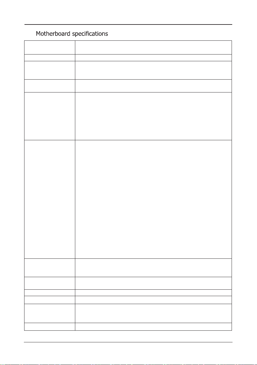
1.2
CPU
Chipet - Adopt Intel® H81 chipset
Memory
Expansion slots
Rear Panel I/O
Internal
Connectors
BIOS/POWER
Management
Audio
LAN
Form Factor
Working Environment
Operating system
- Support LGA1150 socket for Intel® 4th generation CoreTM i3/i5
/i7,Pentium®,Celeron® series processors
- 2 X 204-pin DDRIII SO-DIMM solts
- Support DDRIII SO-DIMM 1066/1333/1600MHz memory module
- The max memory capicity is up to 16GB
- 1 x MSATA slot
- 1 x MPCIE slot
- 1 x PJ1 power connector(DC Power)
- 1 x HDMI connector
- 1 x VGA connector
- 2 x USB 2.0 interfaces,backwards compatibility USB 1.1
- 2 x USB 3.0 interfaces,backwards compatibility USB 2.0/1.1
- 1 x RJ45 connector
- 2 x audio connectors(F_MIC/F_OUT)
- 1 x Optical digital audio interface (SPDIF)
- 1 x 4-pin ATX_12V power connector(JDCIN )
- 1 x 9-pinUSB2.0 headers for additional 2 USB 2.0 connectors
- 1 x 5-pinUSB2.0 headers for additional 1 USB 2.0 connector
- 2 x SATA3.0 connectors
- 2 x HDD_PWR connectors
- 1 x Front panel switches connector
- 1 x Front Panel audio connectors
- 2 x Fan connectors
- 1 x JLVDS jumper(Supports VGA and HDMI with
asynchronous display )
- 1 x 16-pin HDMI_CON connector
- 1 x 30-pin LVDS_CON connector
- 1 x 12-pin VGA_CON connector
- 1 x JGPIO connector
- 1 x JCOM1 connector
- 1 x Speakers connector
- 1 x 6_pin INVERTER1 connector
- 1 x JME jumper
- 1 x CLR_COMS jumper
- 1 x LCD_PWR jumper
-
Support advanced power management ACPI,Monitor CPU
temperture ,fan speed ,system voltage in real time
-
Wakeup By LAN, Power-on boot,watchdog function,etc.
-
Onboard 4 Channel HD Audio Codec
-
Front audio connector, Optical digital connector
-
1 x 10/100/1000Mbps NIC connector
-
Mini-ITX(170mm * 170mm) architecture
-
Working temperture :0~60
-
Working Moisture :5%~90% No Frost
-
Storage temperture :-20~70
-
Windows7/8/8.1/Linux
。
C
。
C
- 5 -

ECB-H81C11S User's Manual
1.3 Motherboard Layout
PJ 1
HDMI
VGA 1
USB1
LAN1
USB2
F_M IC
F_O UT
SPDIF1
SPEAKERS
JDCIN
OC_IMDH N
OC_AGV N
BAT
CLR_CMOS
JME
BIO S
FAUDIO
USB20_3
JCOM1
SATA1 SATA2
MSATA
MPCIE
HDD_PWR2
HDD_PWR1
DIMM2
DIMM1
FPANEL
CPU_FAN
SYS_FAN
L RWP_DC
VL OC_SD N
EVNI TR RE 11
LJ DV S
IPGJ O
FUSB1
(This picture is only for reference)
- 6 -

ECB-H81C11S User's Manual
1.4 Connecting Rear Panel I/O Devices
HDM LI AN
PJ 1
VGA
USB3.0
(This picture is only for reference)
• PJ1:
12V/19V DC Power interface
• HDMI:
• VGA:
• USB3.0(blue):
Connects to multimedia devices of HDMI protocol
Connects to a monitor's VGA input
USB3.0connector,backwards compatibility USB 2.0/1.1
• USB2.0(black):
USB2.0connector,backwards compatibility USB1.1
• LAN:
The LAN port allows the motherboard to connect to a local area network by means
of a network hub.
• F_MIC:
This jack is used to connect an external microphone
• F_OUT:
This jack is used to connect to the front left and right channel speakers of
the audio system
• SPDIF1:
This jack is Optical digital audio output interface ,which can be used to connect to
the front left and right channel speakers of the audio system
USB2.0
F_MIC
F_OUT SPDIF 1
- 7 -

ECB-H81C11S User's Manual
Chapter 2 Hardware Setup
Installing
2.1
It can block the transmission of electric RF, protect the internal components, and promote
after installing this panel. Before installing motherboard, you need to install this panel. If
2.2 Installing the Mainboard
Most computer chassis have a base with many mounting holes to allow the mainboard to
be securely attached, and at the same time, prevent the system from short circuits. There
are two ways to attach the mainboard to the
chassis base: (1) with studs, or (2) with spacers.
Basically, the best way to attach the board is with
studs. Only if you are unable to do this should you
attach the board with spacers. Line up the holes on
the board with the mounting holes on the chassis.
If the holes line up and there are screw holes, you
can attach the board with studs. If the holes line
up and there are only slots, you can only attach with
spacers. Take the tip of the spacers and insert them
into the slots. After doing this to all the slots, you can slide the board into position aligned
with slots. After the board has been positioned, check to make sure everything is OK before
putting the chassis back on.
Always power off the computer and unplug the AC power cord before adding or removing
any peripheral or component. Failing to do so may cause severe damage to your
mainboard and/or peripherals. Plug in the AC power cord only after you have carefully
checked everything.
To install this mainboard:
1. Locate all the screw holes on the mainboard and the chassis base.
2. Place all the studs or spacers needed on the chassis base and have them tightened.
3. Face the mainboard’s I/O ports toward the chassis’s rear panel.
4. Line up all the mainboard’s screw holes with those studs or spacers on the chassis.
5. Install the mainboard with screws and have them tightened.
2.3 Installation of the CPU and CPU Cooler
Before installing the CPU, please comply with the following conditions:
1. Please make sure that the mainboard supports the CPU.
2. Please take note of the one indented corner of the CPU. If you install the CPU in the wrong
direction, the CPU will not insert properly. If this occurs, please change the insert direction
of the CPU.
3. Please add an even layer of heat sink paste between the CPU and CPU cooler.
4. Please make sure the CPU cooler is installed on the CPU prior to system use, otherwise
overheating and permanent damage of the CPU may occur.
I/O Panel
it does not meet the required standards for the peripherals. If you wish to set the frequen-
- 8 -

ECB-H81C11S User's Manual
2.3.1 Installation of the CPU
1. Open the socket lever by
pushing the lever down and
away from the socket .
(These pictures are only for reference)
2. Lift the load p late and rem ove the plastic protective
socket cover. Do not touch the socket contacts and do not
discard the protective socket cover. Always replace with the
protective socket cover if the processor is being removed
from the socket.
3. Pos itio n the CPU o ve r
the socket, ensuring that
the gold triangle is on the
bottom-left corner of the
so cket, and then fit the
socket alignment keys into
the CPU notches. (marked
with circle)
2.3.2 Installation of the CPU Cooler
For proper installation, please kindly refer to the instruction manuals of your CPU Cooler.
4. Close the load plate, and then push down the load lever,
please ensure that the
UNDER the retention knob (marked with circle).
5. Insert the load lever under the retention tab.
front edge of the load plate slides
- 9 -

ECB-H81C11S User's Manual
2.4 Installing Memory Module
This motherboard provides two 204-pin DDRIII SO-DIMM slots.
Before starting the installation, please read the following warning messages:
2. Before installing or removing memory, make sure that the computer is turned off;
3. The memory is designed with fool-proof marker, if you insert with wrong direction, it can
not be inserted.
Installing memory:
1. Before installing or removing memory, please turn off the power and unplug the AC cable.
2. Carefully grasp both ends of memory, and do not touch the metal contacts.
3. Align the memory to slots, and pay attention to the direction.
4. Inclining 30 degrees and insert, then press down untill you hear the "clicking" sound (to
avoid any demage, your strengh must be gentle).
5. To remove the memory, push out both latch of DIMM slot at the same time, and take it
out.
Memory installation illustration (only for reference):
:Static will demage the electronic components of computer and memory, when doing
above step, you should contact with a grounded metial object to remove the static from your
body.
- 10 -
ECB-H81C11S User's Manual
OC_AGV N
OC_IMDH N
VL OC_SD N
EVNI TR RE 11
LJ DV S
IPGJ O
L RWP_DC
2.5 Connect with External Devices
2.5.1 Serial ATA Connectors
JDCIN
OC_IMDH N
OC_AGV N
CLR_CMOS
BAT
JME
FAUDIO
USB20_3
SATA1 SATA2
MSATA
BIOS
MPCIE
JCOM1
HDD_PWR2
HDD_PWR1
DIMM2
DIMM1
FPANEL
CPU_FAN
SYS_FAN
L RWP_DC
VL OC_SD N
The Serial ATA connectors can
connect to Serial ATA hardware
EVNI TR RE 11
or other corresponding devices
when use Serial ATA cable
LJ DV S
IPGJ O
FUSB1
。
PJ 1
HDMI
VGA1
USB1
LAN1
USB2
F_MIC
F_OU T
SPDIF1
SPEAKERS
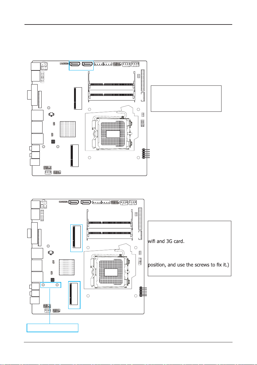
2.5.2 MSATA and MPCIE slots
JDCIN
BAT
JME
CLR_CMO S
FAUDIO
USB20_ 3
BIOS
JCOM1
PJ 1
HDMI
VGA1
USB1
LAN1
USB2
F_MIC
F_OUT
SPDIF1
SPEAKERS
Fix the screw antennas
SATA1 SATA2
MSATA
MPCIE
HDD_PWR2
HDD_PWR1
DIMM2
DIMM1
FPANEL
CPU_FAN
- 11 -
SYS_FAN
MSATA slot is long card, It supports
SSD.
MPCIE slot is long card ,It supports
(While installing, incline it 30 degrees
and insert,then press down to bolt
FUSB1

ECB-H81C11S User's Manual
OC_AGV N
OC_IMDH N
VL OC_SD N
EVNI TR RE 11
LJ DV S
IPGJ O
L RWP_DC
Chapter 3 Jumpers & Headers Setup
3.1 Checking Jumper Settings
• 2-pin jumper: Plug the jumper cap onto both
pins will make it CLOSE (SHORT). Remove the
cap or plug it on another pins (keep for future
use) will activate the jumper.
• 3-pin jumper: Plug the jumper cap onto pin
1~2 or pin 2~3 will make it CLOSE (SHORT).
shorted by plugging the jumper cap in.
How to identify the PIN1?
Please check the Motherboard carefully, the PIN1
is marked by "1", white thick line or white triangle.
3.2 CMOS Memory Clearing Header(JBAT)
When: (a) the CMOS data demaged, (b) you forgot the supervisor or password of BIOS,
(c) you are unable to boot-up because the frenquency of CPU was incorrectly, or (d) there
have modifications on CPU or memory modules, means you need to unplug the CMOS
header.
It uses a jumper cap to clear the CMOS setup, and reset the BIOS value to default.
• Pins 1 and 2 open circuit (Default): Normal situation
• Pins 1 and 2 shorted: Clear CMOS setup
HDMI
JDCIN
PJ 1
USB20_3
SATA1 SATA2
HDD_PWR2
HDD_PWR1
FPANEL
CPU_FAN
SYS_FAN
To clear the CMOS setup and set to default values:
1. Power off the system.
2. Plug the jumper cap to pin 1-2, and wait for 3-5 seconds, then plug the cap back to pin
1-2.
3. Power on the system.
4. If the frequency of CPU set incorrect, please press the <Del> button to enter the BIOS
setup menu after powering on system.
5. Reset the running speed of CPU to default or to suitable value.
6. Save and exit the BIOS setup menu.
- 12 -
VGA1
F_MIC
F_OUT
SPDIF1
USB1
LAN1
USB2
SPEAKERS
BAT
JME
CLR_CMO S
FAUDIO
DIMM2
DIMM1
MSATA
BIOS
MPCIE
JCOM1
FUSB1

ECB-H81C11S User's Manual
3.3 Jumpers setting
JME Jumper
pin
1-2 Pin Update ME
2-3 Pin No Update ME
LCD_PWR Jumper
pin
1-2 3.3V
3-4 5V
5-6 12V
3.4 Front Panel Switches & Indicators Headers
JDCIN
OC_AGV N
OC_IMDH N
BAT
CLR_CMOS
JME
FAUDIO
USB20_3
SATA1 SATA2
MSATA
BIOS
MPCIE
JCOM1
HDD_PWR2
HDD_PWR1
DIMM2
DIMM1
FPANEL
CPU_FAN
SYS_FAN
L RWP_DC
VL OC_SD N
EVNI TR RE 11
LJ DV S
IPGJ O
FUSB1
PJ 1
HDMI
VGA1
USB1
LAN1
USB2
F_MIC
F_OUT
SPDIF1
SPEAKERS
1
2
2
1
HDLED
PWR_LED
+ -
+ -
PWRLED
HD_LED
GND
GND
PWR_ON
PWRBTN#
RST
RESET
GND
HD_LED : Hard Driver LED connector
hard drive(s) is/are being accessed.
RST : Reset Switch
This connector connects to the case-mounted reset switch which allows you to reboot without
having to power-off the system and thus prolonging the life of the power supply or system.
PWR_ON : Power Switch
Depending on the setting in the BIOS setup, this switch serves two functions which will allow
you to power-on/off the system or to enter the suspend mode.
PWR_LED : Power/Standby LED
When the system's power is on, this LED will light.When the system is in the S1 (POS - Power
on Suspend) or S3 (STR - Suspend to RAM, optional) state,it will blink every second.
9
10
10
9
eht nehw thgil lliw DEL eht dna,elbac DEL DH detnuom-esac eht ot stcennoc rotcennoc sihT
- 13 -

ECB-H81C11S User's Manual
OC_AGV N
OC_IMDH N
VL OC_SD N
EVNI TR RE 11
LJ DV S
IPGJ O
L RWP_DC
OC_AGV N
OC_IMDH N
VL OC_SD N
EVNI TR RE 11
LJ DV S
IPGJ O
L RWP_DC
3.5 FUSB1 and USB20_3 extended interfaces
JDCIN
BAT
JME
CLR_CMOS
FAUDIO
USB20_3
SATA1 SATA2
HDD_PWR2
HDD_PWR1
FPANEL
CPU_FAN
SYS_FAN
through USB bracket, FUSB1 can provide two USB
ports, USB20_3 can pick out a USB port. USB bracket
for optional accessories, you can contact the local
dealer.
FUSB1
DIMM2
DIMM1
MSATA
pin pin
1 VCC 2 VCC
3 DATA- 4 DATA-
BIOS
FUSB1
5 DATA+ 6 DATA+
7 GND 8 GND
9 NC 10 GND
USB20_3
MPCIE
JCOM1
pin pin
1 VCC 2 USBP10N
3 USBP10P 4 GND
5 NC
PJ 1
HDMI
VGA1
USB1
LAN1
USB2
F_MIC
F_OUT
SPDIF1
SPEAKERS
HDD_PWR1/2(SATA POWER Interface) and JDCIN(DC POWER Interface)
3.6
JDCIN
BAT
JME
CLR_CMOS
FAUDIO
USB20_3
SATA1 SATA2
MSATA
BIOS
MPCIE
JCOM1
HDD_PWR2
HDD_PWR1
DIMM2
DIMM1
FPANEL
CPU_FAN
PJ 1
HDMI
VGA1
USB1
LAN1
USB2
F_MIC
F_OUT
SPDIF1
SPEAKERS
By the power socket,the power supply
SYS_FAN
can provide power that is enough and
stable for all the components on the
mainboard.
Before inserting into the power
soc ket,please make be sure that the
power of power supply has been turned
off ,and allthe components and devices
protection design,After confirming that
the direction is right ,you can insert.
FUSB1
pin pin
1 12V 2 GND
3 GND 4 5V
- 14 -
ECB-H81C11S User's Manual
OC_AGV N
OC_IMDH N
VL OC_SD N
EVNI TR RE 11
LJ DV S
IPGJ O
L RWP_DC
OC_AGV N
OC_IMDH N
VL OC_SD N
EVNI TR RE 11
LJ DV S
IPGJ O
L RWP_DC
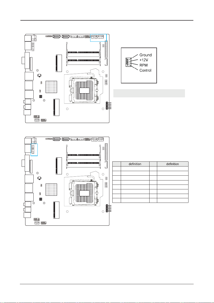
3.7 FAN Power Connectors
JDCIN
PJ 1
HDMI
USB20_3
SATA1 SATA2
HDD_PWR2
HDD_PWR1
FPANEL
CPU_FAN
SYS_FAN
VGA1
MSATA
BIOS
MPCIE
JCOM1
F_MIC
F_OUT
SPDIF1
USB1
LAN1
USB2
SPEAKERS
BAT
JME
CLR_CMOS
FAUDIO
3.8 HDMI_CON Connector
JDCIN
BAT
JME
CLR_CMOS
FAUDIO
USB20_3
SATA1 SATA2
MSATA
BIOS
MPCIE
JCOM1
PJ 1
HDMI
VGA1
USB1
LAN1
USB2
F_MIC
F_OUT
SPDIF1
SPEAKERS
HDD_PWR2
HDD_PWR1
DIMM2
DIMM1
DIMM2
DIMM1
FPANEL
Note:These fan connectors are not jumpers. DO NOT
place jumper caps on these connectors.
FUSB1
SYS_FAN
CPU_FAN
pin pin
1 HDMIC_TX2_DP 2 HDMIC_SCL
3 HDMIC_TX2_DN 4 HDMIC_SDA
5 HDMIC_TX1_DP 6 GND
7 HDMIC_TX1_DN 8 DPC_HPD_CN
9 HDMIC_TX0_DP 10 DAC_5V
11 HDMIC_TX0_DN 12 GND
13 HDMIC_CLK_DP 14 GND
15 HDMIC_CLK_DN 16 GND
FUSB1
- 15 -

ECB-H81C11S User's Manual
OC_AGV N
OC_IMDH N
VL OC_SD N
EVNI TR RE 11
LJ DV S
IPGJ O
L RWP_DC
OC_AGV N
OC_IMDH N
VL OC_SD N
EVNI TR RE 11
LJ DV S
IPGJ O
L RWP_DC
3.9 VGA_CON Connector
JDCIN
PJ 1
HDMI
USB20_3
SATA1 SATA2
HDD_PWR2
HDD_PWR1
FPANEL
CPU_FAN
SYS_FAN
VGA1
USB1
BAT
JME
LAN1
F_MIC
F_OUT
SPDIF1
USB2
SPEAKERS
CLR_CMOS
FAUDIO
MSATA
BIOS
MPCIE
JCOM1
DIMM2
DIMM1
pin pin
FUSB1
3.10 LVDS_CON Connector(Display Port)
JDCIN
BAT
JME
CLR_CMOS
FAUDIO
USB20_3
SATA1 SATA2
HDD_PWR2
HDD_PWR1
FPANEL
CPU_FAN
SYS_FAN
pin pin
1 LCDVDD 2 LCDVDD
3 LCDVDD 4 GND
5 GND 6 GND
7 LVDSA_DATA0N 8 LVDSA_DATA0P
9 LVDSA_DATA1N 10 LVDSA_DATA1P
11 LVDSA_DATA2N 12 LVDSA_DATA2P
13 GND 14 GND
15 LVDSA_CLKN 16 LVDSA_CLKP
MSATA
DIMM2
DIMM1
17 LVDSA_DATA3N 18 LVDSA_DATA3P
19 LVDSB_TX0N 20 LVDSB_TX0P
21 LVDSB_TX1N 22 LVDSB_TX1P
BIOS
23 LVDSB_TX2N 24 LVDSB_TX2P
25 GND 26 GND
FUSB1
27 LVDSB_CLKN 28 LVDSB_CLKP
29 LVDSB_TX3N 30 LVDSB_TX3P
MPCIE
JCOM1
PJ 1
HDMI
VGA1
USB1
LAN1
USB2
F_MIC
F_OUT
SPDIF1
SPEAKERS
1 GND 2 5V_VSYNC
3 5V_HSYNC 4 GND
5 VGA_R 6 GND
7 VGA_G 8 GND
9 VGA_B 10 GND
11 5V_DDCA_DATA 12 5V_DDCA_CLK
- 16 -

ECB-H81C11S User's Manual
OC_AGV N
OC_IMDH N
VL OC_SD N
EVNI TR RE 11
LJ DV S
IPGJ O
L RWP_DC
OC_AGV N
OC_IMDH N
VL OC_SD N
EVNI TR RE 11
LJ DV S
IPGJ O
L RWP_DC
3.11 INVERTER1 Connector
JDCIN
PJ 1
HDMI
USB20_3
SATA1 SATA2
HDD_PWR2
HDD_PWR1
FPANEL
CPU_FAN
SYS_FAN
VGA1
USB1
BAT
JME
LAN1
CLR_CMOS
USB2
F_MIC
F_OUT
SPDIF1
SPEAKERS
FAUDIO
BIOS
MPCIE
JCOM1
3.12 JLVDS Connector
JDCIN
BAT
JME
CLR_CMOS
FAUDIO
USB20_3
SATA1 SATA2
BIOS
MPCIE
JCOM1
PJ 1
HDMI
VGA1
USB1
LAN1
USB2
F_MIC
F_OUT
SPDIF1
SPEAKERS
MSATA
MSATA
HDD_PWR2
HDD_PWR1
DIMM2
DIMM1
DIMM2
DIMM1
FPANEL
pin pin
1 IVT_VCC 2 IVT_VCC
3 PNON 4 BKLT_PWM1
5 GND 6 GND
FUSB1
SYS_FAN
CPU_FAN
JLVDS
pin pin
1 GND 2 GND
3 RLV_CFG 4 RLV_LNK
5 GND 6 NC
JLVDS jumper setting
pin
FUSB1
NC 6 BIT
1-3 8 BIT JEIDA
3-5 8 BIT VESA
2-4 NC DUAL LINK LVDS
2-4 CLOSE SINGLE LINK LVDS
- 17 -

ECB-H81C11S User's Manual
OC_AGV N
OC_IMDH N
VL OC_SD N
EVNI TR RE 11
LJ DV S
IPGJ O
L RWP_DC
OC_AGV N
OC_IMDH N
VL OC_SD N
EVNI TR RE 11
LJ DV S
IPGJ O
L RWP_DC
3.13 JGPIO Connector
JDCIN
PJ 1
HDMI
USB20_3
SATA1 SATA2
HDD_PWR2
HDD_PWR1
FPANEL
CPU_FAN
SYS_FAN
VGA1
MSATA
BIOS
MPCIE
JCOM1
F_MIC
F_OUT
SPDIF1
USB1
LAN1
USB2
SPEAKERS
BAT
JME
CLR_CMOS
FAUDIO
3.14 Front Panel Audio Connector
JDCIN
BAT
JME
CLR_CMOS
FAUDIO
USB20_3
SATA1 SATA2
BIOS
MPCIE
JCOM1
HDD_PWR2
MSATA
1 PORT1L Microphone_Left Microphone
2 AGND Ground Ground
3 PORT1R Microphone_Right MIC Power
4 PRESENCE# -ACZ_DET N/A
5 PORT2R Line2_Right Line out (R)
6 SENSE1_RETURN AuD_R_Return N/A
7 SENSE_SEND FAUDIO_JD N/A
8 No Pin N/A N/A
9 PORT2L Line2_Left Line Out(L)
10 SENSE2_RETURN AuD_L_Return N/A
PJ 1
HDMI
VGA1
USB1
LAN1
USB2
F_MIC
F_OUT
SPDIF1
SPEAKERS
Pin No. Header
HDD_PWR1
DIMM2
DIMM1
DIMM2
DIMM1
FPANEL
pin pin
1 GPI_1+ 2 GPI_1+
3 GPI_2+ 4 GPI_2+
5 GPI_3+ 6 GPI_3+
7 GPI_4+ 8 GPI_4+
9 GND 10 GND
FUSB1
SYS_FAN
CPU_FAN
FUSB1
- 18 -

ECB-H81C11S User's Manual
OC_AGV N
OC_IMDH N
VL OC_SD N
EVNI TR RE 11
LJ DV S
IPGJ O
L RWP_DC
OC_AGV N
OC_IMDH N
VL OC_SD N
EVNI TR RE 11
LJ DV S
IPGJ O
L RWP_DC
3.15 SPEAKERS Connector
JDCIN
PJ 1
HDMI
USB20_3
SATA1 SATA2
HDD_PWR2
HDD_PWR1
FPANEL
CPU_FAN
SYS_FAN
VGA1
USB1
BAT
JME
LAN1
CLR_CMOS
USB2
F_MIC
F_OUT
SPDIF1
SPEAKERS
FAUDIO
BIOS
MPCIE
JCOM1
3.16 JCOM1 Connector
JDCIN
BAT
JME
CLR_CMOS
FAUDIO
USB20_3
SATA1 SATA2
MSATA
BIOS
MPCIE
JCOM1
PJ 1
HDMI
VGA1
USB1
LAN1
USB2
F_MIC
F_OUT
SPDIF1
SPEAKERS
MSATA
HDD_PWR2
HDD_PWR1
DIMM2
DIMM1
DIMM2
DIMM1
FPANEL
The SPEAKERS is audio output for 3W
be not output.
pin pin
1 Right + 2 Right -
FUSB1
SYS_FAN
CPU_FAN
FUSB1
3 Left- 4 Left+
pin pin
1 DCD 2 RXD
3 TXD 4 DTR
5 GND 6 DSR
7 RTS 8 CTS
9 RI
- 19 -

ECB-H81C11S User's Manual
Chapter 4 BIOS Setup Utility
BIOS stands for Basic Input and Output System. It was once called ROM BIOS when it was
stored in a Read-Only Memory (ROM) chip. Now manufacturers would like to store BIOS in
EEPROM which means Electrically Erasable Programmable Memory. BIOS used in this series
of mainboard is stored in EEPROM, and is the first program to run when you turn on your
computer.
BIOS performs the following functions:
1. Initializing and testing hardware in your computer (a process called "POST", for Power On
Self Test).
2. Loading and running your operating system.
3. Helping your operating system and application programs manage your PC hardware by
means of a set of routines called BIOS Run-Time Service.
4.1 About BIOS Setup
BIOS Setup is an interactive BIOS program that you need to run when:
1. Changing the hardware of your system. (For example: installing a new Hard Disk etc.)
2. Modifying the behavior of your computer. (For example: changing the system time or date,
or turning special features on or off etc.)
3. Enhancing your computer's behavior. (For example: speeding up performance by turning
on shadowing or cache)
4.2 To Run BIOS Setup
First access BIOS setup menu by pressing <F1> key after “POST” is complete (before OS is
will be pressed if you will enter BIOS setup menu.
4.3 About CMOS
CMOS is the memory maintained by a battery. CMOS is used to store the BIOS settings you
have selected in BIOS Setup. CMOS also maintains the internal clock. Every time you turn
on your computer, the BIOS Looks into CMOS for the settings you have selected and
be lost and POST will issue a “CMOS invalid” or “CMOS checksum invalid” message. If this
new start.
4.4 The POST (Power On Self Test)
POST is an acronym for Power On Self Test. This program will test all things the BIOS does
before the operating system is started. Each of POST routines is assigned a POST code, a
unique number which is sent to I/O port 080h before the routine is executed.
- 20 -

ECB-H81C11S User's Manual
4.5 BIOS Setup — CMOS Setup Utility
•
In order to increase system stability and performance, our engineering staff is
constantly improving the BIOS menu. The BIOS setup screens and descriptions
illustrated in this manual are for your reference only, and may not completely
match with what you see on your screen.This chapter were based mainly on
the model, unless specif cally stated.
•
Do not change the BIOS parameters unle
ss you fully understand its function.
4.5.1 CMOS Setup Utility
After powering up the system, the BIOS message appears on the scr
or when CMOS setting wrong, there is following message appears on the screen , but if
pressed if you will enter BIOS setup menu.
Press <DEL> to enter SETUP
If this message disappears before you respond, restart the system by pressing <Ctrl> +
<Alt>+ <Del> keys, or by pressing the reset button on computer chassis. Only when these
two methods should be fail that you restart the system by powering it off and then back on.
After pressing <Del> key, the main menu appears.
Aptio Setup Utility - Copyright (C) 2012 American Megatrends,Inc.
Main Advanced Chipset Boot Security
BIOS Information
BIOS Vendor American Megatrends
Core Version 4.6.5.4
Compliancy UEFI 2.3.1;PI 1.2
Project Version SK12E 0.22 x64
Build Date and Time 04/04/2014 10:53:21
System Language [English]
System Date [Tue 04/15/2014]
System Time [13:15:53]
Access Level Administrator
Version 2.15.1236. Copyright (C) 2012 American Megatrends, Inc.
The menu bar on top of the screen has the following main items:
Main
Advanced For changing the advanced system settings.
Chipset
Boot
Security For changing the system security setttings.
For changing the system ports settings.
Choose the system default
language
: Select Screen
→←
↑↓
: Select Item
Enter: Select
+/-: Change Opt.
F1: General Help
F2: Previous Values
F9: Optimized Defaults
F10: Save & Exit
ESC: Exit
- 21 -

ECB-H81C11S User's Manual
4.5.2 Control Keys
Press <F1> to pop up a small help window that describes the appropriate keys
to use and the available options for the highlighted item.
Please check the following table for the function description of each control key.
Control Key(s) Function Description
/
←
→
↑
/ ↓
+/
- To Change option for the selected items
<Enter> To bring up the selected screen
<ESC>
<F1> General help
<F2> Previous Values
<F3> Optimal Defaults
<F4> Save & exit
<F9> Load Optimal Defaults
<F10>
Move cursor left or right to select screens
Move cursor up or down to select items
Main Menu - Quit and not save changes into CMOS Status
Page Setup Menu and Option Page Setup Menu - Exit
current page and return to Main Menu
- 22 -

ECB-H81C11S User's Manual
4.5.3 Main
BIOS Information
BIOS Vendor American Megatrends
Core Version 4.6.5.4
Compliancy UEFI 2.3.1;PI 1.2
Project Version SK12E 0.22 x64
Build Date and Time 04/04/2014 10:53:21
System Language [English]
System Date [Tue 04/15/2014]
System Time [13:15:53]
Access Level Administrator
·
BIOS Information
This page mainly introduce the BIOS related information, such as the BIOS version,
the BIOS manufacturer, the program code versions, establish dates, etc.
·
System Language
Allows you to choose the system default language.
·
System Date
Allows you to set the syetem date. The format is "Day/Month/Date/Year."
· System Time
Allows you to set the syetem date. The format is "hour/minute/second."
Aptio Setup Utility - Copyright (C) 2012 American Megatrends,Inc.
Main Advanced Chipset Boot Security
Choose the system default
language
: Select Screen
→←
↑↓
: Select Item
Enter: Select
+/-: Change Opt.
F1: General Help
F2: Previous Values
F9: Optimized Defaults
F10: Save & Exit
ESC: Exit
Version 2.15.1236. Copyright (C) 2012 American Megatrends, Inc.
4.5.4 Advanced
Main Advanced Chipset Boot Security
Serial ATA Port 1 Empty
Serial ATA Port 2 Empty
MSATA Port Empty
►
ACPI Settings
►
Onboard Device Configuration
►
CPU Configuration
►
Intel(R) Rapid Start Technology
►
PCH-FW Configuration
►
Advanced Power Management
►
Super IO Configuration
►
HW Monitor
Aptio Setup Utility - Copyright (C) 2012 American Megatrends,Inc.
Version 2.15.1236. Copyright (C) 2012 American Megatrends, Inc.
- 23 -
Control the execution
of UEFI and Legacy
PXE OpROM
: Select Screen
→←
↑↓
: Select Item
Enter: Select
+/-: Change Opt.
F1: General Help
F2: Previous Values
......
ECB-H81C11S User's Manual
►
ACPI Settings Press<Enter>key to turn into the submenu
Aptio Setup Utility - Copyright (C) 2012 American Megatrends,Inc.
Advanced
ACPI Settings
Enable ACPI Auto Configuration [Disabled]
Enable Hibernation [Enabled]
S3 Video Repost [Disabled]
ACPI Sleep State [S3 only...]
• Enable ACPI Auto Conf guration
Version 2.15.1236. Copyright (C) 2012 American Megatrends, Inc.
Enables or Disables BIOS
....
: Select Screen
→←
↑↓
: Select Item
Enter: Select
+/-: Change Opt.
F1: General Help
......
• Enable Hibernation
Enables or disables system ability to hibernate (OS/S4 sleep state). This option may be not
effective with some OS,options: Enabled, Disabled.
• S3 Video Repost
Enables or disables S3 Video Repost. Options: Enabled, Disabled.
• ACPI Sleep State
Select the highest ACPI sleep state the system will enter when the suspend button is pressed.
Optional for Suspend Disabled,S1 (CPU Stop Clock),S3 only(Suspend to RAM).
Press < ESC> key to return to the Advanced menu
►
Onboard Device Conf guration Press<Enter>key to turn into the submenu
Aptio Setup Utility - Copyright (C) 2012 American Megatrends,Inc.
Advanced
Onboard Lan Control(Port6) [Enabled]
Launch PXE OpROM policy [Disabled]
Launch Storage OpROM policy [Enabled]
HD Audio Controller [Enabled]
Azalia Internal HDMI Codec [Enabled]
USB Audio Controller [Enabled]
USB Controller
►
USB Configuration
PCI Device List [Disabled]
Version 2.15.1236. Copyright (C) 2012 American Megatrends, Inc.
• Onboard Lan Control (Port6)
Setting Lan open and close, options: Enabled, Disabled.
• Launch PXE OpROM policy
Controls the execution of UEFI and Legacy PXE OpROM, options: Enabled, Disabled.
• Launch Storage OpROM policy
Setting old equipment storage ROM open and close, options: Enabled, Disabled.
Onboard Lan Control
: Select Screen
→←
↑↓
: Select Item
Enter: Select
+/-: Change Opt.
F1: General Help
......
- 24 -

ECB-H81C11S User's Manual
• HD Audio Controller
Setting HD audio functions, options: Enabled, Disabled.
• Azalia Internal HDMI Codec
HDMI Audio controller, options: Enabled, Disabled.
• USB Audio Controller
Onboard USB Audio Controller, options: Enabled, Disabled.
• USB Controller
Controls of USB ports,options: Enabled, Disabled.
• PCI Device List
Check out PCI Devices,options: Enabled, Disabled.
Press < ESC> key to return to the Advanced menu
►
USB Conf guration Press<Enter>key to turn into the submenu
Aptio Setup Utility - Copyright (C) 2012 American Megatrends, Inc.
Advanced
USB Configuration
Enables Legacy USB...
USB Module Version 8.10.27
USB Devices:
1 Keyboard, 2 Hubs
Legacy USB Support [Enabled]
XHCI Hand-off [Enabled]
EHCI Hand-off [Disabled]
USB Mass Storage Device Support [Enabled]
USB hardware delays and time-outs:
USB transfer time-out [20 sec]
Device reset time-out [20 sec]
Device power-up delay [Auto]
• Legacy USB Support
Setting support old input/output devices, such as the mouse, keyboard etc, options:
Enabled,Disabled,Auto.
• XHCI Hand-off
Setting XHCI Hand-Off function, options: Enabled,Disabled.
• EHCI Hand-off
Setting EHCI Hand-Off function, options: Enabled,Disabled.
• USB Mass Storage Driver Support
Enable/Disable USB Storage Driver Support,options: Enabled,Disabled.
• USB transfer time-out
Optional for 1 sec,5 sec,10 sec,20 sec .
• Device reset time-out
Optional for 10 sec,20 sec,30 sec,40 sec.
• Device power-up delay
Optional for Auto,Manual.
Press < ESC> key to return to the Advanced menu
Version 2.15.1236. Copyright (C) 2012 American Megatrends, Inc.
: Select Screen
→ ←
↑↓: Select Item
Enter: Select
+/-: Change Opt.
F1: General Help
F7: Previous Values
.......
- 25 -

ECB-H81C11S User's Manual
►
CPU Conf guration Press<Enter>key to turn into the submenu
Aptio Setup Utility - Copyright (C) 2012 American Megatrends,Inc.
Advanced
CPU configuration
Intel(R) Core(TM) i3-4130 CPU @ 3.40GHz
CPU Signature 306c3
Processor Family 6
Microcode Patch 12
FSB Speed 100 MHz
Max CPU Speed 3400 MHz
Min CPU Speed 800 MHz
CPU Speed 3400 MHz
Processor Cores 2
L1 Data Cache 32 kB x 2
L1 Code Cache 32 kB x 2
L2 Cache 256 kB x 2
L3 Cache 3072 kB
Hyper-Threading [Enabled]
Active Processor Cores [All]
Limit CPUID Maximum [Disabled]
Execute Disable Bit [Enabled]
Internal Virtualization Technology [Enabled]
Enhanced C1 state [Enabled]
CPU C3 Report [Disabled]
CPU C6 report [Disabled]
C6 Latency [Short]
CPU C7 report [Disabled]
C7 Latency [Long]
Version 2.15.1236. Copyright (C) 2012 American Megatrends, Inc.
Enable for Windows XP
and Linux.When Disabled
only one thread per
enabled core is enabled.
: Select Screen
→←
↑↓
: Select Item
Enter: Select
+/-: Change Opt.
F1: General Help
F2: Previous Values
F9: Optimized Defaults
F10: Save & Exit
ESC: Exit
frequency,64-bit support, max/min frequency, stepping, microcode version, code number and
hyper-threading technology support, etc.
• Hyper-threading
The Intel Hyper-threading Technology allows a hyper-threading processor to appear as
two logical processors to the operating system.when disabled,only one thread per
enabled core is enabled.options: Enabled,Disabled.
• Active Processor Core
Use this item to select the number of cores to enable in each processor package.
enabled core is enabled.options: ALL,1.
• Limit CPUID Maxinum
Set limits maximum CPUID, options: Enabled, Disabled.
• Execute Disble Bit
Setting bits operation, options: Enabled, Disabled.
• Intel Virtualization Technology
When this function is enabled,it allows a VMMto utilize the additional hardware
capabilities provided by Intel Virtualization Technology.Options: Enabled, Disabled.
• Enhanced C1 state
This item should be enabled in order to enable the enhanced Halt State
options: Enabled, Disabled.
.
- 26 -

ECB-H81C11S User's Manual
• CPU C3 Report
Setting CPU C3 report to OS, options: Enabled, Disabled.
• CPU C6 Report
Setting CPU C6 report to OS, options: Enabled, Disabled.
• C6 Latency
• CPU C7 Report
Setting CPU C7 report to OS, options: Enabled, Disabled.
• C7 Latency
Press < ESC> key to return to the Advanced menu
►
Intel(R) Rapid Start Technology Press<Enter>key to turn into the submenu
Aptio Setup Utility - Copyright (C) 2012 American Megatrends,Inc.
Advanced
Intel(R) Rapid Start Technology [Disabled] Enable or disable
Version 2.15.1236. Copyright (C) 2012 American Megatrends, Inc.
This item allows you to Enable or Disable Intel(R) Rapid Start Technology, options: Enabled,
Disabled.
►
PCH-FW Conf guration Press<Enter>key to turn into the submenu
Aptio Setup Utility - Copyright (C) 2012 American Megatrends,Inc.
Advanced
ME FW Version 9.0.12.1397
ME Firmware Mode Normal Mode
ME Firmware Type Full Sku Firmware
MDES BIOS Status Code [Disabled]
►
Firmware Update Configuration
Version 2.15.1236. Copyright (C) 2012 American Megatrends, Inc.
• MDES BIOS Status Code
Setting MDES BIOS Status Code open/close,options:Enabled,Disabled.
options: Enabled, Disabled.
options: Enabled, Disabled.
Intel(R) Rapid Start
Technology
: Select Screen
→←
↑↓
: Select Item
Enter: Select
+/-: Change Opt.
F1: General Help
......
Enable/Disable MDES BIOS
Status Code.
: Select Screen
→←
↑↓
: Select Item
Enter: Select
+/-: Change Opt.
F1: General Help
......
Code
- 27 -
ECB-H81C11S User's Manual
►
Firmware Update Conf guration Press<Enter>key to turn into the submenu
Aptio Setup Utility - Copyright (C) 2012 American Megatrends,Inc.
Advanced
Me FW Image Re-Flash [Disabled] Enable/Disable Me FW
Image Re-Flash function.
: Select Screen
→←
↑↓
: Select Item
Enter: Select
+/-: Change Opt.
F1: General Help
......
Version 2.15.1236. Copyright (C) 2012 American Megatrends, Inc.
• Me FW Image Re-Flash
Me FW Image Re-Flash function.options:Enabled,Disabled.
Press < ESC> key to return to the Advanced menu
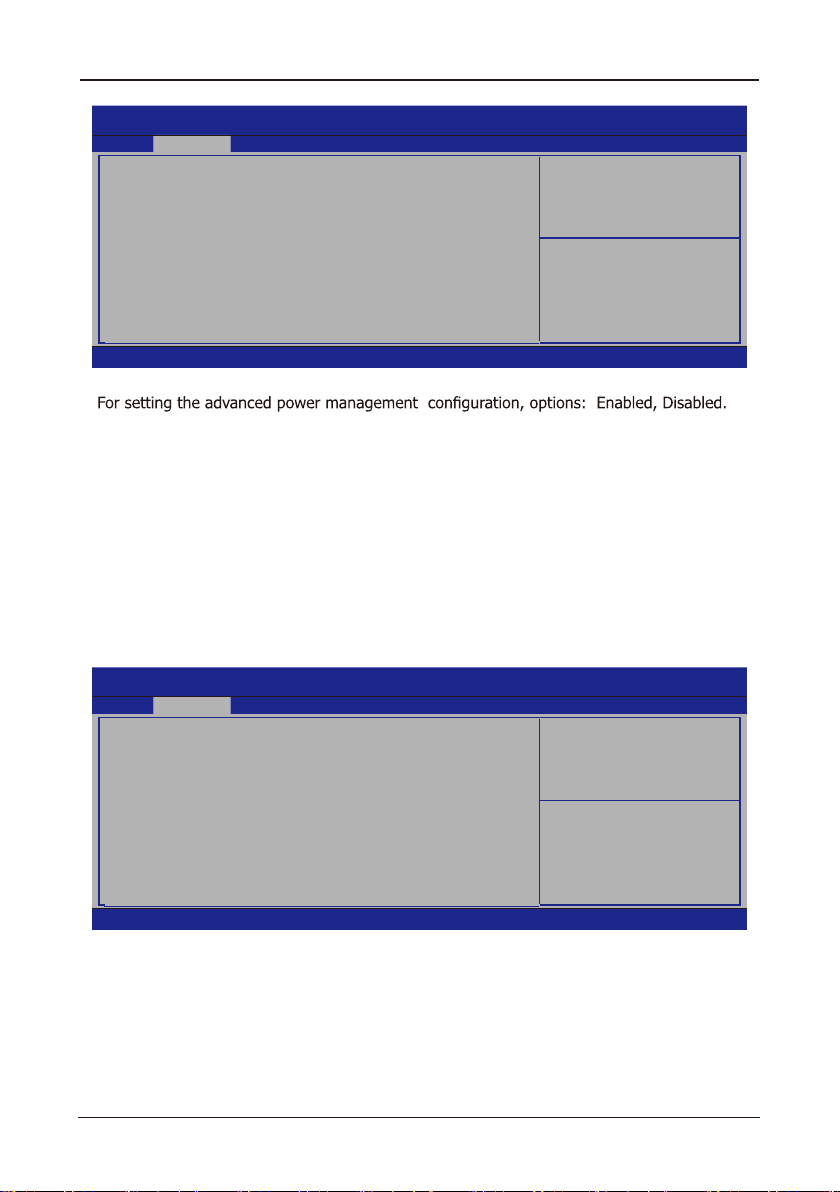
►
Advanced Power Management Press<Enter>key to turn into the submenu
Aptio Setup Utility - Copyright (C) 2012 American Megatrends,Inc.
Advanced
Advanced Power Management
AC Power Loss [Power On]
USB KB/MS Wakeup [Disabled]
Lan Wakeup [Enabled]
Wakeup by RTC [Disabled]
Version 2.15.1236. Copyright (C) 2012 American Megatrends, Inc.
• AC Power Loss
Setting the system power state after a powre failure. Setting "Power Off", need to press
the case power button to boot again. Setting "Power On", the system will power up itself
when the power is back. Setting to "Last State", the system will resume its last state
before the power loss.
The default value is "Power Off".
• USB KB/MS WakeUp
USB KB/MS WakeUp,for S3/S4. Options: Enabled, Disabled.
• Lan Wakeup
Network control of awakening. Options: Enabled, Disabled.
• Wakeup By RTC
Setting boot waking up time(day,hr:min:sec). optional for Disabled,Enabled.
Press < ESC> key to return to the Advanced menu
AC Power Loss
: Select Screen
→←
↑↓
: Select Item
Enter: Select
+/-: Change Opt.
F1: General Help
......
- 28 -

ECB-H81C11S User's Manual
►
Super IO Conf guration Press<Enter>key to turn into the submenu
Aptio Setup Utility - Copyright (C) 2012 American Megatrends, Inc.
Advanced
Super IO Configuration
NCT5532D Super IO Chip NCT5532D
►
Serial Port 0 Configuration
Version 2.15.1236. Copyright (C) 2012 American Megatrends, Inc.
►
Serial Port0 Conf guration Press<Enter>key to turn into the submenu
Aptio Setup Utility - Copyright (C) 2012 American Megatrends, Inc.
Advanced
Serial Port 0 Configuration
Serial Port [Enabled]
Device Settings IO=3F8h; IRQ=4
Change Settings [Auto]
Set P aram ete rs o f
Serial Port0(COMA)
: Select Screen
→ ←
↑↓: Select Item
Enter: Select
+/-: Change Opt.
F1: General Help
F7: Previous Values
.......
Enable o r D isab l e
Serial Port(COM)
: Select Screen
→ ←
↑↓: Select Item
Enter: Select
+/-: Change Opt.
F1: General Help
F7: Previous Values
.......
Version 2.15.1236. Copyright (C) 2012 American Megatrends, Inc.
• Serial Port
Setting the serial port function, options: Enabled, Disabled.
• Change Settings
Press < ESC> key to return to the Advanced menu
- 29 -

ECB-H81C11S User's Manual
►
H/W Monitor Press<Enter>key to turn into the submenu
Aptio Setup Utility - Copyright (C) 2012 American Megatrends, Inc.
Advanced
Pc Health Status
System temperature : +29 °C
CPU Temperature : +39 °C
SysFan Speed : N/A
CPUFan Speed : 1985 RPM
CPU Voltage : +1.768 V
CPU Core Voltage : +1.116 V
Memory Voltage : +1.528 V
PCH 1.05V : +1.072 V
VCC3V : +3.360 V
VBAT : +3.296 V
CPU SmartFan [Disabled]
PWM Output 100
Version 2.15.1236. Copyright (C) 2012 American Megatrends, Inc.
The hardware monitoring page showing the current system working state, including the CPU
temperature, system temperature, fan speed and voltage readings, etc.
• CPU SmartFan
This item allows you to enable or disable the CPU smartfan function.
Options: Enabled, Disabled.
• PWM Output
This item allows you to adjust the speed of fans.
Press < ESC> key to return to the Advanced menu
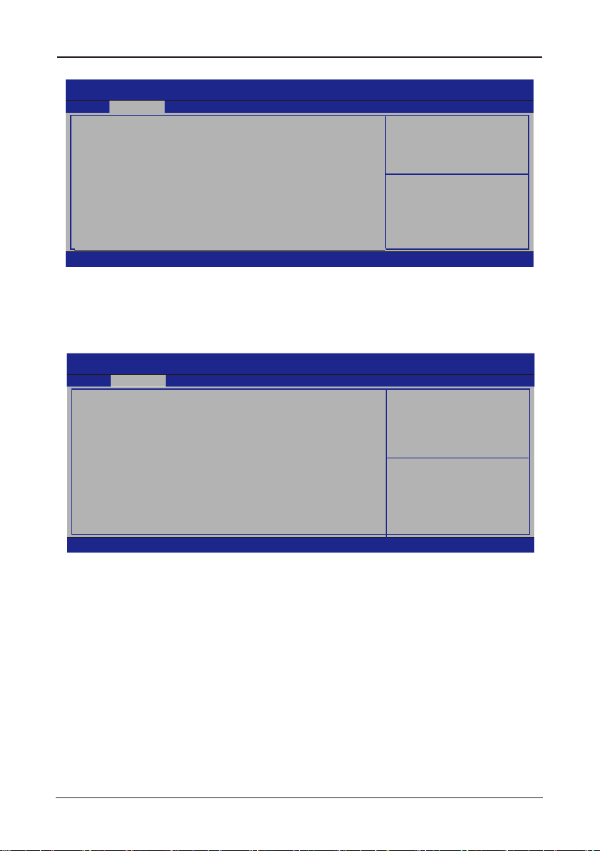
4.5.5 Chipset
Main Advanced Chipset Boot Security
►
SouthBridge Configuration
►
NorthBridge Configuration
Aptio Setup Utility - Copyright (C) 2012 American Megatrends, Inc.
Enable or......
:Select Screen
→ ←
↑↓:Select Item
Enter: Select
+/-:Change Opt.
F1:General Help
F7:Previous Values
......
PCH Parameters
: Select Screen
→ ←
↑↓
: Select Item
Enter: Select
+/-: Change Opt.
F1: General Help
F7: Previous Values
......
Version 2.15.1236. Copyright (C) 2012 American Megatrends, Inc.
- 30 -

ECB-H81C11S User's Manual
►
SouthBridge Conf guration Press<Enter>key to turn into the submenu
Aptio Setup Utility - Copyright (C) 2012 American Megatrends, Inc.
Intel PCH RC Version 1.6.1.0
Intel PCH SKU Name H81
Intel PCH Rev ID 05/C2
SATA Controller(s) [Enabled]
SATA Mode Selection [AHCI]
Version 2.15.1236. Copyright (C) 2012 American Megatrends, Inc.
• SATA Controller(s)
Setting Serial-ATA Controller(s),options: Enabled, Disabled.
• SATA Mode Selection
Setting Serial-ATA Mode,options: IDE , AHCI
Press < ESC> key to return to the Chipset menu
►
NorthBridge Conf guration Press<Enter>key to turn into the submenu
Aptio Setup Utility - Copyright (C) 2012 American Megatrends, Inc.
Memory Frequency 1333 Mhz
Total Memory 1024 MB(DDR3)
IGFX VBIOS Version 2173
IGFX Frequency 700 MHz
Primary Display [Auto]
Internal Graphics [Auto]
GTT Size [2MB]
Aperture Size [256MB]
DVMT Pre-Allocated [256MB]
DVMT Total GFX Mem [256M]
►
LCD Control
Version 2.15.1236. Copyright (C) 2012 American Megatrends, Inc.
• Primary Display
Select which of the IGFX/PEG/PCI graphics device should be the Primary Display Or select
"SG" for Switchable Gfx.
• Internal Graphics
Keep IGD enabled based on the setup options.
• GTT Size
Select the GTT Size
• Aperture Size
Select the Aperture Size
Chipset
Chipset
.
.
Enable or disab le SATA
Device.
: Select Screen
→ ←
↑↓
: Select Item
Enter: Select
+/-: Change Opt.
F1: General Help
........
.
Select which of IGFX/
PEG/PCI Graphics device
s h ould be P r i m a r y
Display or select SG for
Switchable GFX.
: Select Screen
→ ←
↑↓:Select Item
Enter: Select
+/-: Change Opt.
F1: General Help
F7: Previous Values
F8: Fail-Safe Defaults
F9: Optimized Defaults
F10: Save & Exit
ESC: Exit
- 31 -

ECB-H81C11S User's Manual
• DVMT Pre-Allocated
Select DVMT5.0 Pre-Allocated(Fixed) Graphics Memory size used by the Internal Graphics
Device.
• DVMT Total Gfx Mem
Select DVMT5.0 Total Graphic Memory size used by the Internal Graphics Device.
• Detect Non-Compliance Device
Options: Enabled, Disabled.
Press < ESC> key to return to the Chipset menu
4.5.6 Boot
Main Advanced Chipset Boot Security
• Setup Prompt Timeout
This option sets how long the prompt message will last.
• Bootup Numlock State
It is used to set the state of the Numlock key after system starts up. When "On" is
chosen, the Numlock key will be ON and number keys on the keypad are available
after system starts up;When "Off" is chosen, Numlock will remain OFF after system
starts up.
• Full Screen Logo
This item determines to show the full screen logo when booting.
• UEFI Boot
Options:Auto,Enabled,Disabled.
Aptio Setup Utility - Copyright (C) 2012 American Megatrends, Inc.
Boot Configuration
Setup Prompt Timeout
Bootup NumLock State
Full Screen Logo
UEFI Boot
Boot Option Priorities
Version 2.15.1236. Copyright (C) 2012 American Megatrends, Inc.
1
[On]
[Enabled]
[Auto]
Number of seconds ....
: Select Screen
→ ←
↑↓:Select Item
Enter: Select
+/-: Change Opt.
F1: General Help
....
- 32 -

ECB-H81C11S User's Manual
4.5.7 Security
Main Advanced Chipset Boot Security
Password Description
If ONLY the Administrator'password is set,
then this only limits access to Setup and is
only asked for when entering Setup.
If ONLY the User's password is set, then this
isa power on password and must be entered to
boot or enter Setup. In Setup the User will
have Admimistrator rights.
The password length must be
in the following range:
Minimum length 3
Maximum length 20
Administrator Password
Password check
• Administrator Password
This option is used to set an administrator password, as the following steps:
1. Move the cursor to the Administrator Password item, press <Enter>.
2. In the "Create New Password" dialog box, enter 3 to 20 characters or numbers to be
the password.
If the prompt" Invalid Password! ", the passwords do not match, pleasere-enter again.
To clear the system administrator password, select "Administrator Password", in "Enter
Current Password" dialog box enter the old password, and in the "Create New Password"
press <Enter>, password will be cleared.
Aptio Setup Utility - Copyright (C) 2012 American Megatrends, Inc.
Set Administrator
Password.
: Select Screen
→ ←
↑↓:Select Item
Enter: Select
+/-: Change Opt.
F1: General Help
F7: Previous Values
F8: Fail-Safe Defaults
F9: Optimized Defaults
F10: Save & Exit
ESC: Exit
Version 2.15.1236. Copyright (C) 2012 American Megatrends, Inc.
- 33 -

ECB-H81C11S User's Manual
Chapter 5 Driver Installation
Check your package and there is Driver DVD included. This DVD consists of all drivers you need.
In addition, this DVD also include an auto detect software which can tell you which hardware is
installed, and which drivers needed so that your system can function properly.
Insert DVD into your DVD-ROM drive and the menu should appear as below. If the menu does
not appear, double-click My Computer / double-click DVD-ROM drive or click Start / click Run /
type X:\AUTORUN.EXE (assuming X is your DVD-ROM drive).
(This picture is only for reference)
Please click on these options ,and install relevantly corresponding drivers.
- 34 -

ECB-H81C11S User's Manual
Toxic and hazardous substances or elements logo:
Carried out under the Ministry of Information Industry
of the People's Republic of China released the <<Electronic
In formation P roducts Pollution Contr ol Management
Measures >> SJ/T11364-2006 standard requirements,
hazardous substances or elements of identity are described
below:
Toxic and hazardous substances or elements logo:
The names and contents of toxic and hazardous substances or elements in the product
Toxic and hazardous substances or elements
Part Name
PCB Board
Structure
Chipset
Connector
Passive electronic
components
Weld metal
Wire
Help welding, thermal
grease, labels and other
supplies
(Pb)
(Hg)
(Cd)
(Cr(VI)) (PBB)
(PBDE)
O : Indicates that this toxic and hazardous substance content in all of the components
of homogeneous material provisions of the SJ/T11363-2006 standard limited
requirement.
X : Indicates that this toxic or hazardous substances at least in the part of a
homogeneous material content than SJ/T11363-2006 standards limited requirement.
Note : X The location of the lead content exceeds the limit requirement of ST/T113632006's standard, but in line with the European Union RoHS Directive exemption clause.
- 35 -
 Loading...