


XENON GLADIATOR III
Follo w Spotlight
Type 47061
Rev. 3/98
STRONG
INTERNATIONAL
a division of Ballantyne of Omaha, Inc.
4350 McKinley Street
Omaha, Nebraska 68112 USA
Tel 402/453-4444 • Fax 402/453-7238


PREFACE
THE STRONG INTERNATIONAL XENON GLADIATOR III Model 47061 is a direct cur-
rent follow spotlight complete with a xenon lamphouse, power supply, optical system, color boomerang, and
base stand assembly. The spotlight assembly consists of the arc lamp, variable focus lens system, color boomer-
ang, and base. The separate xenon power supply completes the installation.
ONLY THE SPECIAL XENON POWER SUPPLIES manufactured by Strong International
can be used with the Gladiator III. For installation and operation of the power supply, see the instruction
manual furnished separately.
THE XENON LAMPHOUSE utilizes a 3000 watt xenon bulb designed for horizontal opera-
tion, and a deep ellipse metal reflector, as a light source. The reflector is designed to operate in a fixed position,
and is dichroic (cold) coated to reduce heat in the projected light. A lens blower and heat filters, mounted in
the spotlight optical system, further reduce heat at the projection lens and color media.
ONLY XENON BULBS designed for horizontal operation should be used in this follow spot.
The Gladiator III system includes a Hanovia
®
XH3000HW, and replacement bulbs must be certified as 100%
interchangeable with this bulb. All required bulb cabling is provided in the xenon lamphouse or supplied with
the bulb, and bulb adapters are not required.
ADJUSTMENT CONTROL for the xenon bulb is located at the rear of the lamphouse behind
the access panel. The adjustments control the horizontal, vertical and focal movement of the bulb.
INSTRUMENTATION of the lamphouse includes a running time meter and a DC ammeter.
The running time meter indicates the number of hours the bulb has been in operation. The ammeter displays the
operating current of the lamp. A push button switch, located below the ammeter, changes the meter reading to
indicate the DC voltage at the arc.
THE LAMPHOUSE COOLING BLOWERS are internally wired and operate on AC voltage
derived from the xenon power supply. These blowers are required to maintain a safe operating temperature at
the bulb seals. The blowers operate continuously until the xenon power supply is de-energized. Air flow
interlock switches prevent operation of the lamp if the intake or exhaust blowers are not operating or failing to
move adequate air.
THE IGNITER is equipped with an emergency ignition switch, located on the top of the lamp-
house below the plug button. Pressing this switch bypasses the relay contacts on the igniter printed circuit
board. DO NOT hold this switch for longer than one second to prevent transformer damage.
THE TWO ROCKER SWITCHES on the instrument panel are labeled MODE and LAMP.
The MODE switch permits operation of the lamphouse from a remote location when placed in the AUTO
position, or by the operator at the lamphouse when in MAN. The normal setting for this switch, in a follow
spot application, is in the MAN. position.
THE LAMP SWITCH is provided for manual bulb ignition when the MODE switch is in the
MAN. position. The LAMP switch must also be ON to complete the ignition circuit when operating from
a remote location.
XG3/001

THE LAMPHOUSE is supplied with a 13 foot cable containing the DC leads, the AC control
wires, and the ground wire. The cable terminates in a multiple pin MS connector keyed to mate with the
receptacle on the power supply.
WHEN TRANSPORTING THE SPOTLIGHT, it is necessary to remove the xenon bulb and
place it in its original shipping container to prevent breakage. See the SAFETY PROCEDURES section
following, and permit only authorized personnel to handle the xenon bulb.
IF AT ANY TIME you have a suggestion, or desire aid in securing anticipated results, write
directly to STRONG INTERNATIONAL, 4350 McKinley Street, Omaha, Nebraska 68112.
XG3/002

INSTALLATION AND SETTING UP SPOTLIGHT
THE XENON GLADIATOR III is shipped in sections which must be assembled. Lifting
straps on the yoke assembly permit assembling the spotlight on the floor and later hoisting it to an elevated
position.
ASSEMBLE THE FOUR BASE LEGS to the lower square section of the base column using
the 3/8-16 x 2-3/4 inch hex head cap screws and lockwashers provided. Insert a leveling foot and locknut in
each of the four leg brackets and level the base before continuing the installation.
WHEN INSTALLED in a permanent location, the leveling feet must be removed, and the
clearance holes in the base leg brackets used for hardware (user supplied) to bolt the base to the floor or
platform. If it is desired to have the unit portable, when operating, the leveling feet must be adjusted down until
the weight of the spotlight has been shifted from the casters to the leveling feet.
THE INNER TUBE and support yoke has three holes to permit adjusting the height of the
spotlight. The three holes are on four inch centers and will allow an optical height of approximately 53 inches,
57 inches, and 61 inches above floor level to the optical center of the lamphouse and lens system. Insert the
height location pin through the hole in the outer tube and one of the holes in the inner tube. The leveling feet
may be adjusted through an additional two inch range.
THE HORIZONTAL SWING and vertical tilt locking knobs are on the right hand (operating)
side of the yoke assembly. Tighten both of these locking devices securely before attempting to place the lamp-
house and lens system on the support yoke.
PLACE THE LAMPHOUSE and lens system on the yoke assembly, with the spot size control
handle to the right hand (operating) side, the same as the locking controls on the yoke. Line up the four
mounting holes in the bottom of the base rail with the four mating holes in the support yoke and secure using the
four sets of 3/8-16 screws, nuts and washers.
ATTACH THE LAMPHOUSE CABLE CONNECTOR to the mating receptacle on the power
supply. The lamphouse and power supply connectors are keyed for correct pin alignment; make certain pins are
seated before tightening the locking ring. DO NOT energize the xenon power supply before the xenon bulb is
correctly installed into the lamphouse.
EARLIER MODELS of Strong xenon spotlights included a heavy-gauge green ground wire in
the lamphouse cable assembly. This ground wire was attached to a ground stud connected to the power supply
cabinet. Current models of Strong power supplies include a 1/4-20 stud in the cabinet adjacent to the MS
connector to allow ground termination of older spotlights.
XG3/003

LAMPHOUSE - POWER SUPPLY
LAMPHOUSE
(Connections Pre-wired)
Lamphouse
Cable Assembly
Interconnection Diagram
MS CONNECTOR
Pin Wire No,
A DC B DC+
C 2
D 3
E 4
F 5
G 6
I 7
J 8
M Grnd
Remote - Auto
Sustained 5 Amp.
Dry Contact
(by Installer)
Conduit
SYSTEM MUST BE GROUNDED
All wiring must conform to local
codes; shield lamphouse cable in
conduit if required.
Grn
XG3/004
XENON
POWER
SUPPLY
MS Connector (pre-wired)
DC+
DC-
Ground Lug
(as req’d. for older units)

SAFETY PROCEDURES
READ CAREFULLY BEFORE INSTALLING XENON BULB
THE XENON BULB is highly pressurized. When ignited, the normal operating temperature
of the bulb increases the pressure to a level at which the bulb may explode if not handled in strict accordance to
the manufacturers operating instructions.
THE BULB is stable at room temperature, but may still explode if dropped or otherwise mis-
handled. Breakage resulting from transport and handling is not covered by the bulb manufacturers warrranty,
and it is strongly recommended to dismaount the xenon bulb when transporting the spotlight.
REFER bulb replacement and service to QUALIFIED PERSONNEL with adequate protective
clothing (face shield, clean cotton gloves, welders jacket). For routine lamphouse service, observe the follow-
ing rules:
1. Allow the bulb to cool to room temperature before opening the lamphouse. Put on protective clothing
described above.
2. De-energize the xenon power supply at the AC source before opening the lamphouse compartment.
3. When possible, encase the bulb in its protective cover when cleaning or servicing the lamphouse inte-
rior. The bulb, when outside the lamphouse, must be encased in the cover.
4. Clean the bulb after it has cooled to room temperature. Do not touch the quartz envelope of the bulb;
fingerprints will burn in and create hot spots which may shorten bulb life. If fingermarks are made,
they should be carefully removed with methyl alcohol and cotton prior to bulb operation.
5. Never view an ignited bulb directly. BLINDNESS OR PERMANENT EYE DAMAGE MAY BE
INCURRED.
6. Use only xenon bulbs designated as OZONE FREE. When possible, vent the lamphouse exhaust to
outside atmosphere.
7. Maintain the lamphouse blower in good operating condition. Keep the blower inlet clean for unre-
stricted air flow.
8. To insure maximum bulb life, operate the lamphouse blower and the exhaust system for at least ten
minutes after extinguishing the bulb.
9. If returning a bulb for warranty adjustment, pack it in its original shipping container. Complete and
return all required warranty information.
XG3/005
10. Dispose of expired bulbs that are beyond warranty in the following manner: Wrap the bulb tightly in
several layers of canvas or heavy cloth. Place it on a hard surface and shatter the envelope with a sharp
hammer blow. DO NOT place an unshattered bulb in an ordinary refuse container.
11. DO NOT PERMIT UNAUTHORIZED PERSONNEL TO PERFORM OR ATTEMPT ANY PHASE
OF XENON BULB HANDLING OR SERVICE.
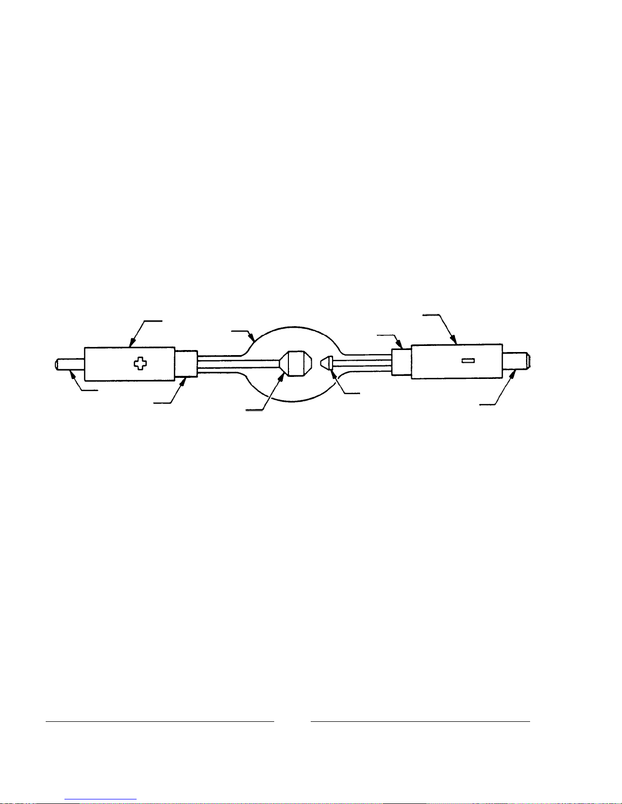
Anode Pin
Seal
Anode End Cap
Envelope
Anode
Cathode End Cap
Seal
Cathode
Cathode Pin
XG3/006

BULB INSTALLATION
OBSERVE ALL SAFETY PROCEDURES when working around the xenon bulb. Open the
lamphouse access door by releasing the key lock and removing the tamperproof screws using the special screw-
driver supplied. The igniter lead and contact clamp are tied off for shipping. Free the clamp and slide it over the
rear bulb support collet. Attach the cathode lead to the cathode end cap, if not factory-installed.
REMOVE THE PLASTIC PROTECTIVE COVER from the xenon bulb only if necessary.
Handle the bulb by the metal end caps only. Insert the bulb into the lamphouse, passing the anode (+) end cap
through the center hole of the reflector. Take care not to bump or scratch the surface of the reflector.
INSERT THE ANODE (+) PIN into the rear support collet and contact clamp. Rest the
cathode (-) end cap in the front bulb support yoke. Seat the anode (+) pin into the rear support collet as far as
possible for correct focus travel. Securely tighten the socket head clamping screw in the anode contact.
REST THE CATHODE END CAP in the V of the bulb yoke. Insulate the cathode bulb lead
using the length of silastic rubber tubing supplied. Dress the bulb lead directly in front of the bulb support yoke
to minimize the projected shadow. Attach the ring terminal on the end of the bulb lead to the negative binding
post inside the operators access door. Securely tighten the 3/8-16 hexnut.
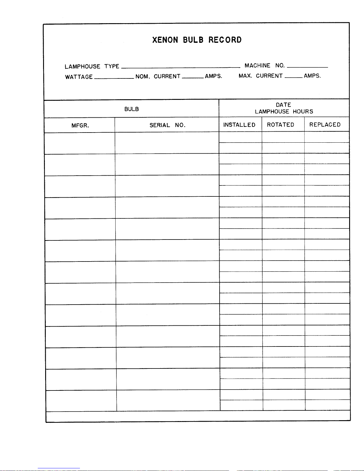
REMOVE THE PLASTIC COVER from the bulb. Record the bulb serial number, date, and
lamphouse hours on the Xenon Bulb Record on the inside back cover of this manual. This information will be
needed in the event of a bulb warranty adjustment.
XG3/007

ESTABLISH A ROUTINE of periodically checking all electrical connections for tightness.
Loose contacts, particularly in the DC circuit, will cause overheating and damage the xenon bulb and other
components. Normal xenon bulb warranties allow no credit for bulb damage caused by overheating.
REFER TO THE BULB MANUFACTURERS INSTRUCTIONS regarding bulb rotation.
Most bulb manufacturers recommend rotating the bulb 180° at 50% of warranty hours. After rotating the bulb,
operate at maximum allowable current for several hours, and then return to the nominal operating current.
IN THE EVENT of a bulb warranty claim, the bulb must be packaged in its original shipping
container, and returned with all required warranty forms completed. Contact the dealer through whom the bulb
was originally purchased for correct procedures and Return Authorizations.
IT IS A COMMON PRACTICE to replace the bulb at the expiration of its warranty period. If
a xenon bulb explodes in operation, the reflector and other lamphouse components are frequently damaged. The
xenon bulb manufacturer will extend no credit for a replacement reflector if the defective bulb is beyond war-
ranty. Explosion-damaged reflectors are to be returned to the bulb supplier, NOT Strong International, unless
the bulb was supplied by Strong.
XG3/008

OPERATION
INSTALL THE GLASS HEAT FILTER into the bracket mounted on the rear of the fadeout
and douser support housing. NOTE: The coated side of the filter, with the XX or other marking, must be
facing the reflector. Reach through the side door and nose opening of the lamphouse, slide the filter into the slot
in the top angle bracket, and lower it into the bottom slotted bracket.
REMOVE THE PLASTIC COVER from the xenon bulb. DO NOT ignite the lamp with the
cover on the bulb. Store the cover for future re-use.
CLOSE AND SECURE the lamphouse door using the tamperproof screws and special screw-
driver supplied with the lamphouse. Engage the cam lock and install the security screw. The door must be
completely secured to actuate the interlock switch and permit lamp ignition. Place the MODE switch in the
MAN. (manual) position.
TURN ON THE MAIN LINE SWITCH and/or circuit breaker to energize the xenon power
supply. The lamphouse blowers will start and the blower interlock switches will be actuated to permit lamp
ignition. The blowers will operate continuously until the xenon power supply is de-energized.
PLACE THE LAMP SWITCH in the ON position and the lamp will ignite. If ignition does
not occur, or the high voltage pulse is not apparent, press the emergency ignition switch on the top of the
lamphouse under the plug button. Do not hold more than one second; release immediately upon lamp ignition.
Use of the emergency ignition switch indicates an abnormal condition; see the TROUBLESHOOTING section
following.
CHECK THE READING on the lamphouse ammeter. Nominal current for the 3000 watt
xenon bulb is 95 amperes. DO NOT, AT ANY TIME, exceed 100 amperes. Output current is adjusted at the
power supply; see power supply manual for instructions. Operation of a new bulb is normally started at the
lower end of its range (85 A.), and current is gradually increased as the bulb ages to maintain light output.
PRESS THE SMALL PUSH BUTTON SWITCH located below the ammeter to read the DC
voltage at the arc. This permits immediate calculation of the power at which the lamp is operating (volts times
amperes = wattage). Holding this switch in during the ignition cycle will also briefly indicate the no load
(open circuit) DC voltage applied to the xenon bulb for ignition.
REMOVE THE REAR COVER PLATE below the instrument panel by withdrawing the two
plastic plungers. This exposes the bulb positioning controls in the lamphouse back casting.
TO FOCUS THE XENON BULB and obtain the best light on the stage, the two methods
outlined below are the most suitable.
MOVE THE SPOT SIZE CONTROL HANDLE (trombone) on the large lens carriage all the
way forward to project the smallest spot possible; place the iris, masking shutters (choppers) and the fadeout
douser blades in their full open positions. Project a spot to a wall or similar flat perpendicular surface opposite
the spotlight position.
XG3/009

THE CENTER SECTION of the bulb positioning controls is a threaded member that focuses
the bulb in relation to the reflector. Turning this adjustment moves the bulb in only one plane, into or away from
the reflector. Turning this section clockwise moves the bulb away from the reflector. The small knurled screw
to the left of this section can be tightened to lock the focusing mechanism after the following procedures have
been completed.
THE LARGE THUMB SCREWS, on either side of the focusing control, lock the horizontal
and vertical adjustment mechanism in position.
TURN THE CENTER FOCUSING SECTION of the bulb positioning control counterclock-
wise until a small black spot is projected onto the wall. It may be best to run this adjustment both directions to
permit positive identification of the spot.
LOOSEN THE TWO THUMB SCREWS, one on either side of the center focusing section,
just enough to permit manual movement of the complete assembly. The bulb positioning control will now move
around these two thumb screws, and as this control is shifted, the smooth shadow of the bulb electrode can be
seen extending beyond the projected center hole in the reflector. The shadow of the electrode (black spot) must
be centered in the projected hole of the reflector (shaded, less dense dark area).
MOVE THE CONTROL SECTION around the two screws until the black spot is as round as
possible to project. It may be necessary to again turn the focus control to project a sharply defined black spot.
AFTER THE BLACK SPOT is as even around the outside as possible to project, and appears
centered in the shaded reflector center hole, tighten the two large thumb screws to lock the position of the
mechanism. Turn the center focus control to obtain the brightest light with the best light distribution. Rotate the
lens spot focus control knob, located at the extreme front of the lens mechanism, to obtain the sharpest edge
possible on the projected spot.
THE SECOND METHOD of focusing the xenon bulb is to project the spot to the stage, and
working with the above lamphouse controls, adjust these controls to obtain a hot spot on the projected spot.
Then center this hot spot on the projected light by moving the entire control section around the two thumb
screws. Once this hot spot is centered in the projected light, lock the control in position with the two thumb
screws and turn the center section to obtain a spot with an even distribution of light. Rotate the lens spot focus
control knob to obtain a sharp edge on the projected spot.
XG3/010

THESE ADJUSTMENTS should not be disturbed until it is necessary to replace the xenon
bulb. At that time, the procedure on obtaining a smooth, round black spot, or hot spot, may have to be
repeated. Replace the cover plate over the bulb positioning controls.
BECAUSE OF NORMAL BULB AGING, and manufacturing tolerances between individual
xenon bulbs, it may be necessary to operate lamps at slightly higher or lower current settings to maintain
uniform light output when two or more spotlights are used in one installation. This entails a slight current
output adjustment at the xenon power supplies. See the power supply manual.
TO EXTINGUISH the arc, place the LAMP switch on the instrument panel to OFF. The
lamphouse blowers will continue to operate until the xenon power supply is de-energized. Allow the blowers to
operate for ten minutes before turning off the power supply; a forced-air bulb cooling cycle is required by all
bulb manufacturers.
DAILY OPERATION in the Manual mode requires only that the xenon power supply be
energized, the MODE switch be left in the MAN. position, and the lamp switched ON and OFF by means of
the LAMP switch. No bulb alignment or warm up are necessary. Always allow for the ten minute bulb
cooling cycle.
OPERATION IN THE AUTO MODE is intended for use only if the spotlight is to be used as
a fixed spot without an operator at the equipment. Place the MODE switch in the AUTO position, and the
LAMP switch to ON. The lamp will ignite when a sustained dry contact is made between the automation
leads 3 and 6, and extinguish when the contact is opened. See the INSTALLATION DIAGRAM in the power
supply manual. The lamphouse blowers will operate until the xenon power supply is de-energized; allow for ten
minutes bulb cooling.
BEFORE OPENING the lamphouse enclosure for servicing, allow the blowers to operate for
twenty minutes, or until the bulb has cooled to room temperature.
HANDLING THE SPOTLIGHT
GENERALLY THE BEST POSITION for the operator to stand is hear the center of the spot-
light on the right side. The angle of tilt, the size of the porthole, and the layout of the spotlight position may
dictate another location.
EACH OPERATOR will, after a few minutes of operation, generally develop his own system
and position for most convenient operation.
THE HORIZONTAL SWING and vertical tilt are individually adjustable to give the desired
degree of friction to suit the operator. The locking clamps are located on the right side of the yoke assembly.
THE EASE with which the spot size control handle (trombone) can be operated may be
adjusted by means of the nylon friction brake screw in the outrigger of the large lens carriage casting. To access
this adjustment, open the color boomerang and remove the gel frames. Slide the large lens carriage to the
extreme rear position. Reach through the boomerang housing and loosen the nylon friction screw locknut. Turn
the nylon friction screw clockwise to increase drag, or counterclockwise to relieve. Tighten the locknut after the
desired adjustment is eached.
XG3/011

OPERATION OF OPTICAL SYSTEM
THE IRIS CONTROL is the front lever which projects through the top of the optical system
housing. When this lever is to the left (as viewed from the rear of the unit), the largest aperture is provided.
Smaller apertures are obtained as the lever is moved to the right.
THE SPOT SIZE CONTROL HANDLE is located on the right hand side of the optical system
just above the base rail. A variation of spot sizes from full flood to small spot can be obtained by moving the
spot size control handle from one extreme to the other. Beam intensity is increased by this optical system when
reducing from flood to spot, and maximum intensity is reached when the spot size control handle is in the
extreme forward position.
THE MAXIMUM FLOOD SPOT is obtained with the iris control lever to the left (away from
operating side) for the largest aperture and with the spot size control handle moved as far to the rear as possible.
SMALLER SIZED SPOTS are projected as the spot size control handle is moved forward.
Most of the spot sizes needed will be produced with the iris in its maximum open position.
FOR A HEAD SPOT, or any spot smaller than can be obtained with the spot size control
handle in its extreme forward position, shift the iris control lever to the right (toward operating side) for a
smaller aperture. The iris control lever should always be returned to its extreme left position before the spot size
control handle is again moved to obtain larger spots.
THE MASKING SHUTTER (chopper) lever is the middle lever projecting through the top of
the optical system housing. The masking shutter blades are operated by this lever to shape the projected spot to
a rectangle, strip spot, or dousing.
THE DISENGAGED POSITION of the masking shutter lever is to the extreme right (toward
operating side) and varying degrees of masking to complete cutoff are obtained by moving the lever to the left
(away from operating side).
THE ANGLE of the masking shutter blades can be adjusted to compensate for the horizontal
projection angle. Remove the color boomerang and optical system housing, and loosen the screws holding each
of the masking shutter blades enough to allow adjustments. Ignite the bulb and adjust the angle of the bottom
blade by tapping with a screwdriver so its projected edge lies parallel to the footlights. Tighten the screw.
Operate the masking shutter lever to close the blades. Adjust the upper blade to close in line with the bottom
blade and tighten the screw.
THE FADEOUT MECHANISM AND DOUSER CONTROL is the rear lever projecting
through the top of the optical system cover. This lever controls the intensity of light from complete fadeout
when the lever is to the left, to full intensity when the lever is to the right.
THE SPOT FOCUSING CONTROL KNOB is located on the operating side of the optical
system at the forward end above the base rail. This control is used to adjust the optical system for the length of
throw. When making an adjustment, rotate the spot focusing control knob until the sharpest edge is obtained on
the projected spot.
XG3/012

OPERATION OF COLOR BOOMERANG
THE COLOR BOOMERANG is equipped with six color holders and an ultraviolet filter.
Additional filter holders can be supplied by an authorized Strong International Dealer.
TO OPERATE INDIVIDUAL COLOR FILTERS, lower the desired filter selector lever. A
rocker catch located in the color disc housing holds the filter in position.
TO RELEASE A COLOR, push the filter release button or engage another color, thus releas-
ing the previous color automatically.
TO REPLACE A FILTER HOLDER, open the hinged top of the color disc housing and lift out
the desired filter holder.
®
HIGH TEMPERATURE FILTERS (RoscoLux
or equivalent) cut to nine inch diameter are
required, and are secured in the filter holders with paper fasteners.
NOTE: WHEN PLACING COLOR FILTERS in the boomerang, the less dense colors (pink,
amber) should be placed in the holders toward the rear of the boomerang (toward arc), and those of greater
density (red, green) should be placed in the holders toward the front of the boomerang (away from the arc).
COLOR TEMPERATURE REDUCTION FILTERS, required for use with television and
videotape, are available from theatrical supply dealers.
XG3/013

MAINTENANCE
THE XENON GLADIATOR III SPOTLIGHT requires very little maintenance to keep it in
good working order.
THE REFLECTOR should be cleaned periodically with a soft, clean, lint-free cloth to remove
®
dust from the reflecting surface. If excessively soiled, the reflector may be cleaned with Windex
or an equiva-
lent glass cleaner. DO NOT use abrasive cleaners of any kind. Clean the heat filter glass; replace with the
coated surface toward the lamphouse.
CHECK ALL ELECTRICAL CONNECTIONS for tightness on a regular basis. Loose con-
nections, particularly in the DC circuit, may cause premature bulb failure and damage lamphouse components.
LUBRICATE the bulb seal blower and the lens blower with two or three drops of non-detergent
oil once every six months. The exhaust blower is permanently lubricated.
THE XENON BULB should be checked occasionally for the presence of dust or foreign mate-
rials. If necessary, clean the quartz envelope of the bulb with alcohol, and wipe dry with a clean, lint-free cloth.
Observe all safety procedures when working with the exposed bulb.
THE INSIDE OF THE LAMPHOUSE and the blower squirrelcages should be cleaned peri-
odically, depending on the dust conditions at each installation. Keep the blower inlet and outlet grilles clean to
permit free air flow. Clean the actuator arms of the air flow switches to prevent dust build-up.
THE LENS SYSTEM should be kept clean to prevent any light reduction in the projected spot.
Tighten the horizontal swing and vertical tilt locking clamps. Remove the color gels to reach and clean the back
surface of the large lens. Remove the cover casting over the fadeout, chopper, and iris controls to remove the
small projection lens which is held in place with a large spring-type retainer ring at the front of the lens barrel.
CLEAN THE PROJECTION LENS and large lens with with any cleaner approved for use on
coated projection lenses. Replace the projection lens with the end with the FL marking ring toward the iris;
secure with the retainer ring.
BEFORE TRANSPORTING the spotlight, remove the xenon bulb from the lamphouse. Place
the bulb in its plastic cover and original shipping container.
XG3/014

XG3/015

PARTS LIST
Lamphouse Schematic
Ref.
Desig. Part No. Description
B1 40905 Bulb Seal Blower Assembly, 220 V.AC, 50/60 Hz.
B2 71220 Exhaust Blower, 115 V.AC, 50/60 Hz.
B3 47944 Lens Cooling Blower, 115 V.AC, 50/60 Hz.
C1,2 76132 Capacitior, .005 µf, 600WVDC *
C3 76133 Capacitor, .01 µf, 400 WVDC *
C4A, 4B 76323 Capacitor, 1.0+1.0 µf, 600 WVDC
C5 81947 Capacitor, .01 µf, 500 WVDC
C6,7 40973 Capacitor, .05 µf, 600 V.DC
C8 39956 Capacitor, .05 µf, 1200 V.DC
DS1 78984 POWER Indicator Light, 115 V.AC
DS2 - Xenon Bulb, 3 kW
F1 21-21015 Fuse, 1.5 A.
M1 40971 Elapsed Time Meter, 60 Hz.
- 71281 Elapsed Time Meter, 50 Hz.
M2 40923 Ammeter, 0-150 A.
PCB 40913 Igniter Printed Circuit Board Assembly
R1 81247 Shunt, 200 A. 50 mV.
R2 71283 Resistor, 90.9k Ohm, ¼ Watt
S1 80168 Door Interlock Switch
S2 81275 LAMP Switch, Rocker Type
S3 81276 MODE Switch, Rocker Type
S4 39955 Air Flow Switch, Intake Blower
S5 40936 Air Flow Switch, Exhaust
S6 72275 VOLTAGE Switch, Pushbutton
- 39949A Igniter Assembly, Gladiator
- 40904 MS Connector & Interconnect Cable Assembly
- 88318 MS Connector, 14 Pin Male
* 40983 RF Suppressor Assembly (C1, C2, C3)
MS CONNECTOR
A - BLK DC Neg.
B - RED DC Pos.
C - BRN No . 2
D - RED No . 3
E - ORN No. 4
F - BLU No. 5
G - YEL No. 6
I - GRY No. 7
J - BLK No. 8
M - GRN Ground
XG3/016

PRINCIPLE OF IGNITER OPERATION
THE IGNITER is energized through the 115 V.AC control circuit when the LAMP ON-OFF
switch (S2) is depressed and all interlocks and air flow switches are closed.
CAUTION: Do not use the Emergency Ignition switch (S102) in the igniter until it is deter-
mined that the polarity of the xenon bulb is correct. Use of the S102 switch bypasses the polarity sensing diode
(CR201) on the igniter printed circuit board; if polarity is not correct, the bulb will be seriously damaged or
destroyed. No credit is allowed on bulbs damaged by reversed polarity.
THE IGNITER supplies a high RF voltage pulse to the bulb, together with the high No Load
DC voltage from the xenon power supply, to ignite the xenon bulb. After the arc is sustained, the AC circuit in
the igniter is interrupted by the opening of K201 relay contacts on the signal of the timer circuit on the PC board.
The DC output of the xenon power supply is automatically lowered to the power level required to maintain the
arc. The DC power to the bulb is dependent upon the bulb characteristics and the setting of the output of the
xenon power supply.
DC VOLTAGE is applied to the printed circuit board from the xenon power supply, energizing
the 12 V.DC coil and closing the contacts of K201 relay, completing the AC circuit through the igniter to the
T102 high voltage (10 kV.) transformer. High voltage boost capacitor C107 is charged to a voltage sufficient to
cause breakdown across the E101 spark gap. Approximately 35 kV. is supplied to the xenon bulb for ignition.
S101 is the igniter cover interlock switch and S102 is the Emergency Ignition switch, which is
a bypass for the K201 relay contacts and CR201 polarity sensing diode on the PC board. Components C101,
102, and 103 function as RF bypass capacitors on the igniter. The C108 capacitor serves as a coupling capaci-
tor to the current coil.
THE PC BOARD operates on DC voltage from the xenon power supply. Capacitor C201
across the positive #10 and negative #15 is an RF suppression capacitor. Resistor R201 and zener diodes
VR201 and 202 drop the DC voltage to 12 volts for the K201 relay coil. CR201 is the polarity sensing diode.
C204 is a polarized capacitor used for arc suppression at the K201 relay coil, and CR202 functions as a
transient protection diode.
THE FOLLOWING COMPONENTS are parts of the timing circuit on the PC board: Timer
chip U201, resistors R202, 203, and the polarized capacitor C203. The C203 capacitor functions as the timing
control, and CR203 serves as the ON time control diode. C202 is the control voltage isolation capacitor.
XG3/017

Ref.
Desig. Part No. Description
C107 39110 Capacitor, 2400 pf, 20 kV.DC
C108 39110 Capacitor, 2400 pf, 20 kV.DC
E101 39923 Spark Gap Assembly
S101 80168 Cover Interlock Switch
S102 80168 Emergency Ignite Switch
T101 39937 High Voltage Transformer
- 39998 Case & Coil, Potted Assembly
IGNITER ASSEMBLY, SCHEMATIC
XG3/018

Ref.
Desig. Part No. Description
C201 88263 Capacitor, .05 µf, 600 WVDC
C202 79127 Capacitor, .01 µf, 600 WVDC
C203 39156 Capacitor, 15 µf, 30/35 WVDC
C204 88249 Capacitor, .1 µf, 600 WVDC
CR201 85112 Diode, 2.5 A. 1000 PRV
CR202 85112 Diode, 2.5 A. 1000 PRV
CR203 85112 Diode, 2.5 A. 1000 PRV
K201 39154 Relay, P&B R10-E1-W2S800
- 39160 Relay Socket
- 39161 Relay Hold-Down Spring
R201 39157 Resistor, 1k Ohm, 12 Watt
R202 39158 Resistor, 100k Ohm, ½ Watt
Ref.
Desig. Part No. Description
R203 39159 Resistor, 200k Ohm, ½ Watt
U201 72185 Timer IC, Motorola MC11455P1
- 39164 IC Socket, (6) Pin
VR201 39211 Zener Diode, 1N5377A (40913*)
VR201 81519 Zener Diode, 1N5361 (40984*)
VR202 39162 Zener Diode, 1N4742
- 39145 PC Board (less Components)
* 40913 PCB Assembly, Standard
* 40984 PCB Assembly (Older Models using
High Reactance Power Supply)
Assembly Number written on Component Side of PCB.
IGNITER PRINTED CIRCUIT BOARD
ASSEMBLY, SCHEMATIC
XG3/019
WIRE MARKERS
A = 10
B = 15
C = 17
D = 38

TROUBLE CHART
NORMAL OPERATION
WHEN THE SWITCH in the main AC supply line to the xenon power supply is in the ON
position, and the 30 A. circuit breaker on the switching power supply is ON, the POWER lights on the xenon
power supply and the lamphouse instrument panel will glow. The lamphouse blowers will start. The blowers
in the power supply will operate.
OPERATION OF THE LAMPHOUSE BLOWERS will close the (2) air flow interlock switches,
and if the lamphouse door is closed and correctly secured, the control circuit to the LAMP switch will be
completed.
THE MODE SWITCH, located on the lamphouse instrument panel, should be in the MAN.
(Manual) position.
WHEN THE LAMP SWITCH is placed in the ON position, the AC control circuit (5 & 6) in
the lamphouse will energize the power supply circuitry providing DC current to the igniter and bulb.
THERE WILL BE a distinctly audible high voltage arc ping at the igniter arc gap and across
the bulb electrodes. The bulb should ignite immediately after one or two of these high voltage pulses, and the
lamp current will adjust to the output setting of the xenon power supply. Multiple ignition pulses prior to bulb
ignition normally indicate a low DC output setting. See xenon power supply manual. A warm or aged xenon
bulb might also require multiple strikes.
TROUBLE SHOOTING
IF THE XENON BULB does not ignite, observe the following operational sequences for assis-
tance in locating and isolating the trouble area.
WHEN THE FAN(S) and the indicator light on the power supply are on, the circuit in the
power supply is trouble-free up to the terminal block in the power supply.
AT THIS TIME, the lamphouse blowers should operate. If this does not occur, the trouble is
in the door interlock switch, one of the blower motors, a loose connection, a broken #2, #4, #7 or #8 lead, or a
blown F1 seal blower fuse. Check the 1.5 A. fuse in the in-line fuseholder.
CAUTION: In order to prevent bulb
ignition when checking the AC control circuit in the lamphouse, remove lead #10 from the igniter terminal strip.
CHECK AT THIS TIME for 115 V.AC Control Voltage at the access door interlock switch
(wires 2 & 4), and 220 V.AC at the blower terminals (7 & 8). The door interlock switch must be manually
actuated to energize the exhuast and lens blowers. Replace #10 lead before proceeding.
THE VANES on the air flow switches should raise. With the MODE switch in the MAN.
position and the LAMP switch in the ON position, the running time meter should start and indicate elapsed
time. If this meter does not operate, check for continuity at the MODE and LAMP switches.
A DEFECTIVE RUNNING TIME METER will not prevent bulb ignition.
XG3/020

WITH THE LAMP SWITCH in the ON position, a distinct high voltage arc ping should
be heard at the spark gap in the igniter, and the flash of the xenon bulb should be visible through the ammeter as
a high DC voltage pulse is applied across the bulb electrodes.
IF THE HIGH VOLTAGE PING or the flash at the ammeter is not apparent, check for 115
V.AC at terminals 5 & 6 at the terminal board. If 115 V.AC is present, and terminals are tight, check then the
No Load DC Voltage between the lamphouse and power supply. Remove either lead #5 or #6 at the terminal
board to prevent bulb ignition and defeat the door interlock switch. Check the DC voltage across terminals #10
(+) and #15 (-). A reading of 85 V.DC should be measured if using a high reactance power supply; 120-170
V.DC if using a switching type. If this voltage is not indicated, the problem is in the leads between the lamp-
house and power supply, or in the power supply boost circuit. See the trouble shooting section of the power
supply manual for additional instructions. Replace lead #5 or #6 at the igniter before proceeding.
THE SWITCHING-TYPE XENON POWER SUPPLY furnished with the spotlight system
includes thermal overload switches and protection circuits to prevent damage resulting from high or low input
voltage. Loss of DC open circuit voltage, or an interruption of DC sustaining current, may be traced to these
circuits. See the power supply manual.
IGNITER PRINTED CIRCUIT BOARD 40913 is required for use with the switching type
xenon power supply. If the lamphouse is equipped with an older type (40984), replace it with the 40913 board.
If the lamphouse ignites only by means of the emergency ignition switch, replace the igniter PC board.
IF THE HIGH VOLTAGE ARC is audible at the lamphouse and the bulb does not flash, check
for a lamphouse DC lead arcing to ground. If no ground fault is detected, replace the bulb and attempt ignition
with the new bulb.
IF THE HIGH VOLTAGE ARC is audible at the lamphouse, the flash of the bulb is visible in
the ammeter, but ignition of the bulb is not sustained, the problem area is in the power supply. See the trouble
shooting section of the power supply manual for additional instructions.
IF THE HIGH VOLTAGE ARC is not audible or the flash of the bulb visible, the problem is in
the igniter or igniter PC board assembly.
EXCHANGE of components (i.e. igniters, printed circuit boards) between similar Strong
Xenon Gladiators to aid in diagnosis of a problem is encouraged. This will not lead to equipment damage, and
will not void equipment warranty.
XG3/021

XENON GLADIATOR III TROUBLESHOOTING
Bulb fails to ignite.
1. MODE switch S3 set to AUTO. Place in MAN. position when not employing automated or remote
lamphouse operation.
2. AC power not on to lamphouse. Turn switching power supply 30 A. circuit breaker ON. If 115 V.AC
not read at 2 & 4, or POWER indicator not glowing, see power supply manual.
3. Door interlock switch (S1) open. Close and secure lamphouse door.
4. Faulty interlock switch(s). Check for 115 V.AC at 9 & 12; replace switch(s) if defective.
5. Air vane switches not closing. Check for unobstructed operation; clean if required. Check continuity
between NO and COM; replace if defective.
6. Faulty S2 ON-OFF switch. Check for voltage at 3 & 5; check for loose terminals or wiring. Replace
if defective.
7. Blower fuse F1 blown. Replace as required (1.5 A. Std.).
8. Low AC source voltage actuating brownout protection circuit in xenon power supply.
Bulb fails to ignite; ping audible, bulb flash visible.
1. Inadequate DC output from xenon power supply. Set power supply output to correct range required for
bulb wattage (95 A. nominal for 3000 watt).
2. If bulb flash is visible but faint, check for defective HV capacitor(s) in igniter. Replace if defective.
3. Faulty or expired xenon bulb. Replace as required.
Bulb fails to ignite; ping audible, no bulb flash.
1. Faulty xenon bulb. Check for cracked electrodes or darkened envelope. Replace if defective.
2. Ignition pulse shorting to ground. Inspect DC leads for burned insulation; dress leads away from
grounded metal components.
No high voltage ping audible; MODE switch in MAN. and LAMP switch in ON.
1. Loss of AC control voltage. Check xenon power supply for tripped circuit breaker or open thermal
switch. See power supply manual.
2. Little or no DC No Load voltage. Measure DC No Load voltage at 10 & 15. See power supply
manual.
3. Open fuse F1 (600 V.) on switching power supply. SEE POWER SUPPLY MANUAL. Allow (20)
minutes for capacitor discharge before replacing.
4. Faulty igniter printed circuit board. If lamphouse ignites immediately when emergency ignition switch
is pressed, replace printed circuit board.
5. Loose spark gap connections or terminals. Repair or replace as required.
7. Faulty igniter. Check for 115 V.AC at 5 & 6; adequate DC No Load at 10 & 15. If present, and
igniter does not fire, replace igniter.
XG3/022

Bulb goes out during operation.
1. Xenon power supply overheated; thermal switch open. Check power supply blower(s), air inlets and
outlets unobstructed. See power supply manual.
2. Xenon bulb depressurizing. Check for envelope discoloration; replace if defective.
3. Lamphouse blower not moving adequate air. Clean; lubricate seal blower.
4. Lamphouse blower failed or obstructed. Clean dust and dirt from blower inlet grille. Check for 220
V.AC at 7 & 8; replace blower if defective.
5. Lamphouse air vane switches faulty. Check for vane actuation; adjust or replace as required.
6. Lamphouse exhaust obstructed. Clear obstruction; clean outlet grille.
7. Exhaust air flow switch reacting to backdraft. Adjust actuator to compensate for backdraft.
8. Fluctuating AC source voltage actuating brownout or spike protection circuits in xenon power supply.
See power supply manual.
Power supply does not energize when actuated.
1. Door interlock switch, B1 blower, F1 blower fuse, S4 air vane switch, S2 power switch, S3 MODE
switch. Check for 115 V.AC at each station; replace defective component.
SEE POWER SUPPLY TROUBLESHOOTING UNDER SAME HEADING.
Noise in theatre sound as bulb ignites.
1. Faulty RF suppression capacitor(s). Remove and test C1, C2, C3, C4A or C4B. Replace if defective.
2. Lamphouse, power supply, or sound system not properly grounded. Connect to adequate earth ground.
3. Leads between lamphouse and automation contact not shielded. Shield leads in conduit. (AUTO
Mode applications only.)
Excessive light flicker..
1. Faulty or aged bulb. Check for cracked or sagging electrodes; replace if defective.
2. Excessive ripple in DC output. See power supply manual.
3. Arc stabilization magnet reversed. NORTH pole should point toward opertors side. Check with
compass if required.
Reduced light output.
1. Normal bulb aging. Increase output current. DO NOT EXCEED MAXIMUM CURRENT LEVEL
SPECIFIED BY BULB MANUFACTURER.
2. Soiled reflector. Clean using commercial glass cleaner; USE NO ABRASIVES.
3. Soiled heat filter, projection lens, or large lens. Clean as required.
Extremely long duration between ignition pulses.
1. Low DC no load voltage from the xenon power supply. Check no load voltage; see power supply
manual.
2. Defective spark gap. A Ping sound is normal; excessive Hissing is abnormal. Replace if defective.
XG3/023

Extremely long duration between ignition pulses (continued)
3. Low AC voltage to lamphouse. Check for 115 V.AC at 2 & 4; if below 95 volts, check stepdown
transformer in xenon power supply. See power supply manual.
4. Defective timer IC chip on igniter PC board. Replace if defective.
Igniter continues to fire after bulb ignites.
1. Faulty igniter printed circuit board. Replace circuit board IMMEDIATELY to prevent bulb damage.
Color gels burning or fading prematurely.
1. Bulb focused to hot spot. Refocus bulb to flat field with iris fully open and spot size control handle
(trombone) fully forward.
2. Heat filter glass reversed or peeled. Check for coated surface toward bulb; replace if coating peeled.
3. Reflector coating peeled. Replace if defective.
XG3/024
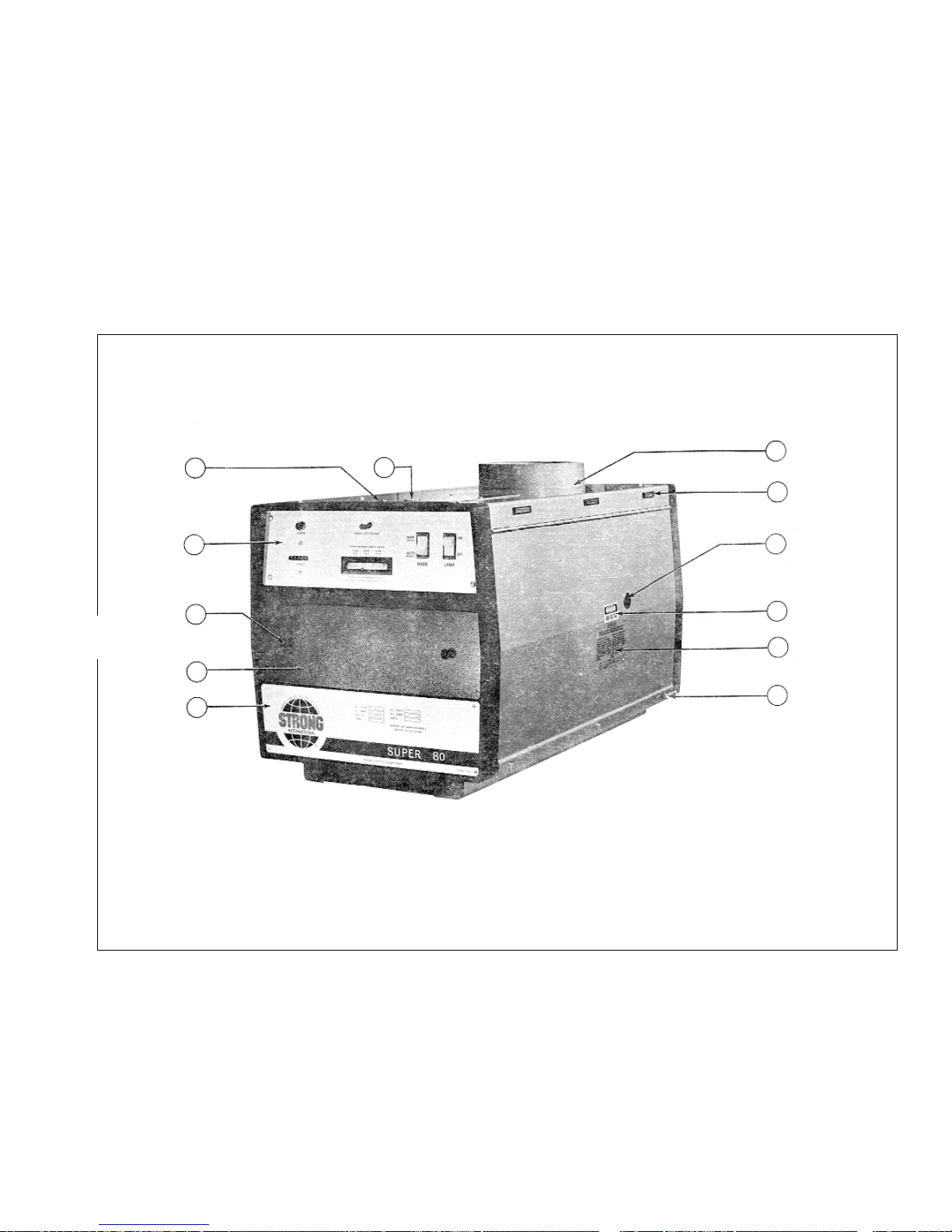
FIGURE 1
XG3/025
1
2
3
4
5
6
7
8
9
10
11 12

PARTS LIST
Figure 1
Item Part No. Description
1 40955 Top Cover & Door Welded Assembly
- - See 40951 Drawing for Exhaust Assembly
- 01307 Screw, 10-32 x 2/3" Pan Head
- 00885 Lockwasher, #10
2 39139 Magnetic Door Catch (early models*.)
3 48930 Arc Viewing Port
4 65353 DANGER Label
5 81282 CAUTION Label
- 01639-5 Pop Rivet, 1/8"
6 01736-1 Tamperproof Screw, 10-32 x 1/2" Holt Head
- 01715 Flatwasher, #10
- 01507 Tinnerman Nut, #10 (Clip-On)
- 65149A Screwdriver (for 01736-1)
7 40100 Name & Data Plate, Super 80
- 01639-2 Pop Rivet, 1/8"
8 40992 Cover Assembly, Bulb Adjust Controls
- 40119 Cover Plate
9 65166 Plunger, Black Plastic
- 65167 Grommet, Black Plastic
10 40986 Instument Panel Assembly (see Figure 2)
11 39982 Igniter Access Panel
- 01304 Screw, 8-32 x 5/16" Pan Head
- 00891A Lockwasher, #8
12 57275 Plug Button, Emergency Ignite Switch
* See Figure 3, Item 1 for Door Catch (current production)
XG3/026
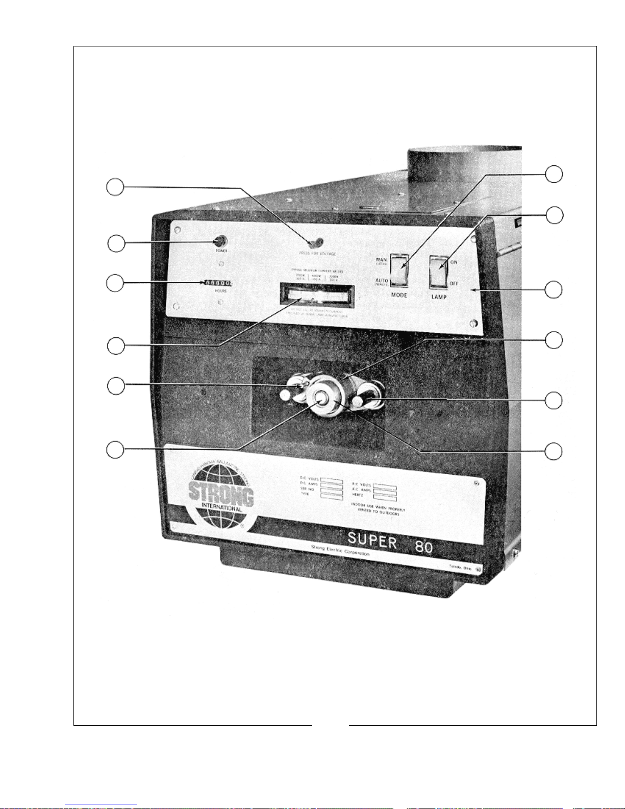
12
11
1
2
10
7
3
9
4
8
5
6
FIGURE 2
XG3/027

PARTS LIST
Figure 2
Item Part No. Description
1 81276 MODE Switch (S3)
2 81275 LAMP Switch (S2)
3 40102 Plate, Instrument Panel
- 01423 Screw, 10-32 x 5/16" Pan Head
4 65116 Casting, Bulb Adjust Mechanism
5 37985 Thumbscrew
- 15010 Compression Spring
- 65150 Fender Washer
6 65959 Focus Screw & Bearing Assembly
7 40953 Bulb Support Collet (see Figure 3, Item 14)
- 21-48027 Snap Ring, Collet Retaining
8 65153 Thumbscrew, Focus Lock
- 65154 Nylon Locking Ball
9 40923 Ammeter (M2)
- 71532 Mounting Plate, Ammeter
10 40971 Elapsed Time Meter (M1), 60 Hz.
- 40963 Elapsed Time Meter, 50 Hz. (Export)
11 78984 POWER Indicator Light (DS1), 115 V.AC
12 72275 Switch (S5), Voltage Test
- 71283 Resistor (R2)
- 72276 Button, Plastic
XG3/028
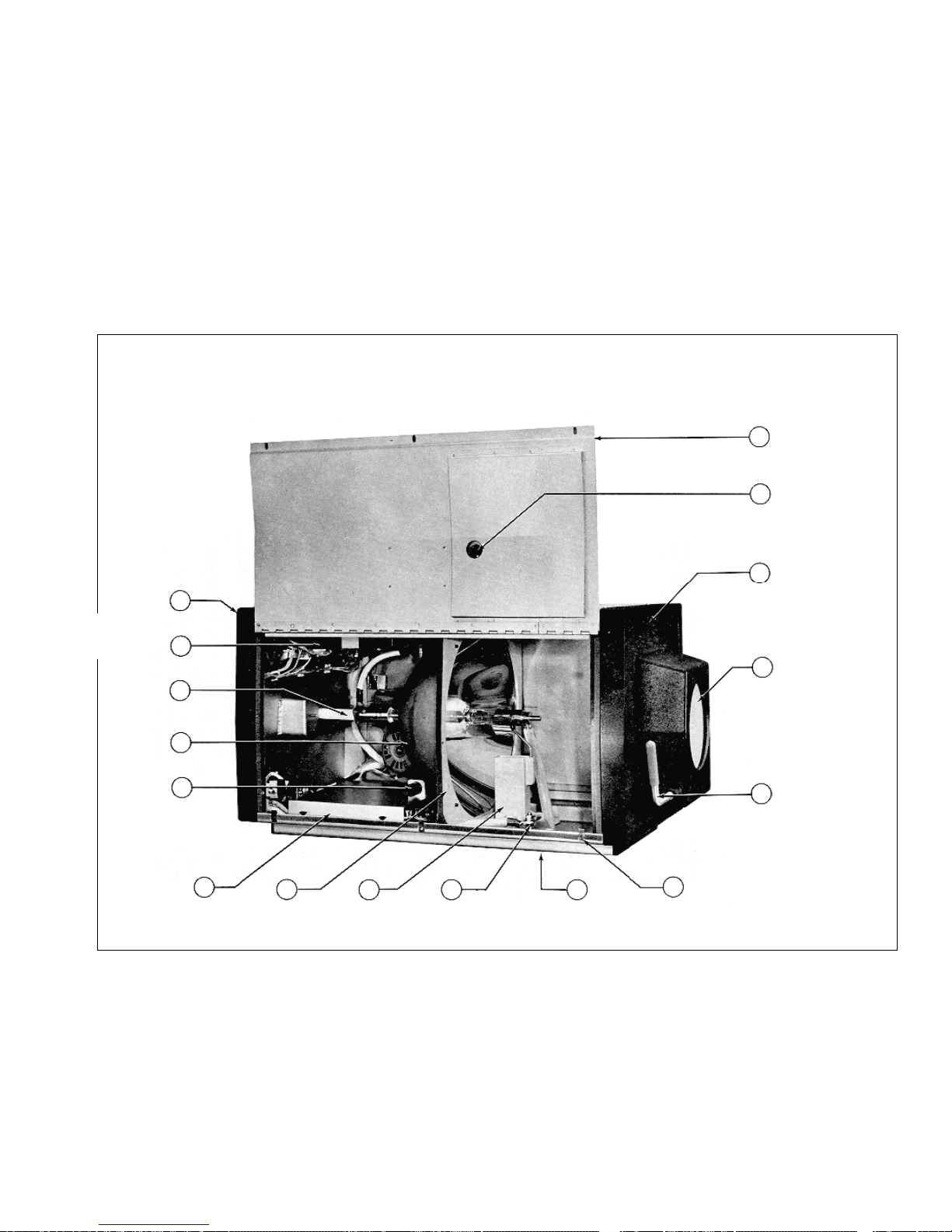
FIGURE 3
1
2
3
4
5
6
78910
11
12
13
14
15
16
XG3/029

PARTS LIST
Figure 3
Item Part No. Description
1 40955 Door & Top Cover Welded Assembly
- 01345 Screw, 10-32 x 1/2" Pan Head
- 00885 Lockwasher, #10
- 40174 Upper Bracket, Door Catch
- 40175 Door Catch Plate, Slotted
- 40176 Lower Bracket, Door Catch
- 40173 Stud, Door Catch Plate
2 48930 Arc Viewing Port
3 40958 Front Casting, Gladiator III
- 40958 does not include snood & douser (as illustrated)
4 - Douser Assembly not used
5 - on Gladiator Lamphouse
6 01507 Tinnerman (Clip-On) Nut, #10
7 40985 Lamphouse Base Pan
8 40987 Binding Post Assembly (E1)
- 40130 Phenolic Block
- 00642 Contact Screw, 3/8-16 x 1-1/2" Flat Head
- 40131 Fibre Insulator
- 00809 Jam Nut, 3/8-16 Hex
- 00854 Flatwasher, 3/8"
- 00492 Mounting Screw, 1/4-20 x 3/4" Flat Head
- 00805 Hexnut, 1/4-20
9 40107 Air Duct Casting
- 01796 Mounting Screw, 5/16-18 x 3/4" Hex Head, Nylon
- 40116 Fibre Insulator
- 40900 Bulb Support Yoke
- 00781 Yoke Set Screw, 8-32 x 1/4"
10 40104 Reflector Bulkhead Casting
- 40142 Tie Rod, 1/4-20
- 00805 Lock Nut, 1/4-20 Hex
11 40120 Dust Cover
- 01742 Screw, 8-32 x 1/4" Pan Head
- 00891A Lockwasher, #8
12 M15315 Arc Stabilizer Magnet
- 81137 Magnet Clamp
- 00781 Set Screw, 8-32 x 1/4"
- 01710 Clamp Mounting Screw, 8-32 x 1/4" Hex Head
XG3/030

PARTS LIST, Figure 3 (continued)
Item Part No. Description
13 23754 Flanged Reflector, 15" Dichroic
- 01432 Mounting Screw, 1/4-20 x 1/2" Socket Head
- 00852 Flatwasher, 1/4"
14 40953 Rear Bulb Support Collet
- 21-48027 Retaining Ring
- 40944 Igniter Lead & Clamp Assembly
- 40114 Clamp
- 01532 Clamping Screw, 8-32 x 7/8" Socket Head
- 00685 Lead Mounting Screw, 1/4-20 x 3/8" Hex Head
15 39949A Igniter Assembly (see Figure 5)
16 40105 Rear Casting
NOT SHOWN
71284 Cam Lock & Key, Lamphouse Access Door
XG3/031

19
18
17
16
1
2
15
14
13
12
FIGURE 4
XG3/032
3
4
5
6
891011
7

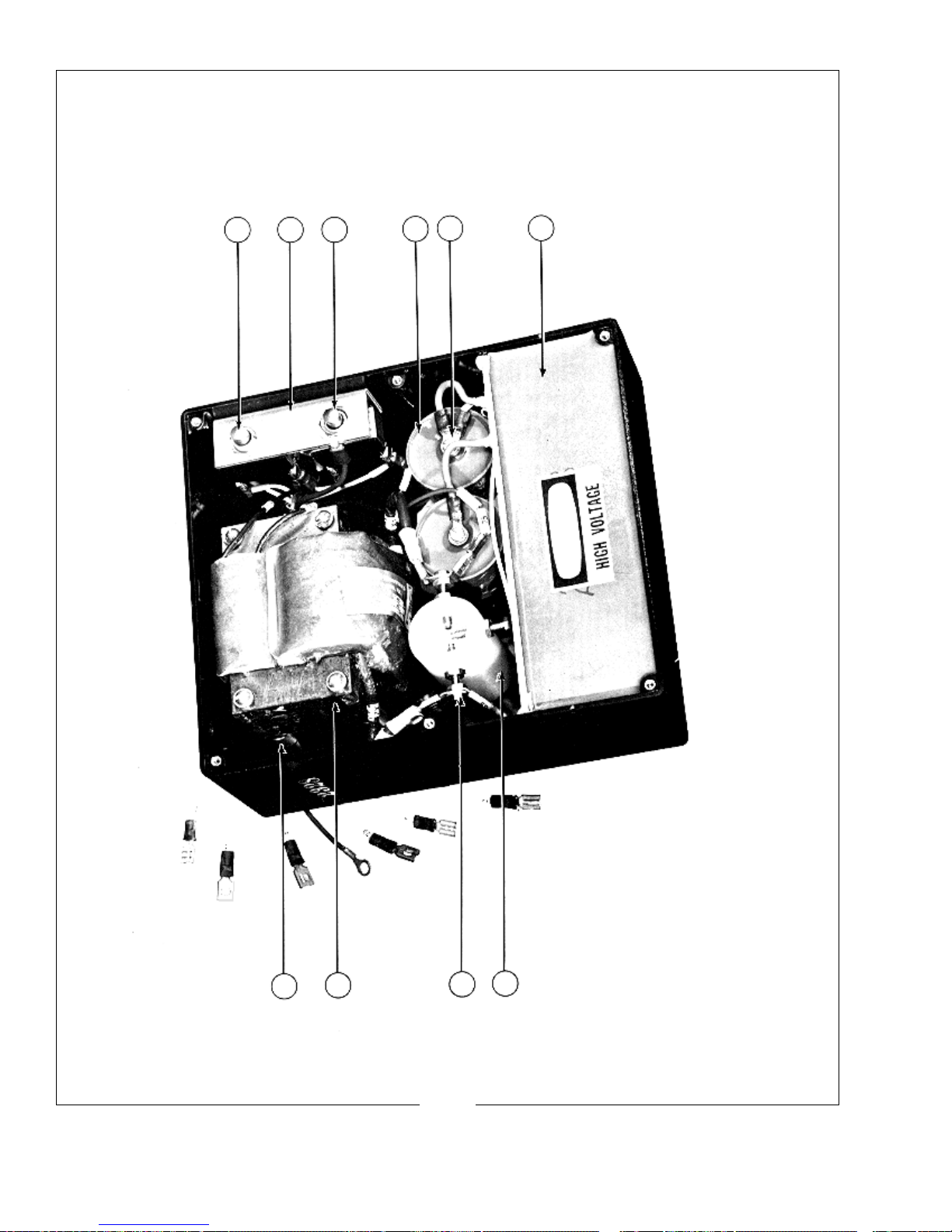
PARTS LIST
Figure 4
Item Part No. Description
1 40905 Bulb Seal Blower Assembly (B1), 220 V.AC, 50/60 Hz.
- 40993 Blower Inlet Grille
- 01311 Screw, 8-32 x 3/8" Pan Head
- 00891A Lockwasher, #8
2 40136 Capacitor Clamp
- 01382 Clamp Mounting Screw, 8-32 x 3/16" Pan Head
- 00891A Lockwasher, #8
3 76323 Capacitor (C4A & C4B)
4 40981 Cable Assembly, Shunt to Binding Post
5 40983 RF Suppression Capacitor Assembly (C1,2,3)
- 39153 PCB Stand-Off, Nylon
6 76133 Capacitor (C3)
7 76132 Capacitor (C1, C2)
8 40913 Igniter Printed Circuit Board Assembly
- 40984 Igniter PC Board (with High Reactance power supply)
- 39154 Relay, PC Board (K201)
- 39153 PCB Stand-Off, Nylon
9 40974 Capacitor (C8)
10 40103 Barrier Strip, (14) Terminal
- 40138 Insulated Marker Strip
- 01799 Screw, 8-32 x 9-16" Round Head
- 00891A Lockwasher, #8
11 80168 Door Interlock Switch (S1)
- 72178 Switch Bracket, Recessed
- 00167 Screw, 6-32 x 1/2" Flat Head
- 41-35005 Hexnut, 6-32
12 81247 Shunt (R1), 200 A. 50 mV.
- 01312 Screw, 8-32 x 1/2" Pan Head
- 00891A Lockwasher, #8
13 40973 RF Bypass Capacitor Assembly (C6, C7)
14 40961 Fuse Wire Assembly
- 39199 Fuse Holder
- 21-21015 Fuse (F1), 1.5 A
15 81274 Ground Lug
16 40904 Lamphouse/Power Supply Interconnect Cable Assembly
- 81143 Cable Connector, 90° Elbow
17 40953 Rear Bulb Support Collet
- 40944 Igniter Lead & Clamp Assembly
18 39955 Air Flow Switch (S4)
- 00953 Screw, 4-40 x 1/2" Round Head
19 40164 Light Baffle & Wiring Channel
- 01566 Screw, 10-24 x 5/16" Pan Head
XG3/033
IGNITER ASSEMBLY
2
1
3
4
5
6
10
9
7
8
FIGURE 5
XG3/034

PARTS LIST
Figure 5
Item Part No. Description
1 80168 Cover Interlock Switch (S101)
2 39113 Switch Bracket
- 00343 Screw, 10-32 x 1/2" Flat Head
3 80168 Emergency Ignite Switch (S102)
4 39110 High Voltage Capacitor (C107, 108)
- 00254 Screw, 8-32 x 1/4" Fillister Head
- 00891A Lockwasher, #8
- 39112 Capacitor Mounting Plate
- 01752 Screw, 1/4-21 x 1" Hex Head Nylon
- 01754 Hex Nut, 1/4-20 Nylon
5 01742 Screw, 8-32 x 1/4" Pan Head
- 00891A Lockwasher, #8
6 39998 Case & Current Coil, Potted Assembly
- 65353 DANGER Label
7 39201 * Spark Gap Body, Nylon
- 01567 Screw, 10-24 x 1/2" Pan Head
8 39107 * Contact Screw, Tungsten
- 39109 Terminal Tab
- 00831 Flatwasher, #10 Brass
- 00795 Hexnut, 8-32
* 39923 Spark Gap Assembly (Items 7 & 8, Gapped)
9 39937 High Voltage Transformer (T102)
- 01582 Flatwasher, #8
- 00795 Hexnut, 8-32
10 39204 Transformer Spacer
NOT SHOWN
39101 Igniter Box Cover, Black Plastic
01305 Cover Mounting Screw, 6-32 x 1/4" Pan Head
XG3/035

LAMPHOUSE EXHAUST BLOWER
Assembly No. 40951
72375
40937
71220
39173
78133
81545
Switch Location,
earlier models
Part No. Description
39173 Switch Bracket
40937 Blower Housing, Welded Assembly
71220 Blower (B2), 115 V.AC, 50/60 Hz.
40949 Plug & Cord Assembly
72375 Barrier Strip, (2) Terminal
78133 Air Flow Switch (S5)
81545 Actuator, Air Flow Switch
40936 S5 Switch Assembly (78133 & 81545)
XG3/036

FIGURE 6
XG3/037

PARTS LIST
Figure 6
Item Part No. Description
1 49943 Lifting Strap
2 00854 Flatwasher, 3/8"
3 49120 Tilt Axis Bolt
4 01319 Locknut, 3/8-16 Hex
5 02411 Washer, .640" I.D. x 1-1/4" O.D.
6 49126 Clamp Plate
7 49125 Compression Spring, Tilt Clamp
8 49124 Spring Bushing
9 49223 Clamp Shaft
10 49130 Clamp Handle
11 10048A Knob, Round Plastic
12 49290 Swivel Clamp Shaft
- 49291 Stop Plate, Horizontal Swivel
- 01523 Bolt, 3/8-16 x 2-1/2" Square Head
13 49130 Clamp Handle
14 83799 Base Column, Welded Assembly
15 83297 Mounting Bolt, Base Leg
- 00878 Lockwasher, 3/8" Split Ring
16 83797 Base Leg, Welded Assembly
- 47238 Tandem Caster, Locking (not shown)
17 49226 Leveling Foot
- 00992 Locknut, 1/2-13 Hex
18 83294A Height Adjustment Pin
19 83794 Tube & Collar Assembly
20 83113 Needle Bearing
21 83114 Race, Needle Bearing
22 49213 Swivel Clamp Collar
- 00687 Screw, 1/4-20 x 1/2" Hex Head
- 00876 Lockwasher, 1/4" Split Ring
23 83357 Yoke Cover Plate
- 01311 Screw, 8-32 x 3/8" Pan Head
- 00891A Lockwasher, #8
24 83112 Collar, Inner Tube
- 01759 Set Screw, 1/4-28 x 3/8" Dog Point
25 47951 Yoke Assembly
26 41-51147 Screw, 3/8-16 x 1"
- 00878 Lockwasher, 3/8"
- 41-70007 Flatwasher, 3/8"
- 41-35020 Hexnut, 3/8-16
27 47958 Saddle & Quadrant Assembly
28 83341 Cable Clamp
- 41-51121 Screw, 1/4-20 x 5/8" Hex Head
XG3/038

FIGURE 7
XG3/039

PARTS LIST
Figure 7
Item Part No. Description
1 49342 Hand Rail
- 00877 Lockwasher, 5/16" Split Ring
- 01346 Screw, 5/16-18 x 1/2" Hex Head
2 47944 Blower Assembly (B3), with Item 5
- 44191 Blower Motor & Squirrelcage, 115 V.AC
- 21-40011 Plug, (2) Pin Male
- 31-62007 Molex Pin, Male
- 21-40019 Receptacle, (2) Pin Female
- 31-62006 Molex Pin, Female
3 01311 Screw, 8-32 x 3/8" Pan Head (as reqd.)
4 47177 Receptacle Bracket (not reqd. in current units)
5 21-71066 Cable, 18/2 Type SJ (incl. with Item 2)
6 47945 Base Rail, Welded Assembly
NOT SHOWN
47989 Front Counterweight
47988 Counterweight Bracket
01346 Screw, 5/16-18 x 1/2" Hex Head
00877 Lockwasher, 5/16" Split Ring
00837 Flatwasher, 5/16"
00687 Screw, 1/4-20 x 1/2" Hex Head
00876 Lockwasher, 1/4" Split Ring
00835 Flatwasher, 1/4"
XG3/040
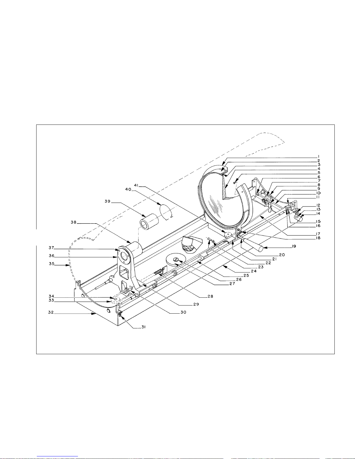
FIGURE 8
XG3/041

PARTS LIST
Figure 8
Item Part No. Description
1 51417 Large Lens Retainer
2 51914 Lens Ring, Welded Assembly
3 51418 Rubber Gasket, Lens Mount
4 51408 Large Lens, 11" Diameter
5 00253 Screw, 8-32 x 3/16" Fillister Head
6 00919 Cotter Pin, 1/16" x 1/2"
- 00831 Flatwasher, #10 Brass
7 51133 Adjusting Block, Lens Focus
- 00179 Screw, 6-32 x 1/4" Fillister Head
- 00892 Lockwasher, #6
8 51352 End Casting, Front
9 47207 Stud, Lens Focus Adjust
- 00541 Screw, 1/4-20 x 1/2" Pan Head
- 00889 Lockwasher, 1/4"
10 51454 Adjusting Screw, Lens Focus
11 48127 Retaining Ring
12 00541 Screw, 1/4-20 x 1/2" Pan Head
- 00889 Lockwasher, 1/4"
13 41-51170 Set Screw, Focus Adjust Knob
14 51168 Focus Adjust Knob
15 51114 Stop Collar, Slide Rod
- 00720 Set Screw, 10-32 x 3/16"
16 51479 Rubber Bumper
17 51910 Ribbon Assembly, Lens Focus
18 00381 Screw, 10-24 x 3/8" Fillister Head
- 00894 Lockwasher, #10 Split Ring
19 51509 Handle, Red Plastic
20 51441 Handle Shaft
- 51428 Retaining Ring
21 51350 Support Casting, Large Lens Carriage
22 01754 Locknut, 1/4-20 Hex Nylon
23 01752 Friction Brake Screw, 1/4-20 x 1" Hex Head Nylon
24 47968 Base Pan, Welded Assembly
25 51453 Slide Rod (Left & Right)
26 51160 Pulley Stud
- 00830 Flatwasher, #8 Brass
27 47210 Large Pulley
XG3/042

PARTS LIST, Figure 8 (continued)
Item Part No. Description
28 51162 Expansion Spring, Ribbon Tension
29 51354 Support Bracket, Slide Rods
- 00541 Screw, 1/4-20 x 1/2" Pan Head
- 00889 Lockwasher, 1/4"
30 51120 Retaining Clip, Spring & Ribbon
- 01304 Screw, 8-32 x 5/16" Pan Head
- 00891A Lockwasher, #8
- 00919 Cotter Pin, 1/16" x 1/2"
31 00541 Screw, 1/4-20 x 1/2" Pan Head
- 00889 Lockwasher, 1/4"
32 51353 End Casting, Rear
33 83163 Small Pulley
34 51160 Pulley Stud
- 00830 Flatwasher, #8 Brass
35 47967 Lens Mechanism Housing, Welded Assembly
- 23059A STRONG Insignia
- 47168 GLADIATOR Insignia
- 45256 Insignia, Roman Numeral III
- 47962 Rubber Light Baffle, for Item 20 Shaft
- 47948* Housing Extension & Heat Shield Welded Assembly
36 83160 Support Casting, Projection Lens
37 00237 Screw, 8-32 x 3/8" Flat Head
38 83144 Mounting Tube, Projection Lens
39 44239 Projection Lens, Compound
40 83155 Retaining Ring, Projection Lens
41 47211 Pulley, Large Lens Carriage
* Not Shown
XG3/043

58
59
FIGURE 9
Item 58 Bracket mounts to
back surface of Item 31.
XG3/044

PARTS LIST
Figure 9
Item Part No. Description
1 10048A Knob, Red Plastic
2 51451 Iris Shaft
3 00180 Screw, 6-32 x 5/16" Fillister Head
4 00892 Lockwasher, #6
5 51978 Friction Spring & Button
- 51229 Friction Pad
6 00184 Screw, 6-32 x 5/8" Fillister Head
7 00862 Lockwasher, #6
8 51979 Iris (as shown; see Fig. 9A for current configuration)
- 83181 Plate, 51979 Iris
- 83182 Retaining Clip, 51979 Iris
9 51226 Pivot Stud
10 83773 Aperture Support Plate
11 51160 Pulley Stud
12 83163 Large Pulley
13 00830 Flatwasher, #8 Brass
14 47191 Masking Blade
15 47982 Slide Assembly, Masking Blade
16 00886A Lockwasher, #8 Split Ring
17 00253A Screw, 8-32 x 3/16" Fillister Head
18 00853 Flatwasher, 1/4"
19 51156 Friction Plate
20 83134 Fadeout Pull Rod, Long
21 00876 Lockwasher, 1/4" Split Ring
22 00805 Hexnut, 1/4-20
23 00831 Flatwasher, #10 Brass
24 01344 Lockwasher, #10
25 00378 Screw, 10-32 x 1/4" Fillister Head
26 00378 Screw, 10-32 x 1/4" Fillister Head
27 01344 Lockwasher, #10
28 00831 Flatwasher, #10 Brass
29 83351 Retaining Strip, Fadeout Bracket
30 51226 Pivot Stud
31 83890 Fadeout Support Assembly
32 83892 Fadeout Blade, Lower
33 83891 Fadeout Blade, Upper
34 51153 Spacer Bushing
XG3/045

PARTS LIST, Figure 9 (continued)
Item Part No. Description
35 83133 Fadeout Pull Rod, Short
36 01704 Spring Pin
37 51357 Cover Plate Casting
38 00541 Screw, 1/4-20 x 1/2" Pan Head
39 10048A Knob, Red Plastic
40 51155 Control Lever, Fadeout Mechanism
41 83143 Fadeout Lever Bracket
42 10048A Knob, Red Plastic
43 51452 Control Lever, Masking Blades
44 51498 Masking Blade Pull Rod, Short
45 51156 Friction Plate
46 00853 Flatwasher, 5/16"
47 01406 Hexnut, 5/16-18 FlexLock
48 MAL-64 Spacer (early models only)
49 00876 Lockwasher, 1/4" Split Ring
- 00852 Flatwasher, 1/4"
50 00805 Hexnut, 1/4-20
51 01406 Hexnut, 5/16-18 FlexLock
52 48406 Bracket, Masking Blade Control Lever
53 51153 Spacer Bushing
54 51497 Masking Blade Pull Rod, Long
55 47170 Stop Bracket, Iris Lever
56 00891 Lockwasher, #8 Split Ring
57 00254 Screw, 8-32 x 1/4" Fillister Head
58 47966 Mounting Bracket, Heat Filter Glass
- 01307 Mounting Screw, 10-32 x 3/8" Pan Head
- 01344 Lockwasher, #10
59 65122A Heat Filter Glass, Coated
83788 Aperture Plate, Masking Blades, and Iris
83790 Fadeout Mechanism and Blades
ASSEMBLIES
(Items 1-17, 42-50, & 52-57)
(Items 18-36, 39-41, & 51)
XG3/046

FIGURE 9A
Part No. Description
01306 Screw, 6-32 x 5/16"
21-70029 Spring Washer
24369 Bell Crank
24372 Adapter Ring
24374 Iris
25034 Iris Clamp
25035 Link with Pins
41-51252 Screw, 8-32 x 5/8"
41-50325 Screw, 6-32 x 3/8"
41-51530 Shoulder Bolt
51451 Iris Control Handle
41-51530
41-51325
51451
24369
01306
24374
21-70029
25035
41-51252
25034
24372
XG3/047

FIGURE 10
47
XG3/048

PARTS LIST
Figure 10
Item Part No. Description
1 51376 Cover Plate, Gel Frame
2 51928 Gel Frame & Slide Channel
3 01456 Paper Fastener
4 00793 Hexnut, 6-32
5 00892 Lockwasher, #8
6 51926 Plate & Slide Channel, Ultra Violet
7 51192 Ultra Violet Lens
8 51406 Clip, UV Lens
9 00180 Screw, 6-32 x 5/16" Fillister Head
10 00795 Hexnut, 8-32
11 00886 Lockwasher, #8 Split Ring
12 51404 Support Arm
13 51396 Catch, Color Arm
14 00220 Screw, 8-32 x 1/2" Round Head
15 51379 Mounting Bracket, Right
16 00894 Lockwasher, #10 Split Ring
17 00315 Screw, 10-24 x 1/2" Round Head
18 51398 Nylon Washer
19 51402 Torsion Spring, UV Filter
20 51927 UV Arm Assembly
21 00255 Screw, 8-32 x 5/16" Fillister Head
- 00886 Lockwasher, #8 Split Ring
22 51465 Torsion Spring, Color Arm
23 51929 Color Arm Assembly, 6-11/16"
24 51403 Pivot Shaft, Color Arms
25 00919 Cotter Pin, 1/16" x 1/2"
26 00866 Flatwasher, #10 S.A.E.
27 51922 Rocker Catch Assembly, Short
- 51506 Rubber Pad, Short
28 17219 Compression Spring, Release Button
29 51923 Rocker Catch Assembly, Long
- 51505 Rubber Pad, Long
30 90473 Compression Spring, Release Button
31 00919 Cotter Pin, 1/16" x 1/2"
32 51467 Washer, Color Release Button
33 51397 Color Release Button
34 51395 Rocker Catch Shaft
XG3/049

PARTS LIST, Figure 10 (continued)
Item Part No. Description
35 01475 Cotter Pin, 1/16" x 3/8"
36 51356 Cover, Boomerang Housing
- 00277 Screw, 8-32 x 1/2" Oval Head
37 51166 Retaining Screw, Boomerang Cover
38 51930 Color Arm Assembly, 6-3/16"
39 51931 Color Arm Assembly, 5-11/16"
40 51932 Color Arm Assembly, 5-3/16"
41 51933 Color Arm Assembly, 4-11/16"
42 51934 Color Arm Assembly, 4-3/16"
43 51378 Mounting Bracket, Left
44 51399 Spacer
45 51400 Stop Shaft
46 51401 Rubber Stop
47 19893 Boomerang Heat Filter Assembly
- 47231 Bracket
- 47232 Heat Filter Mounting Disc
- 47233 Heat Filter
- 46150 Assembly Clip
PARTS NOT SHOWN
51913 Boomerang Housing & Hinge
51471 Rubber Bumper Pad, 7" x 8"
01304 Screw, 8-32 x 5/16" Pan Head
00795 Hexnut, 8-32
00891A Lockwasher, #8
51355 Boomerang Housing Support Casting, Rear
00275 Screw, 8-32 x 3/8" Oval Head
51864 Auxiliary Color Holder (replaces UV Filter)
NOTE: Color temperature reduction filters, required for use with television and videotape, are available from
theatrical supply dealers.
XG3/050


 Loading...