

Strong Frontier Sdn Bhd TE500T R, TE500T T User Manual

08-09-01-001-0
Tire Pressure
Monitoring System
OWNER’S MANUAL
An advance tire pressure monitoring system
that gives you the maximum control

TABLE OF CONTENTS
1. Notices ……………………………………………………………………………..…….…
FCC Notice
System Scope of Use and Warnings
System Installation and Usage
Reacting To Alerts
Use of Chemicals
1. Technical Specifications …………………………………………………………………
Sensor/Transmitter Module
Display/Receiver Module
2. Components Part Code List ……………………………………………………………… Page 4
3. Getting Started ……………………………………………………………………………..
How it works
Handling Alerts
4. Sensor/Transmitter Module …………………………...………………………….………
Installation
Tools Required
Installing Sensor/Transmitter on a wheel
5. Display/Receiver Module ………………………………...……………………………….
Installation
Wiring Diagram
Function Keys/Buttons Explanation
Programming Manual Threshold Setting ………………………………………
Display Mode ……………………………………………………………………..
Rotation Mode
Normal Mode
Sensor ID Exchange Mode ……………..………………………………………
Sensor ID Learning Mode (Replacing Display Module or Sensor) …………
Page 2
Page 3
Page 5
Page 6
Page 7
Page 8
Page 9
Page 10
Page 11
6. Troubleshooting …………………………………………………………………………… Page 12
7. Appendix
Glossary ……………………………………………………………………..
8. Annex …………………………………………………………………………………. Page 13
The manufacturer reserves the right to change the contents of this manual at any time without prior notice. The information
contained in this manual is proprietary and must not be reproduced without prior consent from the manufacturer.
Page 1
Page 12

NOTICE
FCC Notice
This device complies with Part 15 of the FCC Rules. Operation is subject to the following two conditions: (1)
this device may not cause harmful interference, and (2) this device must accept any interference received,
including interference that may cause undesired operation.
This equipment has been tested and found to comply with the limits for a Class B digital device, pursuant to
Part 15 of the FCC Rules. These limits are designed to provide reasonable protection against harmful
interference in a residential installation. This equipment generates, uses and can radiate radio frequency
energy and, if not installed and used in accordance with the instructions, may cause harmful interference to
radio communications. However, there is no guarantee that interference will not occur in a particular
installation.
If this equipment does cause harmful interference to radio or television reception, which can be determined by
turning the equipment off and on, the user is encouraged to try to correct the interference by one or more of
the following measures:
• Reorient or relocate the receiving antenna.
• Increase the separation between the equipment and receiver.
• Connect the equipment into an outlet on a circuit different from that to which the receiver is connected.
Caution : Any changes or modifications in construction of this device which are not expressly approved by the
party responsible for compliance could void the user’s authority to operate the equipment.
System Scope of Use and Warnings
Tire Pressure Monitoring System (TPMS)
This system is a sensing device designed to measure and display tire operation and/or activate an alert to the
driver when pressure and temperature irregularities are detected. It is the responsibility of the driver to react
promptly and with discretion to alerts. Abnormal tire inflation pressure should be corrected at the earliest
opportunity.
System Installation and Usage
Use of the TPMS requires that it has been properly installed by qualified personnel according to the
instructions here.
This system is suitable for use in passenger car, SUV and 4X4 tires up to maximum cold inflation pressure of
500 kPa (or 73 psi).
Reacting to Alerts
When an alert or warning is received, reduce vehicle speed and proceed to a safe stop location where the tire
can be inspected and/or serviced.
The low-pressure alert indicates that the air pressure has dropped to a selected minimum and a high-
temperature alert indicates that the temperature of the tire content has surpassed the threshold value set.
Use of Chemical
Temporary resealing or re-inflation products containing internal sealants or propellants in any tire assembly
may adversely affect the operation of the Sensor/Transmitter.
Page 2

1. TECHNICAL SPECIFICATION
Sensor / Transmitter Module
Operating Temperature Range
-40°C to +125°C
Operating Humidity 100%
Weight 48 gram
Size 101 mm x 26 mm x 44 mm
Battery Life (Projected) 5 years in normal use
Transmitting Frequency 433.92 MHz
Transmitter Activation Pressure change
Table 1
Display/Receiver Module
Power Supply 9 ~ 15 V DC
Current Consumption 30mA nominal, 80mA during alert @ 12V DC.
Operating Temperature Range
-40°C to +85°C
Weight 146 gram
Receiving Frequency 433.92 MHz
Monitored Temperature Range
Monitored Pressure Range
-40 ~ 125°C (-104 ~ 257°F)
0 ~ 500 kPa (Accuracy: ± 10 kPa)
0 ~ 73 psi (Accuracy: ± 1.5 psi)
Table 2
Page 3
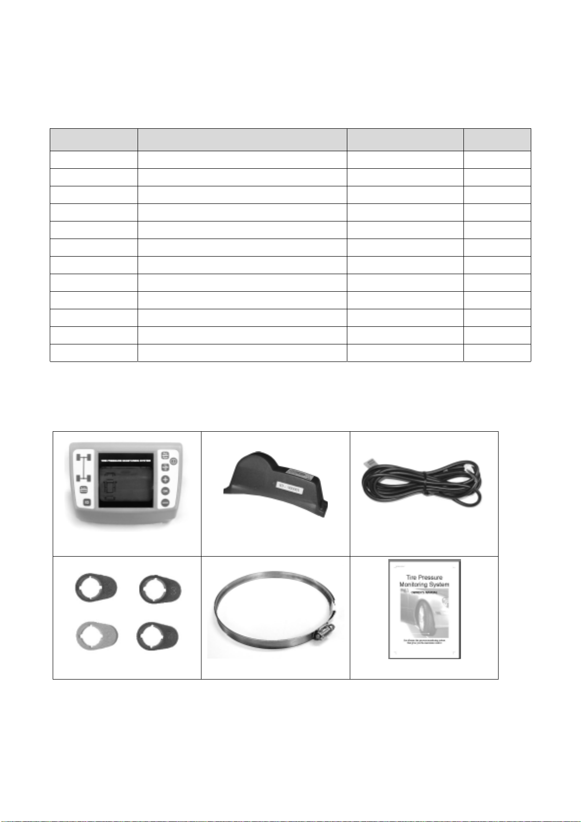
2. Component Part Code List
After unpacking, ensure that all the parts listed below are available. Should any part(s) is/are found missing,
please return to your dealer and get a complete replacement set.
Item Description Part Code Quantity
1 TPMS DISPLAY MODULE ASSY 70-08-01-001-0 1
2 TPMS SENSOR MODULE ASSY#1 70-08-01-002-0 1
3 TPMS SENSOR MODULE ASSY#2 70-08-01-003-0 1
4 TPMS SENSOR MODULE ASSY#3 70-08-01-004-0 1
5 TPMS SENSOR MODULE ASSY#4 70-08-01-005-0 1
6 TPMS 9FT POWER CABLE ASSY 70-08-02-001-0 1
7 SENSOR TAG - RED (#1) 02-09-00-001-0 1
8 SENSOR TAG - YELLOW (#2) 02-09-00-002-0 1
9 SENSOR TAG - BLUE (#3) 02-09-00-003-0 1
10 SENSOR TAG - GREEN (#4) 02-09-00-004-0 1
11 SENSOR CLAMP 72" 06-06-00-009-0 4
12 TPMS OWNER'S MANUAL 08-09-01-001-0 1
Table 3
For replacement parts, quote the description, part code and quantity required when ordering.
Item 11
Item 6
Item 12
Item 1
Item 7, 8, 9 & 10
Item 2, 3, 4 & 5
Page 4
 Loading...