

Strong Frontier TE800-T Owner's Manual

08-09-01-007-0
Tire Pressure
Monitoring System
OWNER’S MANUAL
An advance tire pressure monitoring system
that gives you the maximum control

Page 19
This Page is Intentionally Left Blank
i
TABLE OF CONTENTS
Notices ……………………………………………………………………………..….……………...
FCC Notice
System Scope of Use and Warnings
System Installation and Usage
Reacting To Alerts
Use of Chemicals
Page 1
1. Technical Specifications …………………………………………………………………………….
Sensor/Transmitter Module
Display/Receiver Module
Page 2
2. Components Part List ……..………………………………………………………………………... Page 3
3. Getting Started ……………………………………………………………………………………….
How it works
Handling Alerts
Page 4
4. Sensor/Transmitter Module …………………………...………………………….………………...
Installation
Tools Required
Installing Sensor/Transmitter Module….………………………………………………….
Page 5
Page 6
5. Display/Receiver Module ………………………………...…………………………………………
LCD Display
Installation
Recommended Installation for Display / Receiver Module.……………………………...
Page 7
Page 8
6. Programming ………………………………………………………………………………….……….
Display Mode (S-1)…………………………………………………………………………..
Programming Threshold Setting (S-2)……………………………………………………..
Sensor ID Exchange Mode (S-3).………………………………………………………….
Sensor ID Learning Mode (S-4)….…………………………………………………………
Turn Backlight On/Off (S-5)……...………………………………………………………….
Activate Spare Tire On/Off (S-6)..……………….…………………………………………
Page 9
Page 10
Page 11
Page 12
Page 13
Page 14
Page 14
7. Troubleshooting ……………………………………………………………………………………….
Page 15
8. Appendix & Glossary …………………………………………………………………………………
Page 15
9. Annex …………………………………………………………………………………………………..
Page 16
The manufacturer reserves the right to change the contents of this manual at any time without prior notice. The information
contained in this manual is proprietary and must not be reproduced without prior consent from the manufacturer.

Page 17
This Page is Intentionally Left Blank
Page 2
1. TECHNICAL SPECIFICATION
Sensor / Transmitter Module
Operating Temperature Range
-40°C to +125°C
Operating Humidity 100%
Weight 32 gram
Size (LxWxH) 71 mm x 36 mm x 21 mm
Battery Life (Projected) 5 years in normal use
Transmitting Frequency 433.92 MHz
Transmitter Activation By pressure change
Table 1
Display/Receiver Module
Power Supply 9 ~ 15 V DC
Current Consumption 18mA nominal, 130mA during alert @ 12V DC.
Operating Temperature Range
-40°C to +85°C
Weight 93 gram
Size (LxWxH) 18mm x 125mm x 33mm
Receiving Frequency 433.92 MHz
Monitored Temperature Range
-40 ~ 125°C (-40 ~ 257°F)
Monitored Pressure Range
0 ~ 500 Kpa (Accuracy: ± 10 Kpa)
0 ~ 73 Psi (Accuracy: ± 1.5 Psi)
Table 2
Page 15
7. Troubleshooting Guide
8. Appendix
Glossary
Kpa Pressure reading in kilo Pascal
Psi Pressure reading in pound per square inch
Bar Pressure reading in bar
°C Temperature reading in degrees Celsius
°F Temperature reading in degrees Fahrenheit
Cold Pressure
Recommended inflation pressure of a tire at ambient temperature of 22°C by
vehicle manufacturers.
Low Pressure Alert Visual and audible warning that is activated when the tire’s pressure goes
below the preset level.
Initial Low Pressure Alert Visual and audible warning activated when tire pressure reaches the region
of 50Kpa before Low Pressure Alert (e.g. Factory setting, Low Pressure Alert
is set to 120Kpa, which means Initial Low Pressure Alert is when pressure is
above 120Kpa, but below 170Kpa.
Display/Receiver Module The electronic module mounted inside the vehicle that alerts the driver of any
tire irregularities.
Sensor/Transmitter Module The electronic module mounted on the wheels that measure the air pressure
and temperature of the tire.
Symptoms Possible cause(s) Solution
No display on LCD panel. No power. Check connections of Power cable at both
ends. Ensure that the connection is on the
correct polarity and properly grounded.
No display on LCD panel. Faulty Unit. Contact your dealer for a replacement.
The unit does not activate when the
POWER key button is pressed.
The car ignition has not
been turned ON.
Turn the ignition key to ACC position.
The receiver is not learning the ID
during ID LEARNING Mode.
Localize RF interference. Move to another location and re-initiate the
ID LEARNING process.
No instant alert Reverse power cable
installation.
Ensure that the red wire is connected to
permanent power supply (battery) and
orange wire is connected to ACC position of
the ignition.
Unable to tighten screw into the tire
valve
Check tire valve thread Change tire Valve
Air cannot be pump into the tire No centre holes on the
valve screw
Change to Valve Screw M5x20 with centre
holes
Page 4
3. GETTING STARTED
How it works
Pressure and temperature information are sent to the Receiver and displayed on the LCD display. When an underinflated, over-inflated or over-heated tire is detected, the Receiver will emit an audible warning and activate the
backlight to warn the driver. The al erts depend on threshold val ue set for pressure and temperature. Either the
factory or manual preset value can be selected.
Handling Alerts
When any of the tires is not within the threshold limits (e.g. under inflated or over heated, the following will occur:
• An audible warning will be activated for a period of 10 seconds at the first occurrence.
• The backlight of the LCD display would be activated for 20 seconds at the first occurrence.
• Low/High Pressure Alert: Pressure Alert indicator (Yellow) of the module turn On permanently.
• Initial Low Pressure Alert: Pressure Alert indicator (Yellow) of the module will blink.
• High Temperature Alert: Temperature Alert indicator (Yellow) of the module turns On permanently.
• Tire icon will blink at the faster rate.
The above conditions will persist until the threshold returns to their corresponding preset value.
All TPMS unit comes with the following factory-preset value:
a. Initial Low Pressure Alert when tire pressure is greater than 120Kpa but lesser or equal to 170Kpa (50Kpa
before Low Pressure Alert)
b. Low Pressure Alert when tire pressure is lesser or equal to 120 Kpa (23 Psi)
c. High Pressure Alert when tire pressure is greater or equal to 300 Kpa (44 Psi)
d. High Temperature Alert when tire temperature is greater than 80ºC (176ºF)
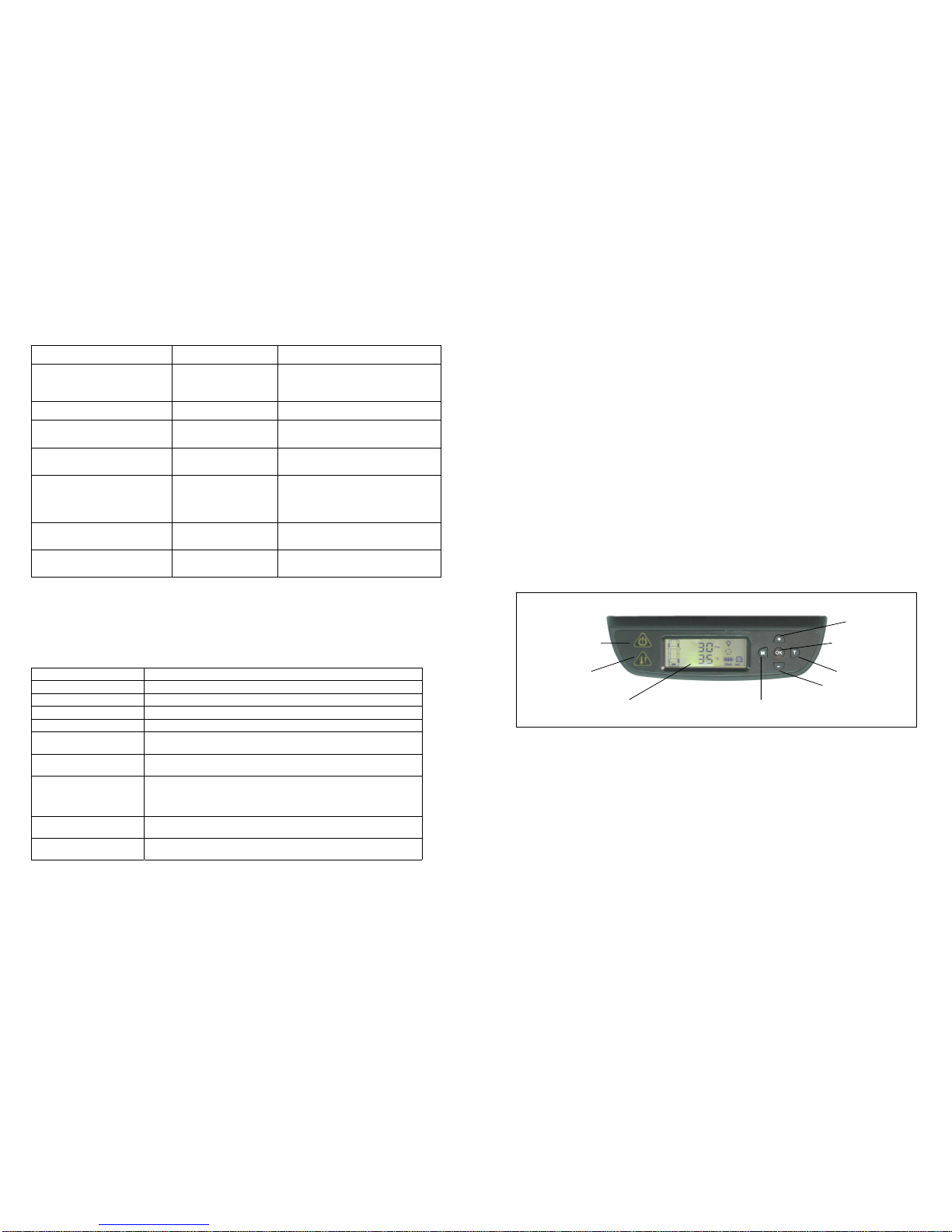
Figure 1 Display/Receiver Module
Pressure Alert Indicator
Temperature Alert
Indicator
LCD Display
Increment Value /
Kpa / Bar / Psi
OK key / Power On/OFF
Tire Select
Decrement Value /
°C / °F
Mode Select
 Loading...