

Page 1

--Specifications--
Wing span: 78” w/tips
Wing area: 1145 sq. in
Length: 70.5"
All up flying weight: 11.5lbs
Page 2
STRONG DESIGNS RW EDGE 540V3 30CC
Needed to complete:
Engine- 30cc-40cc 2-stroke (DLE 35ra / PTE 36
or VVRC 40 w/ ¼-32 plugs)
19x8-20x9 prop
Servos- (6) Standard size servos (min 250oz/in)
Batteries- (2) 1100-2000mah 6v min
Radio System (Min 5ch)
Optical Kill switch
(2) power switches
3” spinner
Tygon fuel line
Adhesive backed Velcro
Velcro strap
Zip ties
Servo Extensions
Tools and adhesives needed:
Hobby knife
Sealing iron
Allen driver set
Phillips head driver
Adjustable wrench
Forceps
Pen
Low tack Painter’s Tape
5 min and 15 or 30 min epoxy
Petroleum Jelly
Thin and medium CA
Medium thread locker
Drill with bits
Denatured Alcohol
Begin by removing everything from the box
and inspecting for damage or any missing parts.
If there are any damaged or missing parts
please contact RedwingRC immediately.
Before any assembly begins, read over the
manual and make sure you have everything you
need on hand, this will make the assembly go
much faster. It is a good idea to go over all the
seams and shrink any sags in the covering with
a sealing iron set to a moderate temperature
(280 - 300 degrees). - This will be much easier
before assembly and will ensure the seams are
locked down to avoid separation.
From the Pro: Go over all the edges of the color
scheme with trim solvent using a cotton ball. This will
lock the edges into place.
2
Page 3
STRONG DESIGNS RW EDGE 540V3 30CC
Wing Assembly
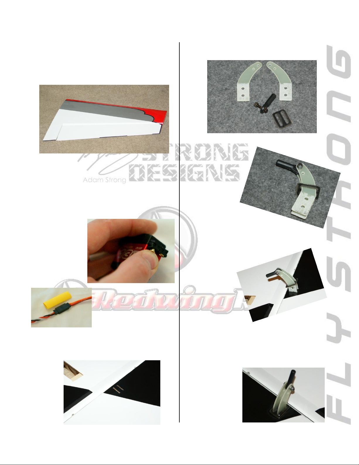
The ailerons arrive pre-hinged. Firmly pull on
the aileron to ensure all hinge points are
secured properly.
From the Pro: Some pilots prefer to seal the hinge
gap. If you wish to do this, it is best to do it now
before anything is installed to the wing.
•Prepare the aileron servos by installing the
grommets and inserts. Also, secure the
extension to
the lead at this
time.
From the Pro: Use heat shrink
tube to secure the servo lead
to the extension.
•Next, install the dual control horns into the
pre-cut slots of the ailerons.
•Lightly scuff the glue surface of the horns using
coarse grit sand paper or a rotary sanding tool.
•Using the
included linkage
hardware, join
the two horns as
shown.
•Mix a small batch of 15 min
epoxy and coat the
inside of the slots.
Lightly coat the ends
of the control horns
and insert them into
the slots, angled
toward the hinge line.
•You should have minimal squeeze out and a
small fillet will form at the base of the horns.
Clean up any excess with denatured alcohol.
3
Page 4
STRONG DESIGNS RW EDGE 540V3 30CC
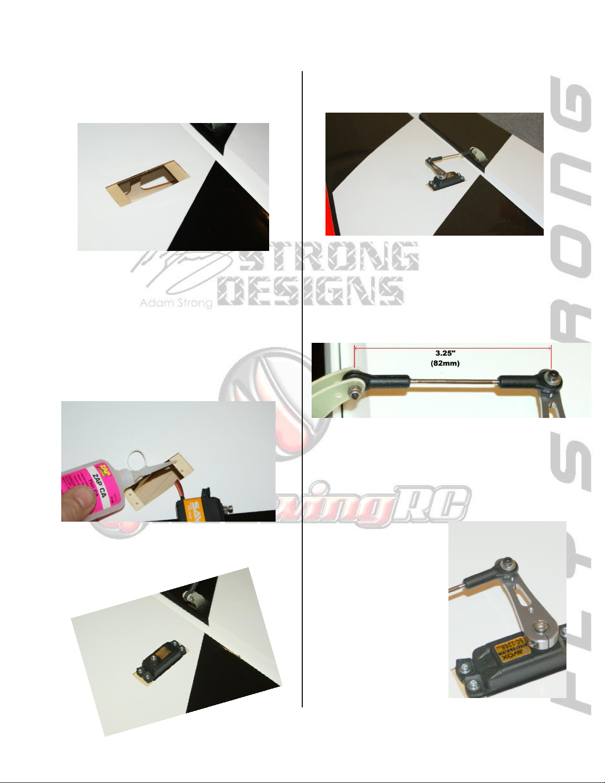
•Locate the servo pocket and remove the
covering. Then drop the servo into place and
drill for the servo screws with a 1/16” drill bit.
From the Pro: When removing the covering leave
1/8-1/4” of covering to be ironed down into the
servo pocket. This makes for a much cleaner and
more fuel-proof servo cut-out.
•Remove the servo and thread a servo screw in
and out of each hole. Then apply 2 drops of thin
CA to each and allow the CA to soak in and fully
cure.
•Center the servo and install the servo horn
pointing toward the wingtip, aligning with the
control horn.
•Assemble the control rods to 3.25” length
making sure the turnbuckle is centered with
room to adjust both ends.
• Install the pushrod using the included
hardware.
•Install the servo with the output to the leading
edge, pulling the wire lead out to the root of
the wing.
From the Pro: It is best practice to use a small
washer on the outside of the ball link on the servo.
This will prevent the ball joint
from slipping off under load.
4
Page 5
STRONG DESIGNS RW EDGE 540V3 30CC
Horizontal Stabilizer and Elevator
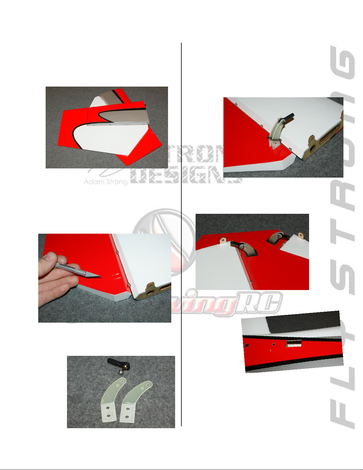
•The elevators arrive pre-hinged. Firmly pull on
them to ensure all hinge points are secured
properly.
From the Pro: Some pilots prefer to seal the hinge
gap. If you wish to do this, it is best to do it now
before anything is installed to the elevator.
•Locate the slots for the elevator control horns
and open them using a hobby knife.
•Scuff the glue surface of the control horns
using coarse grit sand paper or a rotary sanding
tool.
•Using the included linkage hardware, join the
two horns as shown. Then mix a small batch of
15 min epoxy and coat the inside of the slots.
Lightly coat the ends of the control horns and
insert them into the slots, angled toward the
hinge line.
•You should have minimal squeeze out and a
small fillet will form at the base of the horns.
Clean up any excess with denatured alcohol.
•While the control horn cures, locate the servo
pockets on the
fuselage sides
and remove the
covering with a
hobby knife.
From the Pro: When removing the covering leave
1/8-1/4” of covering to be ironed down into the
servo pocket. This makes for a much cleaner and
more fuel-proof servo cut-out.
5
Page 6
STRONG DESIGNS RW EDGE 540V3 30CC
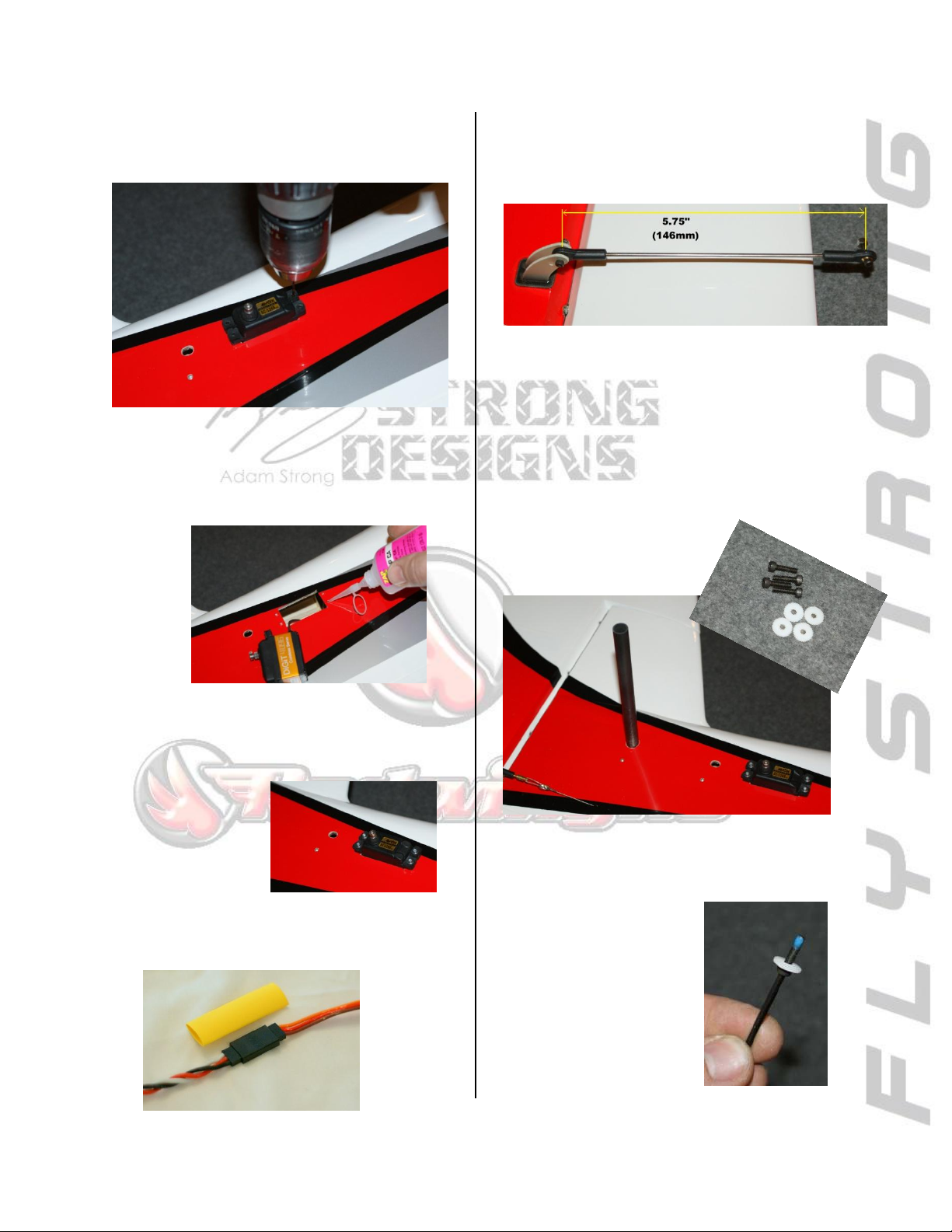
•Next drop the servo into place and drill for the
servo screws with a 1/16” drill bit.
•Remove the servo and thread a servo screw in
and out of each hole. Then apply 2 drops of thin
CA to each and allow the CA to soak in and fully
cure.
•Next, install the servo with the output to the
rear, pulling the wire lead into the fuselage
from the radio tray.
Then center the
servo and install the
servo horn.
From the Pro: Use heat shrink tube to secure the
servo lead to the extension
•Assemble the control rods to 5.75” length
making sure the turnbuckle is centered with
room to adjust both ends, and secure the
elevator end.
NOTE: It is easier to install the rudder,
tailwheel, and pull-pull linkage before mounting
the Horizontal stabs to the fuselage.
•Next, insert the carbon fiber stabilizer tube to
the fuselage. DO NOT GLUE!
Then locate the stabilizer
hardware.
•Install the stabilizer
halves onto the carbon
fiber tube, and secure
using the screws with a
drop of thread locking
compound on each.
6
Page 7
STRONG DESIGNS RW EDGE 540V3 30CC
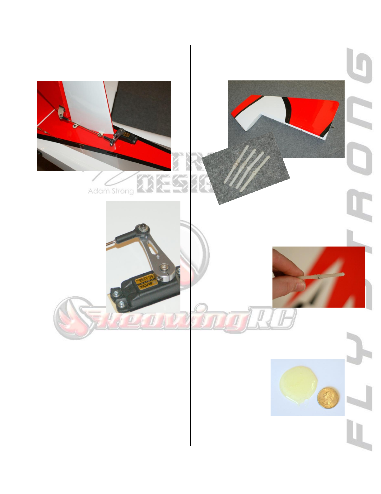
• Once the horizontal stabilizer is installed to
the fuselage, center the servo and connect the
servo end with the included hardware.
From the Pro: It is best practice to use a small
washer on the outside of the ball link on the servo.
This will prevent the
ball joint from
slipping off under
load.
.
Rudder and Tail Wheel
Start by removing all the hinge points from the
rudder.
Coat the pivot of each hinge with petroleum
jelly all the way around working the hinge back
and forth to ensure full
coverage into the
pivot.
NOTE:
Keep clear of the
ribbed portion as this
will prevent adhesion.
You will install the point hinges into the
fuselage side first.
•Mix a small batch of
30 minute epoxy
(about 1 to 2 quarter’s
size)
7
Page 8
STRONG DESIGNS RW EDGE 540V3 30CC
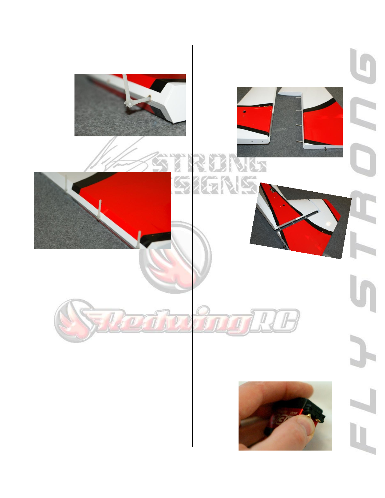
•Using a toothpick, apply epoxy into each hinge
point bore. Then coat one end of the point
hinge with epoxy to install.
NOTE: Make sure to align the hinges by flexing
them to the side 90 degrees and fully inserting.
You should have some epoxy squeeze-out as
the pin is inserted. Be careful to pull the excess
epoxy away from the hinge point and not work
it into the pivot.
NOTE: Excess Epoxy is easily removed with
denatured alcohol before it cures.
From the Pro: To make things easy, use a Q-tip to
clear epoxy from around each hinge point as it is
installed.
•Install all the hinge points and set aside to
cure.
From the Pro: While the epoxy is curing, it is a great
time to skip ahead and start installing the control
horns.
•Once cured, mix another batch of epoxy and
coat the inside of each hinge point bore as
before. Then stand out the hinge points, and
coat the end of each.
•Carefully align the hinge pins to the bores as
you install to the fuselage and remove any
excess epoxy
with denatured
alcohol.
•Ensure the rudder moves freely bevel to bevel
to allow maximum deflection and set aside to
cure.
From the Pro: Use a few pieces of painters tape to
secure across the hinge line as it cures to ensure a
tight hinge line.
•Prepare the rudder servo while the epoxy is
curing. Install the grommets and inserts and
secure the extension to the lead at this time
and set
aside.
8
Page 9
STRONG DESIGNS RW EDGE 540V3 30CC
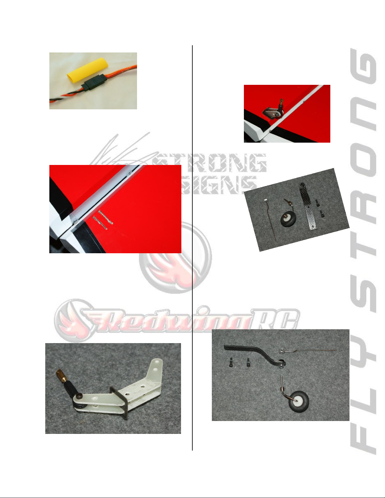
From the Pro:
Use heat
shrink tube to
secure the
servo lead to
the extension.
•Once the epoxy is cured, locate the control
horn slots on the rudder and open them using a
hobby knife.
•Scuff the glue surface of the horns using
coarse grit sand paper or a rotary sanding tool.
•Using the linkage hardware, join the two horns
as shown and test fit to make sure they fully
seat in the slots of the rudder.
•Then mix a small batch of 15 min epoxy and
coat the inside of the slots. Lightly coat the
rudder control horns and insert them into the
slots, angled toward the hinge line as shown.
•Clean up
any squeeze
out with
denatured
alcohol.
•Next,
locate the
tail wheel
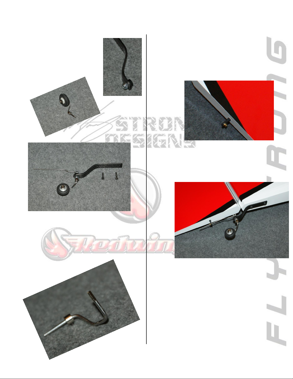
hardware.
•The parts will assemble as laid out below - -
9
Page 10
STRONG DESIGNS RW EDGE 540V3 30CC
•Install the tailwheel bushing
to the carbon fiber mount.
Then install the wheel to the
wire using the wheel collar
and then secure the assembly
using the upper retainer.
From the Pro: File a flat spot for the wheel collar on
the wire and use medium thread locking compound
to install the setscrews.
•Next install the tiller pin into the rudder. Drill
a 1/8” hole in the bottom of the rudder 3.5"
back from hinge line. Clean the tiller pin with
alcohol and coat inside of the hole in the rudder
15 min epoxy and insert the end of the pin.
•There are blind nuts preinstalled for the
tailwheel bracket. Locate the blind nuts, align
the tailwheel assembly and install the screws
using a thread locking compound.
NOTE: You may need to bend the tiller wire a
bit for alignment.
10
Page 11
STRONG DESIGNS RW EDGE 540V3 30CC
Rudder Servo and Pull-Pull
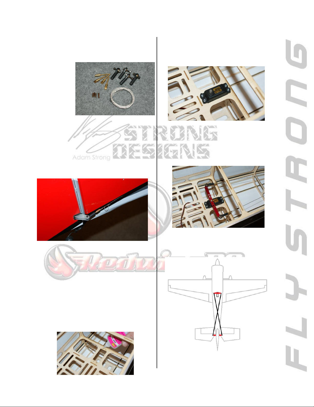
•Locate the pull-pull hardware - - one set of
links should already be installed to the rudder.
•Route the pull-pull cables from the slots in the
rear of the fuselage to the rudder servo tray. At
the rudder, slide a crimp onto the wire and loop
the cable thru the link and back into the crimp
with a loop as shown to hold the end in place
for each side.
DO NOT CRIMP YET!
NOTE: Make sure the ball link is threaded in the
center of the adjustment range (about ¾ of the
thread) to allow even adjustment.
•Drop the servo into place and drill for the
servo screws with a 1/16” drill bit.
•Remove the servo and thread a servo screw in
and out of each hole. Then apply 2 drops of thin
CA to each and allow the CA to soak in and fully
cure.
•Install the servo with the output to the front of
the fuselage and center using the radio.
• Install the links to your servo horn using the
included hardware. Then, install and crimp the
cables in place on the servo end as shown - -be
sure to leave the excess on the rudder end.
NOTE: The cables should cross inside the
fuselage as shown when installed to the servo
horn.
11
Page 12
STRONG DESIGNS RW EDGE 540V3 30CC
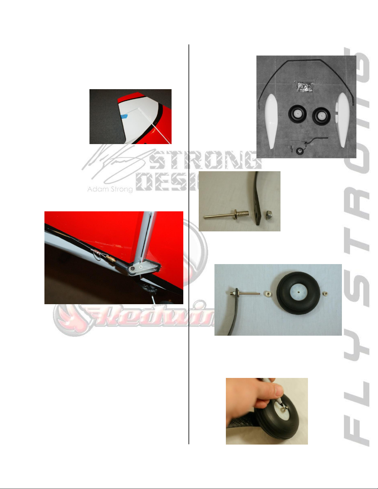
•Next, place a piece of masking tape at the
rudder counter balance to lock the rudder in
the centered position. Then power on the radio
to lock the rudder servo in the center position
and install the servo horn.
•With the links already secured to the servo
horn, tighten the cables at the rudder. Make
sure the cable loop at the servo is pulled
straight and the cable is reasonably tight then
crimp the rudder end of each cable.
Main Landing Gear
•Locate the
landing gear
hardware and
assemble the
main gear as
follows.
•First, install the
axles using the
provided lock
nut.
•Then, assemble the wheel and collars to the
axle in the order shown.
From the Pro: If you make a mistake on the pull-pull
setup and ruin a cable, you can use 60lb-test fishing
leader line and crimps found at your local outdoor
sports retailer as a replacement.
NOTE: The inner wheel collar will properly
space the wheel for the wheel pant.
•Next, mark the axle at the outside of the wheel
collar.
12
Page 13
STRONG DESIGNS RW EDGE 540V3 30CC
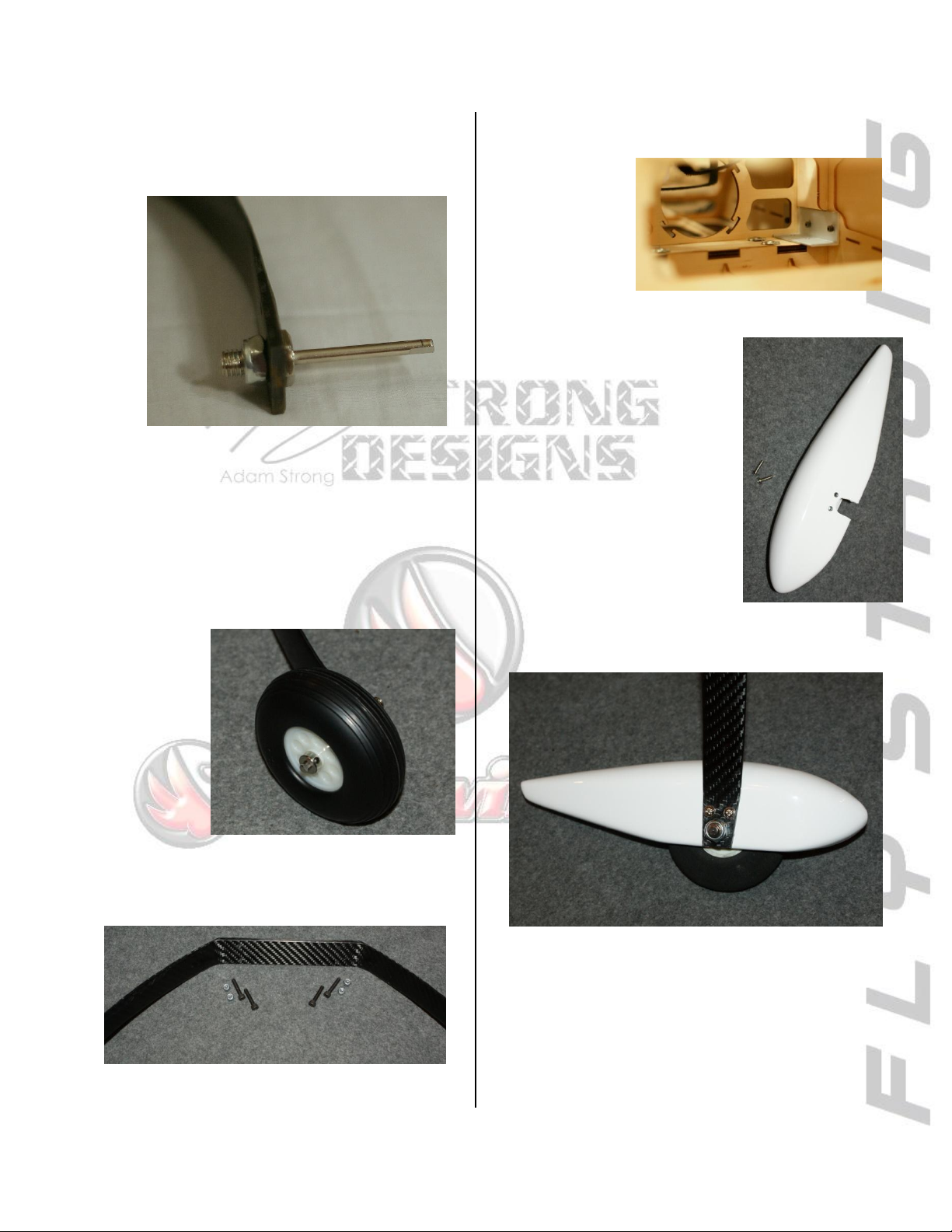
•Trim the axle, leaving the mark visible allowing
1-2mm excess to remain and file a flat as shown
for the wheel collar.
From the Pro: Locating the flat on the bottom of the
axle will allow easy access once the wheel pant is
installed.
•Install the wheel to the axle for the final time
using medium thread lock compound on the
setscrews.
•Locate the landing gear hardware and secure
the gear to the fuselage.
From the Pro: install the rear-most nut and bolt first
on each side to avoid the front nut from being in the
way of tightening
the rear.
•Locate the wheel pants and
screws.
•The blind nuts are
preinstalled, simply align the
holes and mount the wheel
pants using the supplied bolts
and washers with medium thread lock
compound.
13
Page 14
STRONG DESIGNS RW EDGE 540V3 30CC
Engine Installation
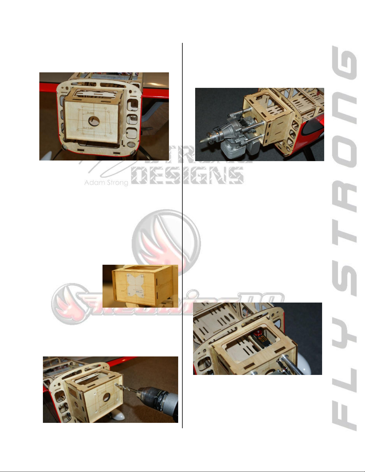
•The firewall comes marked for the DLE 35RA
and DLE 40 twin.
NOTE: The DLE40 Twin will NOT fit inside the
cowl without the plug caps showing. A better
choice is the VVRC 40cc Twin with the ¼-32
plugs.
•If using a different engine, align your motor’s
mounting template with the centering marks on
the firewall and secure in place with tape if
needed.
From the Pro: Cutting toward the center of the
template as shown
will make alignment
easier and more
precise.
•Once aligned, drill the mounting holes with the
proper size bit for the mounting bolts and
remove the template.
•Next, temporarily mount the motor in place to
mark for the throttle linkage, fuel lines, and any
ignition cable routing.
•Check the engine’s spacing by measuring from
the firewall to the front of the engine’s prop
hub. Proper spacing is 6 3/8" (162mm) from
the firewall.
--The DLE stock standoffs work perfectly.
•Next determine where you will need to mount
the throttle servo to properly align with the
carburetor. You may find you need to rotate
the carb or modify the throttle arm for proper
geometry.
14
Page 15

STRONG DESIGNS RW EDGE 540V3 30CC
NOTE: A
gusseted
mount is
included
and can
be mounted anywhere in
the forward fuselage
using 15 min epoxy.
Ensure you do not
interfere with the position of the other
components that will be
installed later such as the fuel
tank and
ignition.
--For a Twin, the low carb position requires a
lower mounting of the
throttle servo as shown
in the floor of the motor
box.
•Determine the mounting position and prepare
the servo. Install the grommets, inserts, and
secure the extension to the lead at this time.
From the Pro: Use heat shrink
tube to secure the servo lead to
the extension.
•Drop the servo into place and drill for the
servo screws with a 1/16” drill bit. Then,
remove the servo and thread a servo screw in
and out of each hole. Then apply 2 drops of thin
CA to each and allow the CA to soak in and fully
cure.
•Before installing the throttle linkage,
determine the position of the ignition module,
fuel line routing thru the firewall, and choke
linkage so that you may remove the engine and
drill all holes needed at the same time.
•Once all holes have been drilled, you may
reinstall the engine for final assembly using
thread lock compound.
•Install the throttle servo and the linkage to the
carburetor.
From the Pro: The throttle arm on the carb and the
servo horn should be of the same length to allow full
servo resolution and better/finer throttle control.
15
Page 16
STRONG DESIGNS RW EDGE 540V3 30CC
Ignition Module
•Choose a location for the ignition model a few
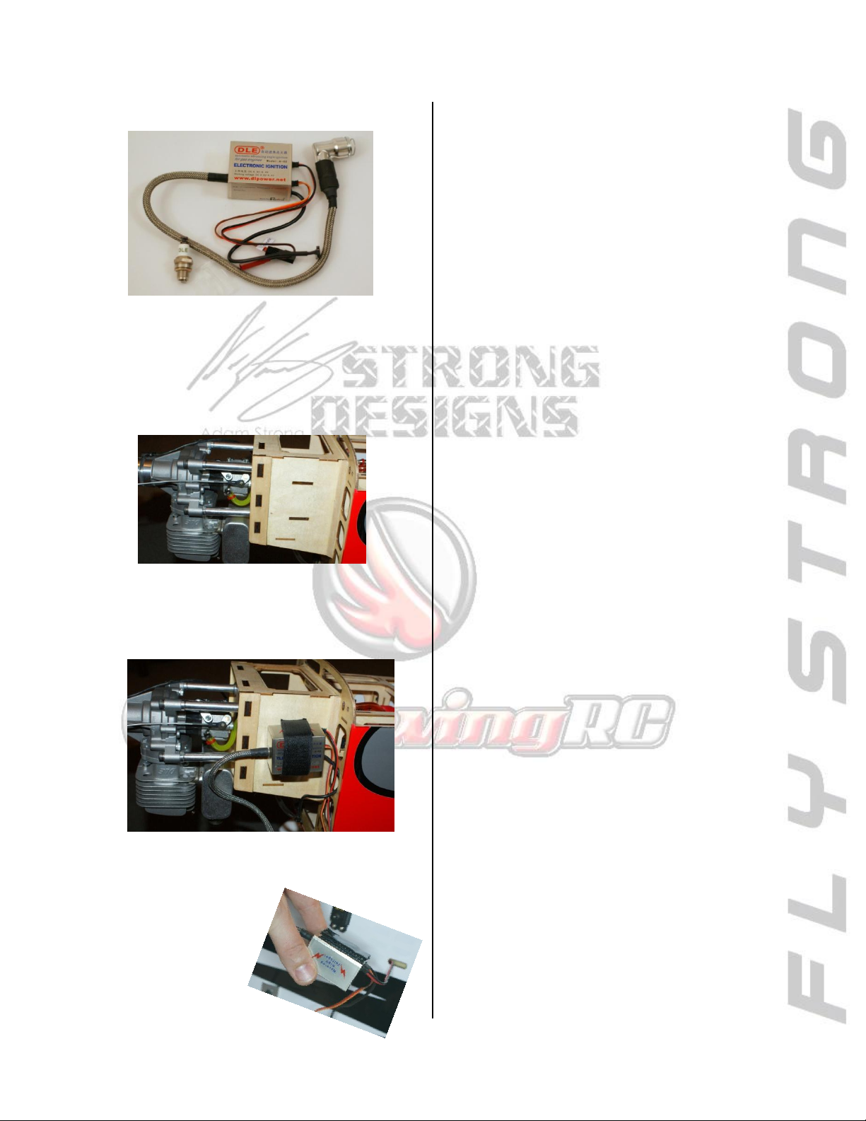
inches or more away from the throttle servo if
possible. There are precut slots on the motor
box to secure the ignition module on the side.
•Secure into position using sticky backed Velcro
and secure with the included Velcro strapping.
•Route the leads to the plug and hall sensor
using the wire loom supplied with the engine as
needed.
NOTE: While not required the use of an
electronic kill switch is strongly recommended.
From the Pro: Layer the Velcro to create a soft
mount and do not over tighten the straps. A
loose but secure mount
will lessen vibration
to ensure long life of
the module.
16
Page 17
STRONG DESIGNS RW EDGE 540V3 30CC
Fuel Tank
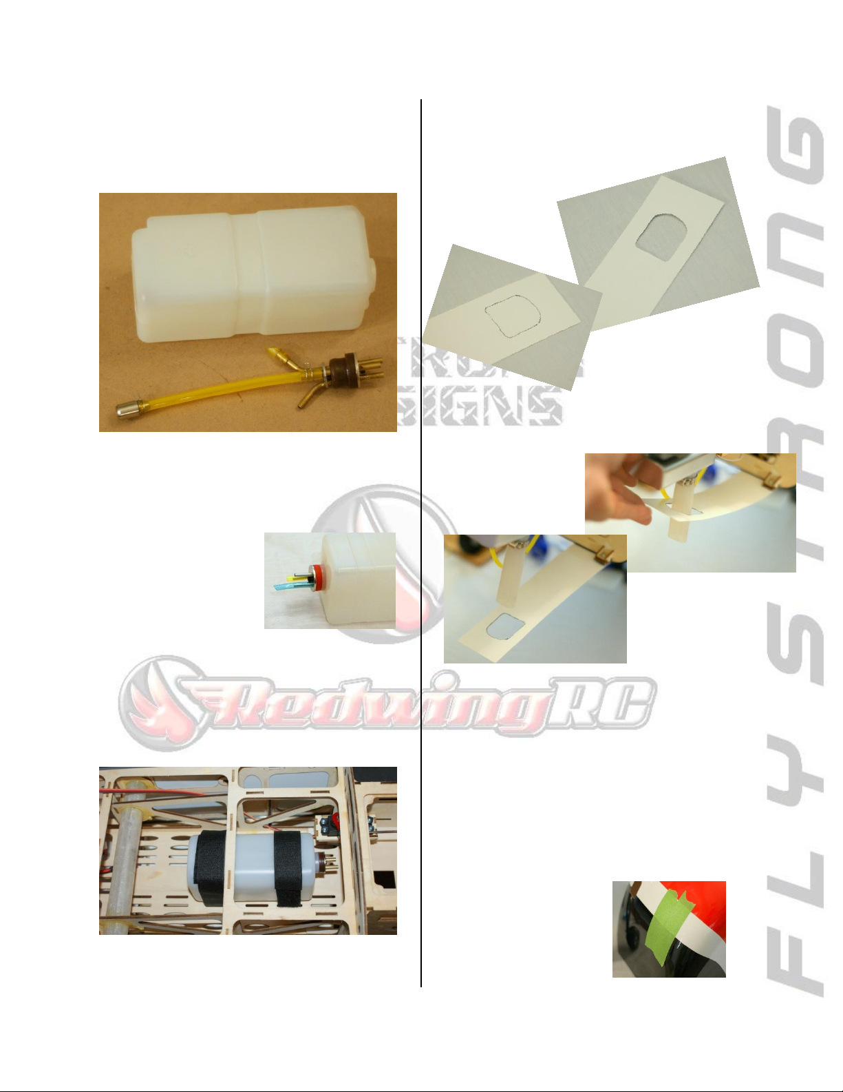
•The fuel tank comes pre-assembled, remove
the stopper and verify everything is correct.
•The fuel tank utilizes a 3-line setup and is
configured as shown above inside the tank.
From the Pro: Mark the
top of the fuel tank and
label or color code the lines
to avoid confusion after
you secure the assembly
into the fuel tank.
•Tighten the stopper into the tank. Then secure
into the fuselage using the straps provided and
route the fuel lines.
Cowl Installation
•First make templates for each cut-out of the
cowl – typical muffler
tube templates
shown.
•Once you have templates made for each of the
cutouts, tape them in place on the fuse to
properly locate the
cowl cutout.
•Next, remove all items that require a cutout
and install the cowl. – this may mean removing
the engine or muffler(s) again.
NOTE: The cowl ring should be fully seated on
the fuselage and will properly align the cowl.
From the Pro: Use masking
tape on all areas to be
marked on the cowl. This
allows you to easily see the
lines making for a cleaner
cutout.
17
Page 18
STRONG DESIGNS RW EDGE 540V3 30CC
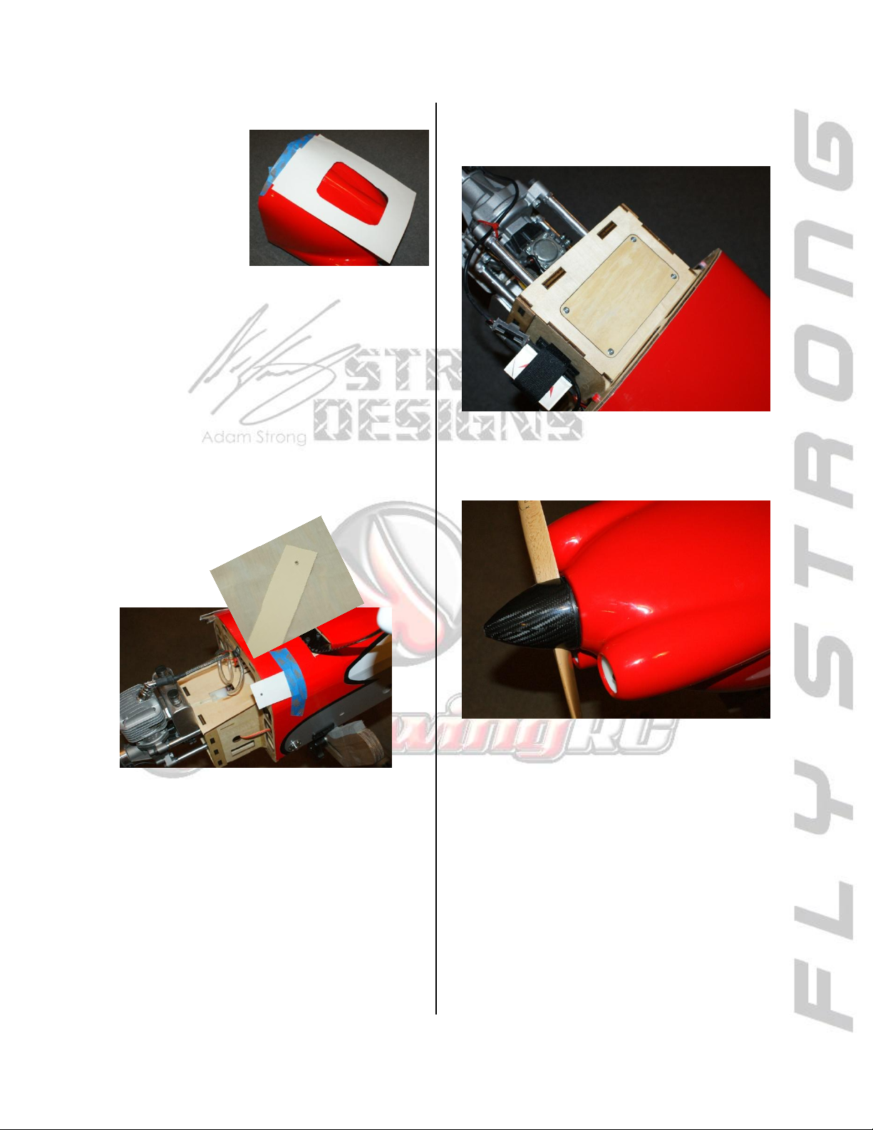
•Mark all the
cutouts on the cowl.
Then, remove the
cowl and trim using
a rotary tool.
•After the initial cutouts are complete, test fit
and adjust as needed until the cowl fits without
any rubbing and a minimum 1/8” clearance .
From the Pro: Make only small adjustments at a time
as you can quickly remove too much material.
•With the cutouts finished, make a template for
the lower cowl screws. Align with the screw
hole using one of the
mounting screws before
taping in place.
•Install the cowl for the final time using thread
lock compound and bonded washers on all the
screws .
•Finally, you can install the prop and spinner to
finish up the nose.
•Install the cowl, mark the mounting locations,
and remove to drill. Drill a 1/8” hole in each
location.
•Before installing the cowl the final time, install
the top cover for the motor box. Harden the
screw threads with thin CA as you have done for
the servos throughout assembly.
18
Page 19
STRONG DESIGNS RW EDGE 540V3 30CC
OPTIONAL:
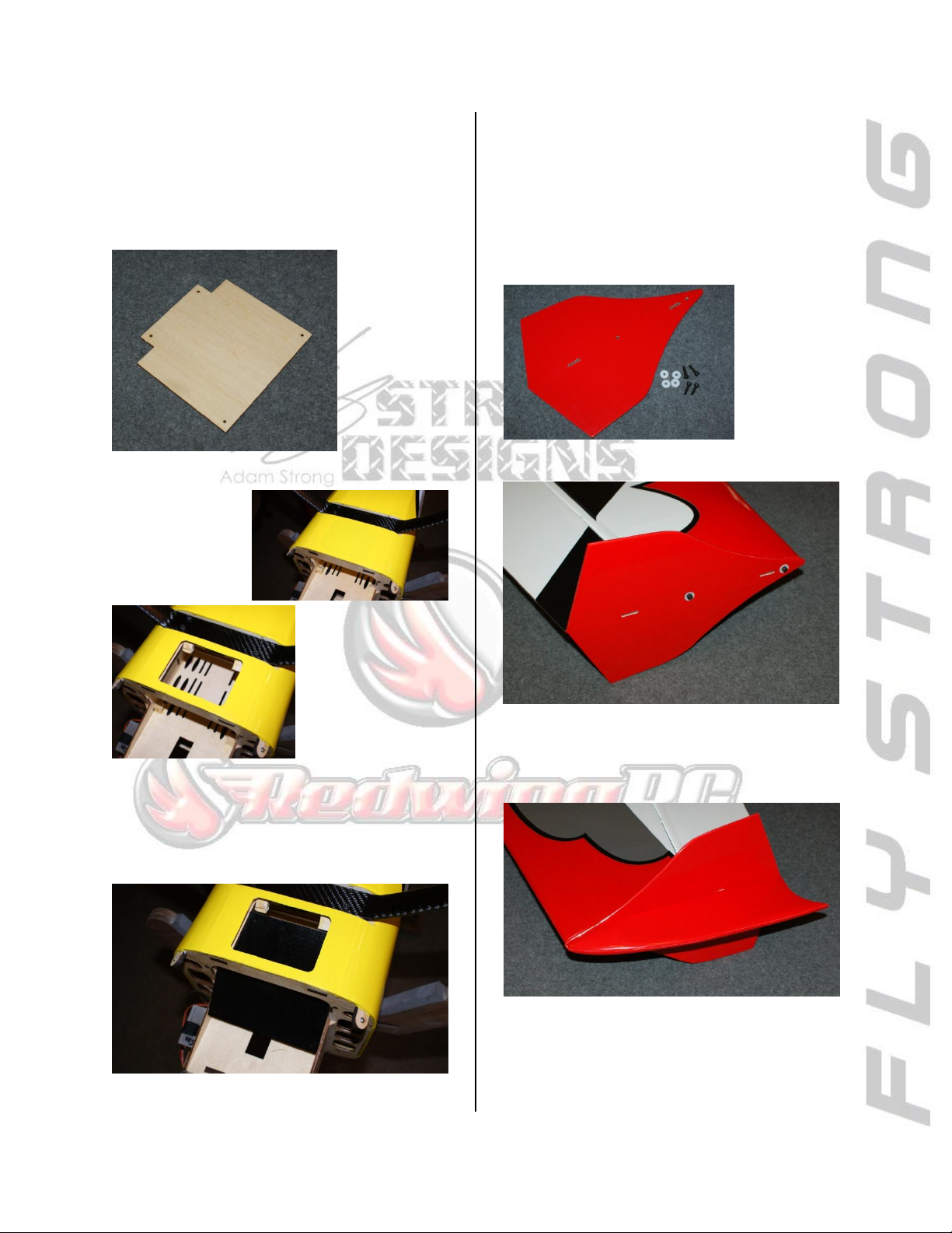
Air Dam
•Included in the kit is an air dam to divert the
air from the cowl thru a cutout in the forward
fuselage ahead of the landing gear.
•Remove the covering from the outlet.
SFG’s and Wing Tips
•Install the side force generators (SFG’s) and
wing tips to the wing. The SFGs are installed
using the screws provided with a drop of thread
locking compound on each screw. There are
blind nuts preinstalled in each wing tip.
•Predrill the holes for the plate and thread
them using the include mounting screws.
Harden the threads with thin CA before final
installation.
•The wing tips are easily secured with magnets
and tabs which lock them in place.
NOTE: If using the tips, make certain the SFG is
installed facing correctly to maintain proper
polarity of the magnets to the tips.
19
Page 20
STRONG DESIGNS RW EDGE 540V3 30CC
Receiver and Setup
The receiver will typically be located behind the
wing tube support or on the rudder servo tray
with the batteries placed to achieve the proper
balance of the model. Make all connections and
use a soft mounting to help isolate from
vibration.
Center of Gravity
For your first flights set the CG 5.25” from the
leading edge at the root of the wing. This is
near the front of the wing tube and will be close
to neutral. After checking the CG in flight you
can adjust for your personal flying style.
Control throws: -- DR/Expo --
LOW MED HIGH
AIL 1.75”/30% 2.75”/40% 4”/60%
ELE 2.5”/30% 3.25”/ 40% 4”/55%
RUD 2.5”/20% 3”/ 30% 4.25”/40%
NOTES:
______________________________
______________________________
______________________________
______________________________
______________________________
______________________________
______________________________
______________________________
______________________________
______________________________
______________________________
______________________________
______________________________
______________________________
______________________________
______________________________
______________________________
______________________________
______________________________
______________________________
______________________________
______________________________
20
 Loading...