

Page 1
User Manual
DiSEqC Positioner v50
Picture similar
n DiSEqC 1.0 / 1.2 Receivers Compatible
n Work with any Receiver via Optional Remote Control
n Compatible with any Actuator or H-H Mount
n 60 Programmable Memories
n Easy Operation and Quick Installation
n Fine-tune Function for Better Reception
n Anti-Noise Circuit to avoid miscounting
n Short Circuit and Overload Protection
n Software Limits Protection
n Auto Turn-off Function
n Re-Calculate (Adjust Shift) Function
n Lock Key Protection
Page 2

PART 1 • English
* €0.12/Min. from Aust rian wired line
* €0.14/Min. from Germ an wired line
per Januar y 2007
TABLE OF CONTENTS
1.0 SAFETY PRECAUTIONS 2
2.0 OPTIONAL REMOTE CONTROL V.S. RECEIVER 2
3.0 BASIC OPERATION 4
4.0 DIGITS LED DISPLAY 4
5.0 CABLE CONNECTION 5
6.0 FOR ANY RECEIVER 6
7.0 FOR DISEQC 1.2 RECEIVER 8
8.0 TROUBLESHOOTING 1
9.0 QUICK TABLE FOR OPTIONAL REMOTE CONTROL 1
9.0 DISPLAY DESCRIPTION 14
10.0 SPECIFICACTION 14
English
1
3
1
Page 3

PART 1 • English
2
1.0 SAFETY PRECAUTIONS
1. The ventilation should not be impeded by covering the ventilation openings with items,
such as newspapers, table-cloths, curtains, etc.
2. No naked flame sources, such as lighted candles, should be placed on the apparatus.
3. The apparatus shall not be exposed to dripping or splashing and no objects filled with
liquids, such as vases, shall be placed on the apparatus
2.0 OPTIONAL REMOTE CONTROL V.S. RECEIVER
Do you need the optional remote control? It is upon your receiver and how many positions you
want. Please check the following table.
Receiver Type Remote Control Positions Note
DiSEqC 1.2 Not Necessary
60
Fully controlled by receiver.
Yes / Optional
DiSEqC 1.0 No
Yes / Optional
No DiSEqC Yes / Necessary 60 Just like stand-alone positioner
60
4
60
Controlled by receiver or optional remote control
Controlled by receiver.
Controlled by receiver or optional remote control.
Page 4
PART 1 • English
3
English
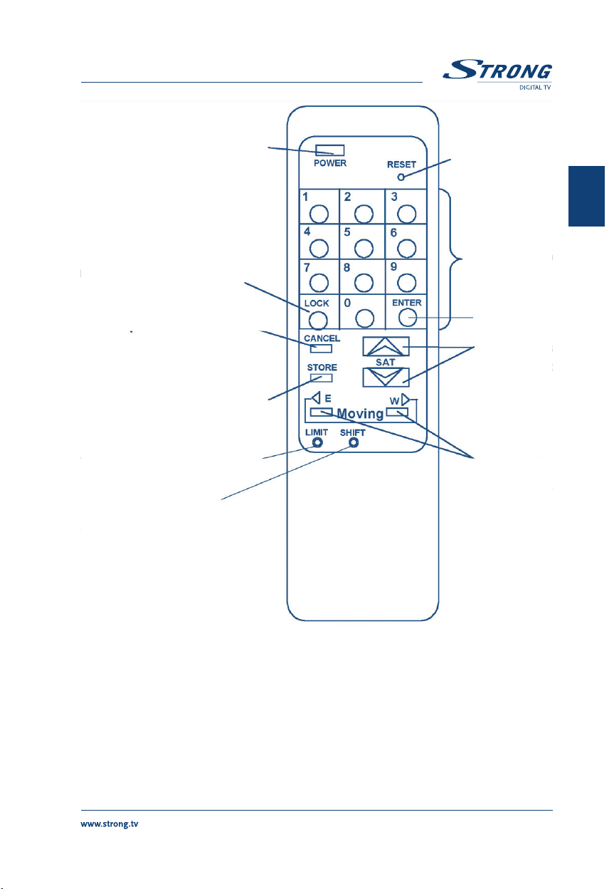
Power On/Off
RESET
Lock/unlock the positioner
Cancel the previous command
Store a Satellite position
Set software east / west limits
Shift: Adjust all the stored
satellite positions
Sat. No. keys
(0-9)
Enter Key
Browse stored
Satellite positions
Manually adjust
direction to
East / West
Page 5
PART 1 • English
4
3.0 BASIC OPERATION
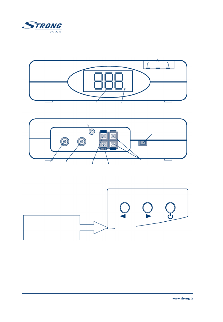
Front View
3 Digit LED Display 1K Indicator
5 V DC (Optional for Optical Sensor
Manual Buttons
Connect to Receiver and LNB
(Via Coaxial Cable)
Manual Buttons
For South Hemisphere:
The East / West buttons
should be exchanged.
Pulse Ground
(Connect to Reed Switch Sensor)
East (
West
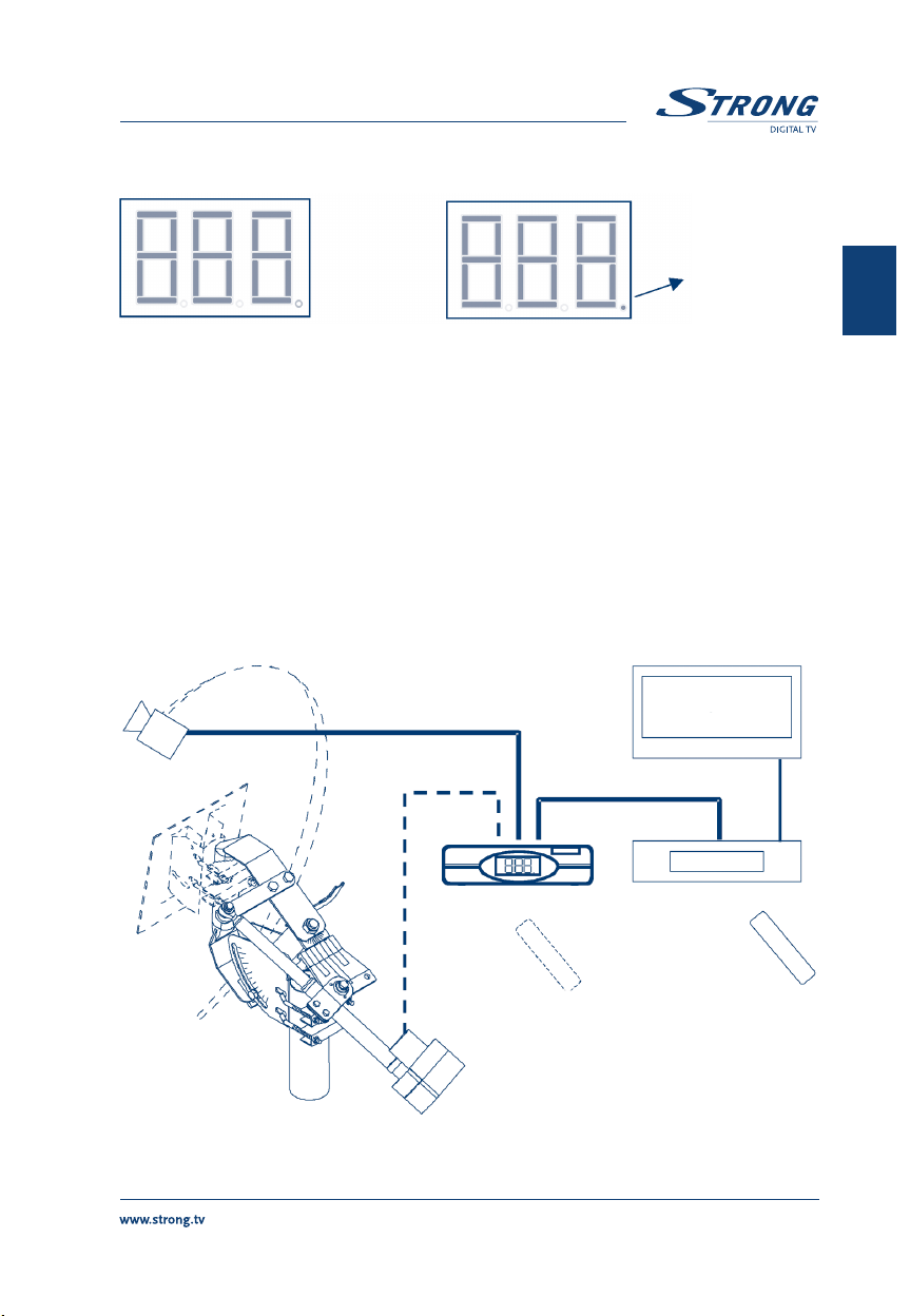
4.0 DIGITS LED DISPLAY
1. The total antenna position Index (pulse counts) is 2,000 (0 ~ 1,999).
2. For Index 0 ~ 999, the lower right dot (1K Indicator) will not light on.
3. For Index 1,000 ~ 1,999, the lower right dot (1K Indicator) will light on.
Connect to Motor
(36 V DC Output)
West
East)
Power /
Store
Page 6
PART 1 • English
5
English
Index 888 Index 1.888
5.0 CABLE CONNECTION
1. Connect the Motor to the terminals printed M1 & M2, and connect the Reed Switch
Sensor to the terminals printed SENSOR via Motor Cable.
p.s.:
The wrong connection between Motor & Sensor might damage the Reed Switch
Sensor on the Actuator.
2. Connect one coaxial cable (RG-6/U is recommended) from the receiver to the rear panel
of the positioner printed To Receiver. Connect another coaxial cable from the positioner
to the LNB.
3. Plug the AC Power Cord into the AC outlet. 3 dots of the LED display will light on. Now
is the stand-by mode. The power of the Positioner will be turned on / off automatically
while the LNB power of receiver is turned on / off.
1K Indica for
Lights on
TV
Coaxial Cable
LNB
Motor Cable
Coaxal Cable
Receiver
Positioner
Optional Remote Control Remote Control
of Receiver
Actuator or
H-H Mount
Page 7

PART 1 • English
6
6.0 FOR ANY RECEIVER
Optional Remote Control is necessary
Set the Software High / Low Limits:
Setting the software High / Low Limits are recommended for better protection even if there are
Hardware Limit Switches on the actuator or H-H mount. However, the Positioner can be operated
without setting the software High/Low Limits.
1. Drive the Actuator by pressing East / West button to the intended lowest / highest
position. P.s. For North Hemisphere, the Low limit means East Limit. For South
Hemisphere, the Low Limit means West Limit.
2. Prod
Limit button on the remote control. The Display will show L_ _.
Enter
3. Press East or West button within 3 seconds. The Display will show L.L. or H.L. Press
Enter button within 3 seconds.
Cancel the Software High / Low Limits:
Prod the Limit button on the remote control twice, the display will show “L_ _” first then flashy
“LoF”, press the Enter button within 4 seconds to cancel the limits.
Enter
Store the Satellite Positions:
1. Drive the Actuator or H-H mount East / West until the picture on the TV screen is clear.
2. Press
Store button on the remote control. The Display will show “C_ _”.
3. Press no. buttons
4. Press
Enter button, the display will show “P01 ~ P60”.
5. Repeat Step 1 to 4 to set up all the satellites you prefer.
“1 ~ 60” the display will show “C01 ~ C60”.
Page 8

PART 1 • English
7
English
Enter
Recall a Satellite Position:
1. Simply press
2. Input specific position number
within 3 seconds, the positioner will drive the actuator to the intended position.
p.s. If the position has not been stored yet, the positioner will ignore this command.
Re-calculate (Adjust Shift) Function:
If only one satellite position is not correct, drive the dish to right position and store this position
again. If all the satellite positions are not correct, then use the this function to correct.
Sat _ or Sat V button to browse
1 ~ 60 on the remote control and press Enter button
1. Recall one Satellite stored in the positioner. The Display will show
“P03”) for 1 second and then the motor will start moving.
2. After the motor moves, drive the actuator East /West until the picture on the TV for this
Satellite is clear for “P03”.
3. Prod the
button within 4 seconds. If set successfully, the Display will show
example “P03”). All positions are shifted to right angle again.
Notice: If step 1. is skipped, the new antenna position will be shifted to P01. If P01 has not been
stored yet. The positioner will show “nuL” and no action.
The following is an example:
Sat Angle
0 10 °E 20 °E 30 °E 408E
Satellite No. P01 P02 P03 Satellite No. P01 P02 P03
Lock Key Protection:
LOCK mode is a feature that avoids any trigger on the remote control without purpose or in error.
1. To enter LOCK MODE, press Lock key on remote control and then press Enter button in 2~3
seconds to lock the positioner. The display will show “Loc” after blinking, and all the other
functions cannot be triggered except power on/off, and DiSEqC commands from receiver.
2. To unlock, press
Shift button on the remote control, after the display shows “ShF” press Enter
Sat Angle
0 10 °E 20 °E 30 °E 408E
Lock key with following Enter button again to unlock the positioner.
“PXX” (for example
”PXX” again (for
Page 9

PART 1 • English
8
Lock Enter
Restore Factory Default (Reset):
This function will clear all data in the Positioner, includes High/Low Limits, Satellite Positions, …, etc.
Unplug from the AC outlet. Press the Power button on the top of the positioner and
1.
re-plug to the AC outlet. Keep pressing the Power button for 3 seconds. The Display will
show 10, 9 … 1, then reset the system. To stop the Reset process, unplug from the AC
outlet before counting to 1.
2. Keep pressing the “Reset” button on the remote control until the positioner finishes
counting down from 10 to 1. To stop the Reset process, simply stop pressing the Reset
button before the positioner counts down to 1.
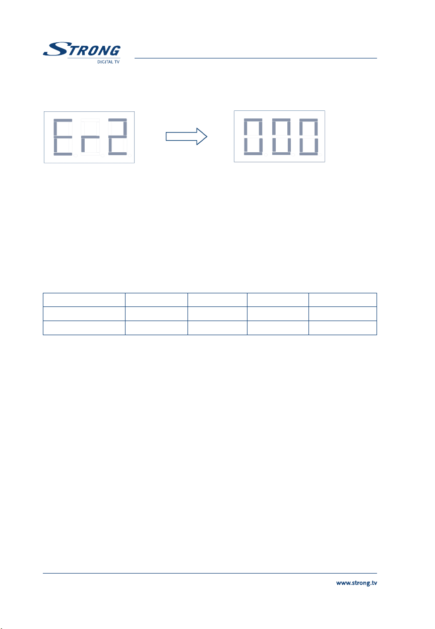
If reset has been successfully completed, it will show “ æ æ æ ” on the LED. After 2
seconds, it shows 000. (count number 1000).
After 2 Seconds
7.0 FOR DISEQC 1.2 RECEIVER
The denomination of some commands might be different, but similar. Please refer to the manual of
the Receiver.
Set the Software High / Low Limits:
After sending the commands from the DiSEqC 1.2 receiver, the Display of the positioner will show as below:
Low Limit High Limit
Low Limit High Limit
North Hemisphere
South Hemisphere
Cancel the Software High / Low Limits:
After sending the command from the DiSEqC 1.2 receiver, the Display of the positioner will show “LoF”.
East Limit West Limit
West Limit
East Limit
Page 10

PART 1 • English
9
English
Store the Satellite Positions:
1. Drive the Actuator East / West until the picture on the TV screen is clear.
2. Choose a sat. no. 1 ~60 and then send
3. The Display will show
Repeat Step 1 to 3 to set up all the satellites you prefer.
Recall a Satellite Position:
Change the satellite no. from the receiver, the positioner will drive the actuator to the intended position.
However, if the position has not been stored yet, the positioner will ignore the command.
Note: If the Channels and Satellites are well preset on the receiver, it will drive the actuator to the right
position while user changes the Channels. After arriving the right position, the Display will
show the Satellite no. as “P01” ~ ”P60”
Re-calculate (Adjust Shift) Function:
1. Recall one Satellite position stored in the positioner. The Display will show “PXX” (for
example “P03”) for 1 second and then the motor will start moving.
2. After the motor moves, drive the actuator East /West until the picture on the TV for this
Satellite is clear for “P03”.
3. Send Shift command (or re-calculate) from the DiSEqC 1.2 receiver.
4. After setting successfully, the Display will show ”PXX” again (for example “P03”). The
position PXX is shift to a new position.
Notice: If step 1. is skipped, the new antenna position will be shifted to P01. If P01 has not been stored
yet. The positioner will show “nuL” and no action
Sat Angle
0 10 °E 20 °E 30 °E 408E
“C01~C60” then show “P01~P60”.
Store command from the receiver.
.
.
Sat Angle
0 10 °E 20 °E 30 °E 408E
Satellite No. P01 P02 P03 Satellite No. P01 P02 P03
Go to the mechanical Position 0 (Operate by Receiver only):
1. Before using this function, please make sure the mechanical limit switches of the
actuator or H-H mount are well adjusted in order to avoid any damage or injury.
2. Send
“reset” or “Goto 0” command from the receiver. The positioner will drive the
motor toward East. If the motor goes to the wrong direction, just reverse the 2 wires
connecting currently to M1 & M2 on the positioner. The position index on the LED
display will be decreased until the motor stops due to the mechanical limit switch, then
Page 11
PART 1 • English
10
the Display will show “Er2” first then “000” which indicates the mechanical 0 position of
the Actuator.
Restore Factory Default (Reset):
This function will clear all data in the Positioner, includes High/Low Limits, Satellite Positions, …, etc.
Unplug from the AC outlet. Press the Power button on the top of the positioner and re-plug to the AC
outlet. Keep pressing the Power button for 3 seconds. The Display will show 10, 9 … 1, then reset the
system. To stop the Reset process, unplug from the AC outlet before counting to 1.
For DiSEqC 1.0 Receiver
1. For DiSEqC 1.0 Receivers, they can control up to 4 positions.
Position 1 2 3 4
LNB 1 2 3 4
LNB A B C D
The table is for your reference only. The operation might be different for different
receivers. For example, some receivers call position 1 ~ 4 as LNB1, 2, 3, 4 or DiSEqC A,
B, C, D. Please refer to the manual of your receivers.
2. In order to avoid confusion, the positioner will ignore the DiSEqC 1.0 commands after
receive the DiSEqC 1.2 commands. It can recognize the DiSEqC 1.0 commands again
after unplug from AC for more than 5 seconds.
3. The optional Remote Control is not necessary for DiSEqC 1.0 receivers. However, the
optional Remote Control is strongly recommended for the following reasons: 1) Easier
Operation. 2) More positions (from 4 to 60).
The following is the operation without remote control. If you have the optional remote control, please
refer to chapter For any Receiver
Store the Satellite Positions: Operate via the 3 Manual buttons
1. Drive the Actuator East / West via the manual East / West until the picture on the TV
screen is clear.
2. Press the
3. Press
4. Press Store button for confirmation within 3 seconds, the LED will show
Power / Store button for 5 seconds, the LED will show “C01”.
Up / Down buttons to choose the sat. no. you want to store: C01 ~ C60.
P01 ~ P60.
Page 12

PART 1 • English
11
English
Repeat Step 1 to 3 to set up all the satellites you prefer. However, for DiSEqC 1.0
receivers, only P01 ~ P04 can be used.
Manual Buttons
East (West)
/ Down
Recall a Satellite Position:
Change the DiSEqC 1.0 setting of the channels. The positioner will drive the dish to the right Satellites
while you change the channel. The Display will show “P01” ~ “P04”
Restore Factory Default (Reset):
This function will clear all data in the Positioner, includes High/Low Limits, Satellite Positions, …, etc.
Unplug from the AC outlet. Press the Power button on the top of the positioner and re-plug to the AC
outlet. Keep pressing the Power button for 3 seconds. The Display will show 10, 9 … 1, then reset the
system. To stop the Reset process, unplug from the AC outlet before counting to 1
West
/ UP
(East)
Power /
Store
.
8.0 TROUBLESHOOTING
Symptoms Check points
Can’t work with DiSEqC 1.0
Receiver
Can’t move to count less than 0
or more than 999.
The Stored Positions are not
correct.
The LED shows |- or -|, and
can’t move more.
1. Make sure position no.1 to 4 are stored.
2. After receive DiSEqC 1.2 commands, the DiSEqC 1.0 commands
will be ignored. Please operate the positioner by DiSEqC 1.2 receiver,
which is much better for motorization system.
The total position index of this Positioner is 2000 (0~1999),
which is enough for most of the application.
Use “Goto Position 0” Function to solve
1. Try to use the “*Re-calculate(Adjust Shift) function” to
correct the position first.
2. If it happens again and again, please replace the Reed
Sensor to check if the Sensor is stable
The symbols mean Electrical Limits, which have been set. If
you want to cancel this setting, use the “Limit Off Function”
from the receiver. And set the software limit again.
Page 13

PART 1 • English
12
Symptoms Check points
Er1 Message
(Over Current)
Or System Shut-down
n Make sure there is no short-circuit of the wire connection.
n Check if the Antenna is blocked by anything.
n Make sure the Motor works well. Some times a malfunction
Motor can cause higher current.
n Maybe the Antenna is too heavy. Please try to use our high-
power version.
Er2 Message (No Pulses) n Re-check the wire connection.
n Make sure the actuator is not stopped by Mechanical Limit.
n Check if the Reed Switch Sensor is broken.
n Check if the Motor is broken.
Er3 / Er4 Message
n Reset the positioner
(Internal Error)
Only the LED lights on and the
Positioner doesn’t work.
(No response)
n Unplug the AC Power Cord from the AC outlet. Wait for
more than 10 seconds then re-plug.
n This problem might be caused by the unstable AC power. In
order to protect the stored data, the Positioner will lock itself
under this situation. A voltage regulator might help.
Turn-Off Automatically
Can’t be Turned-off by optional
Remote Control or manual
The Display will be turned-off while LNB power is off.
If the LNB power of receiver is switched-on, the positioner
can’t be turned-off.
Power button.
Page 14

PART 1 • English
13
English
9.0 QUICK TABLE FOR OPTIONAL REMOTE CONTROL
Page 15
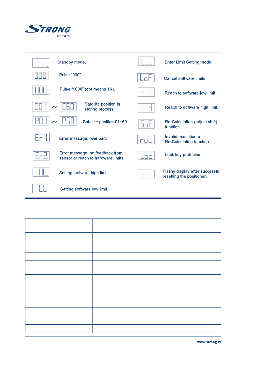
9.0 DISPLAY DESCRIPTION
PART 1 • English
10.0 SPECIFICACTION
Input Voltage 220 - 240 V AC 50Hz (110 V A C 60Hz Available)
Output Voltage 13 / 18 V DC (F Type / According to the Input)
Maximum Current 2.2A / 3.5A (High Power Version)
Power Consumption.
Position Memories 60 / 4
Protocol DiSEqC 1.2 / 1.0
Remote Control
Operating Temperature
Storage Temperature
Dimensions (W x H x D) 230 x 70 x 158 mm3 (Net) / 270 x 76 x 190 mm3 (Gross)
Weight.
14
13 / 18 V DC (F Type via Coaxial Cable)
36 V DC (via Motor Cable).
5 V DC (Optional for Optical Sensor)
Standby: 5W
Max.: 70W / 100W (High Power Version)
IR (Optional)
5 °C to 40 °C (41 °F to 104 °F)
-20 °C to 60 °C (-4 °F to 140 °F)
1.2 Kg(Net) / 1.3Kg(Gross) (+0.3Kg for High Power version)
 Loading...