

Page 1

User Manual
Digital Terrestrial Receiver SRT 5005/5010/5015
Page 2

1.0 Safety Instructions 3
2.0 Features & Accessories 4
3.0 Safety Precautions 5
4.0 Storage 5
5.0 Equipment Set-up 5
6.0 Connection 6
6.1 Connecting to Terrestrial Antenna 6
6.2 Connecting to TV & VCR 6
6.3 Connecting to Digital Audio Amplifier 7
6.4 Connecting to PC 7
7.0 Your Receiver 7
7.1 Front Panel 7
7.2 Rear Panel 8
7.3 Remote Control Unit 9
8.0 First Time Installation 10
9.0 Main Menu 12
9.1 Channel Organiser 12
9.2 Channel Search 14
9.3 Installation 27
9.4 Timer 28
9.5 Game 29
10.0 Other operations 31
10.1 Mosaic 31
10.2 EPG function 32
10.3 Teletext function 34
10.4 Information 35
A.1 Trouble Shooting 36
A.2 Specifications 38
A.3 Glossary of terms 40
2
Page 3

PART 1 English
1.0 Safety Instructions
DO NOT INSTALL YOUR RECEIVER:
In a closed or poorly ventilated cabinet;
Directly on top of or under any another equipment;
On a surface which might obstruct the ventilation slots.
DO NOT EXPOSE THE RECEIVER OR ITS ACCESSORIES:
To direct sunlight or near any other equipment that generates heat;
To rain or intense moisture;
To any shock which may cause permanent damage to your receiver;
To any magnetic objects, such as loudspeakers, transformers, etc.;
To intense vibration;
Never open the cover. It is dangerous to touch the inside of the receiver due to high
voltage currents and possible electrical hazards. Your warranty will be void if the receiver
has been opened.
When the receiver is not used for a long period of time, you should unplug the power cord
from the wall socket.
Do not use a damaged power cord. It may cause a fire or an electrical shock.
Do not touch a power cord with wet hands. It may cause an electric shock.
Place the receiver in a well-ventilated environment.
When you are connecting the cables, be sure that the receiver is disconnected from
the mains supply voltage.
Do not use your receiver in a humid environment.
Make sure you read this user manual before installing your receiver.
HOW TO USE THIS MANUAL
This manual provides complete instructions for installing and using this receiver.
The following symbols will serve as follow.
Warning Indicates warning information.
Tips Indicates any other additional important or helpful information.
MENU Represents a button on the remote control or the receiver. (Bold Character)
Move to Represents a menu item within a window. (Italic Character)
3
Page 4

2.0 Features & Accessories
SRT 5005/ 5010/ 5015 Digital Terrestrial Receiver:
Multi norm UHF modulator Ch 21-69 (Pal BG-I-DK-MN)
For all digital Free-To-Air TV and Radio programmes (with outdoor- or indoor terrestrial antenna)
DVB-T compliant, Digital UHF/ VHF Tuner with Loop-through function
Set-up support for first time installation
Quick and easy installation & user-friendly menu
Multi-lingual support on screen Menu: English, German, French, Italian, Spanish,
Hungarian, Czech
Excellent Audio- and Video quality
Automatic and manual channel scan options
Support of active antenna by 5V output
Support of channel numbering defined by broadcaster
1000 channels memory capacity
Favorite list for TV and Radio
Parental lock function for menu, selectable per channel
Electronic Programme Guide (EPG) for present/ following event information
and up to 7 days for on screen programme information
3 Operation Modes (Digital TV, Digital Radio, Favourite)
Support of Teletext (OSD & UHF modulator)
Multi-lingual subtitling and audio track support
2-SCART Connectors (TV, VCR)
Build-in RF modulator
S/PDIF output for connection with a digital audio amplifier
S-VHS Connector
3
Mosaic function: 9 TV Channels in overview
Automatic clock change: summer/winter time
Timer programmable via EPG
NTSC/PAL identification and converting automatically and manually
Separate power switch
Future proof: Over Air Download of the software updates
RS 232 port for updating control software and additional services
1
Subject of local broadcast condition
2
Only in models SRT 5010 and SRT 5015
3
Only in model SRT 5015
2
3
2
1
1
PART 1 English
1
Accessories:
User’s Manual
1 Remote control unit
2 x Batteries (AAA type)
Note: The batteries should not be recharged, disassembled, electrically short-circuited or be mixed
or used with other types of batteries.
4
Page 5

PART 1 English
3.0 Safety Precautions
To maintain your receiver’s optimum performance, you are advised to apply the following
safety precautions:
Read this manual carefully and make sure you fully understand the instructions given.
Refer all maintenance or servicing to suitably qualified personnel.
If you wish, you may clean your receiver with a soft lint-free cloth slightly made damp with a
mild soap solution, only after disconnecting from the mains voltage supply.
Do not use alcohol or ammonia based liquids to clean the receiver.
Do not open the receiver cover, as you will be exposed to a shock hazard.
Do not open the receiver cover this will void your warranty.
Do not place any objects on top of the receiver because this might prevent proper cooling
of the components inside.
Make sure no foreign objects fall through the ventilation slots because this could
cause fire or an electric shock.
Wait a few seconds after switching off the receiver before you move the receiver or
disconnect any equipment.
Please ensure that that the electrical power supply corresponds with the voltage on the
electrical identification plate at the back of the receiver.
It is a necessity that you only use an approved extension and compatible wiring that
is suitable for the electrical power consumption of the installed equipment.
If the receiver does not operate normally even after strictly following the instructions
in this user manual, it is recommended to consult your dealer.
4.0 Storage
Your receiver and its accessories are stored and delivered in a packaging, protective against electric
damage and moisture. When unpacking it, make sure that all the parts are included and keep
packaging away from children. When transporting the receiver from one place to another or if you are
returning it under warranty make sure you repack the receiver in its original packaging with its
accessories. Failing to comply with such packaging procedures could void your warranty.
5.0 Equipment Set-up
We recommend you to consult a professional installer to set up your equipment.
Otherwise, please follow the following these instructions carefully:
Refer to the user manual of your TV and your antenna.
Make sure that the SCART cable is in a good condition.
Make sure that the SCART cable connections are well shielded.
Make sure that the outdoor components of the antenna are in good condition.
5
Page 6
English
PART 1
6.0 Connection
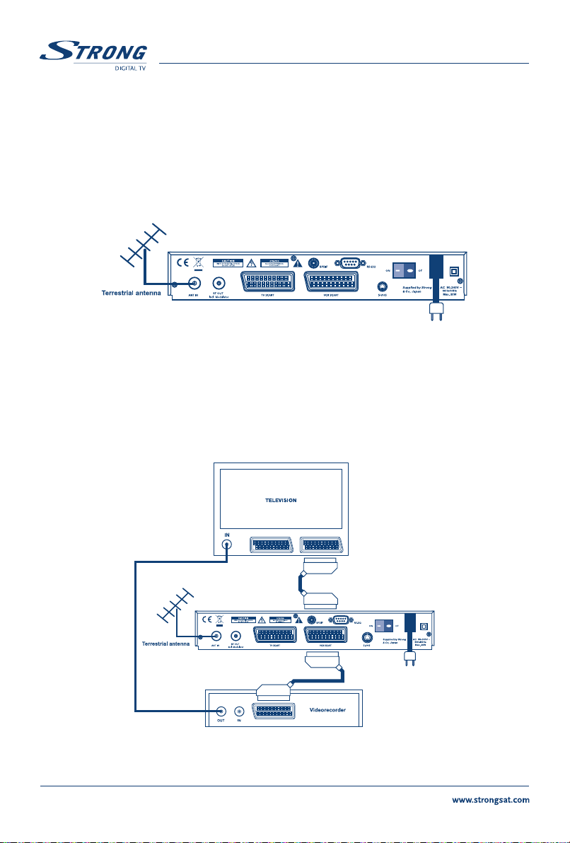
6.1 Connecting to Terrestrial Antenna
To receive the broadcast signal, the terrestrial antenna cable should be connected to the ANT IN
connector at the back of the receiver. (FIGURE 1)
FIGURE 1
6.2 Connecting to TV & VCR
The TV set should be connected with the receiver through a SCART cable. This terrestrial receiver may
also be operated together with a VCR using the loop through function. The loop-through function of
this terrestrial receiver is active when the receiver is powered off. As soon as the VCR is turned on,
its video and audio signals are looped through the terrestrial receiver. (FIGURE 2)
FIGURE 2
6
Page 7
English
PART 1
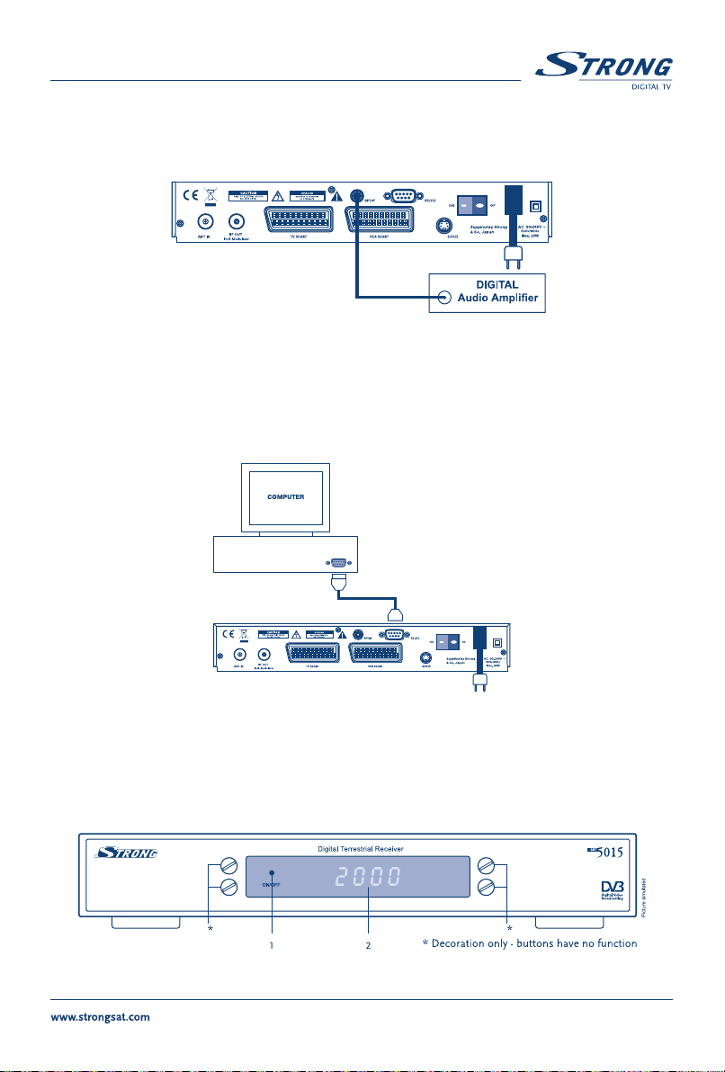
6.3 Connecting to Digital Audio Amplifier
The Digital Audio Amplifier is connected with the receiver from the S/PDIF connector. (FIGURE 3)
FIGURE 3
6.4 Connecting to PC
The RS-232 connector of the receiver helps to connect to the PC using a serial cable.This serial cable
can be used to connect your PC with your receiver, and allows you to download new versions of
software to your receiver. (FIGURE 4)
7.0 Your Receiver
7.1 Front Panel
FIGURE 4
FIGURE 5. Front Panel
7
Page 8
1. Mode indicator
The RED light indicates that the receiver is in STAND-BY mode.
The GREEN light indicates that the receiver is in AWAKE mode.
2. 4 Digits display
1
In STAND-BY mode indicates current time.
In AWAKE mode indicates current channel number.
1
Only in models SRT 5010 and SRT 5015
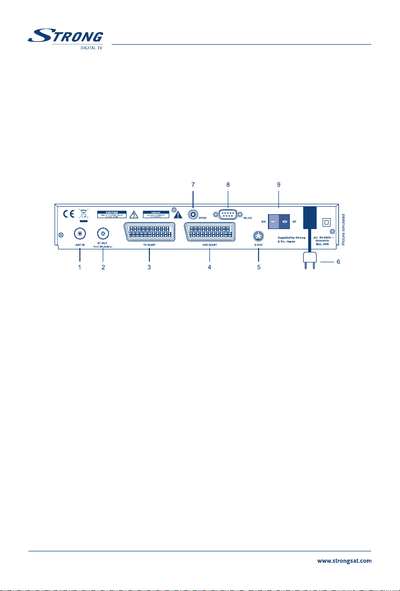
7.2 Rear Panel
PART 1
English
1. ANT IN
Use to connect a general Aerial Antenna for receiving broadcasting signal.
2. To TV
This gives you the possibility to connect a TV set in order to receive analogue channels or to
an extra receiver. (Includes modulator output in the model SRT 5015).
3. TV SCART Connector
4. VCR SCART Connector
Use this connector to connect your receiver with your TV set using a SCART cable.
1
Use this connector to connect your receiver to your video recorder using a scart cable. Your
video signal will now be looped through the receiver and your video recorder to your TV set.
5. S-VHS
2
Use this connector to connect your receiver to your TV and VCR using S-Video cable for better
picture quality.
6. Power Cord
Your receiver requires a current of 90 ~ 240 V AC (Auto-selectable), 50 ~ 60 Hz +/-5%.
Make sure to check the power specification before connecting your receiver to the wall outlet.
7. S/PDIF Digital audio output
Use this coaxial output to connect your receiver to the input of your digital audio amplifier.
8. RS 232 Serial Port
This serial port can be used to connect your PC with your receiver, and allows you to
download new versions of software to your receiver.
9. Power ON/OFF Switch
1
Only in models SRT 5010 and SRT 5015
2
Only in model SRT 5015
8
FIGURE 6. Real Panel
1
Page 9
PART 1 English
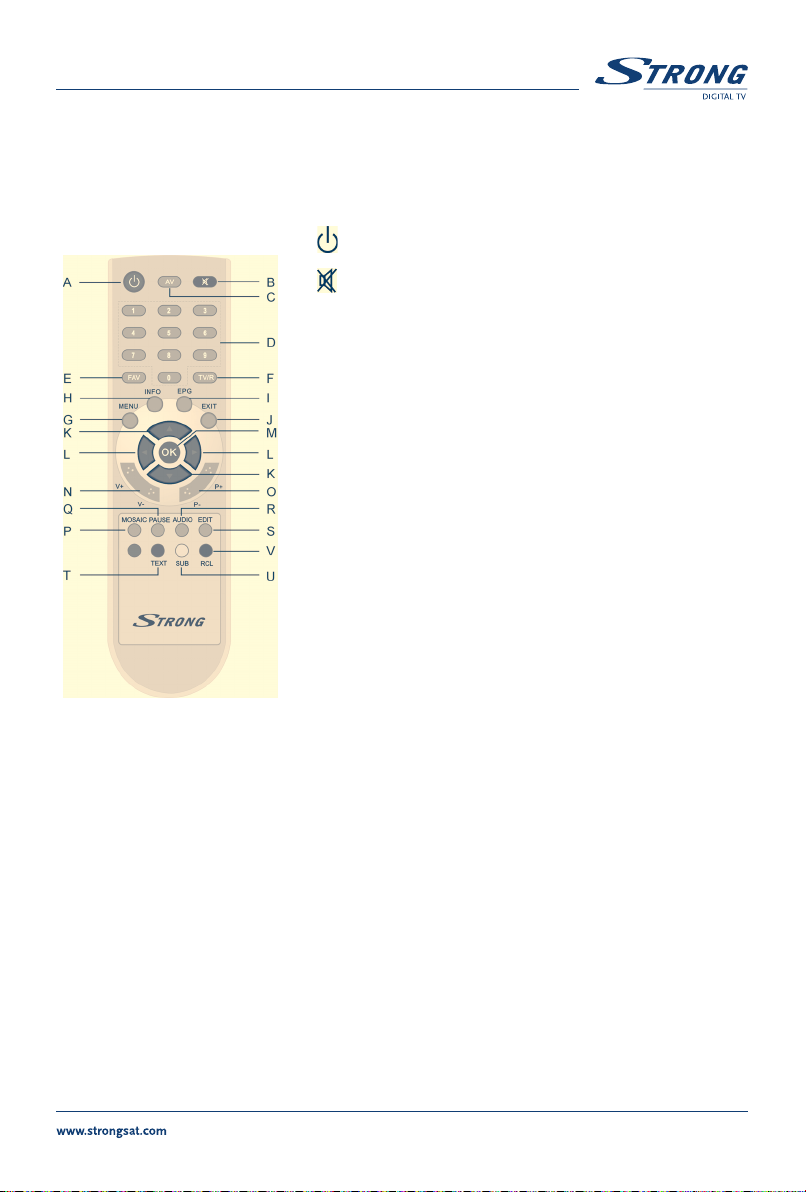
7.3 Remote Control Unit
All features of the set-top box can be controlled with the remote
control unit.
A.
B.
C. AV
D. 0~9
E. FAV
F. TV/R
G. MENU
H. INFO
I. EPG
J. EXIT
K.
FIGURE 7.
Remote Control Unit
N. V+ / V-
Use to increase or decrease the receiver volume level.
O. P+ /P-
Page up and down in menu list.
P. MOSAIC
Show pictures of 9 channels on the screen simultaneously
Q. PAUSE
Freeze/Resume picture.
R. AUDIO
Shows the list of available audio languages for the channel you are watching. In addition it
sets the current channel audio to stereo ((•)), left-mono ((• or right-mono •)).
L.
M. OK
Turns the receiver On/Standby.
Mutes audio output of the receiver.
Toggle between TV and AV mode.
Channel selection.
Toggle Favorite mode ON/OFF.
Toggle between TV or RADIO mode.
Shows the main menu and exits from any level of menu
to view mode.
Shows information of the current channel.
Shows the EPG (Electronic Program Guide) during
No-menu state only.
Exits from the menu or sub-menu and cancels
the progressing function if applicable.
Menu Off: Change the current program to the
previous/next program.
Menu On: Moves the cursor up/down.
Menu Off: Increases/decreases the volume level.
Menu On: Change the setting values in specific Menu item.
Activates the highlighted menu item. Displays a channel list
according to TV/Radio Mode
9
Page 10
PART 1
English
S. EDIT
Program edit.
T. TEXT
Shows current service’s Teletext on OSD (On Screen Display).
U. SUB
Show the list of subtitled languages the current channel supports.
V. RECALL
Switches back to previous channel.
8.0 First Time Installation
Make sure that your terrestrial receiver correctly connected to your Television and a terrestrial antenna
and that the signal quality is good enough. Confirm that the power plug of the receiver is plugged into
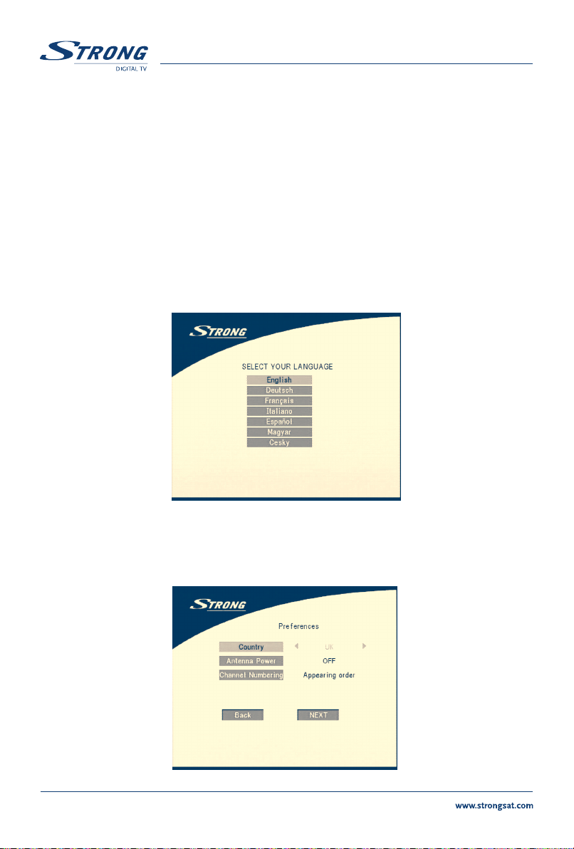
the wall outlet. Turn on the receiver. The following picture is shown at the first time.
SCREEN 1
It is recommended that you perform the first time installation following Installation Wizard step by step. This
will help you easily achieve system configuration and channel installation. If you are a professional installer
then you can skip the wizard by pressing
Press UP/DOWN to choose your language, press OK to confirm. The preference menu will appear as below.
10
EXIT button and set-up the channels using the Channel Search menu.
SCREEN 2
Page 11
PART 1 English
Please select your Country, Antenna Power mode and Channel numbering. Press UP/DOWN to select
the items, press
If you choose
OK to confirm those setting and enter the Adjust antenna menu (shown as SCREEN3).
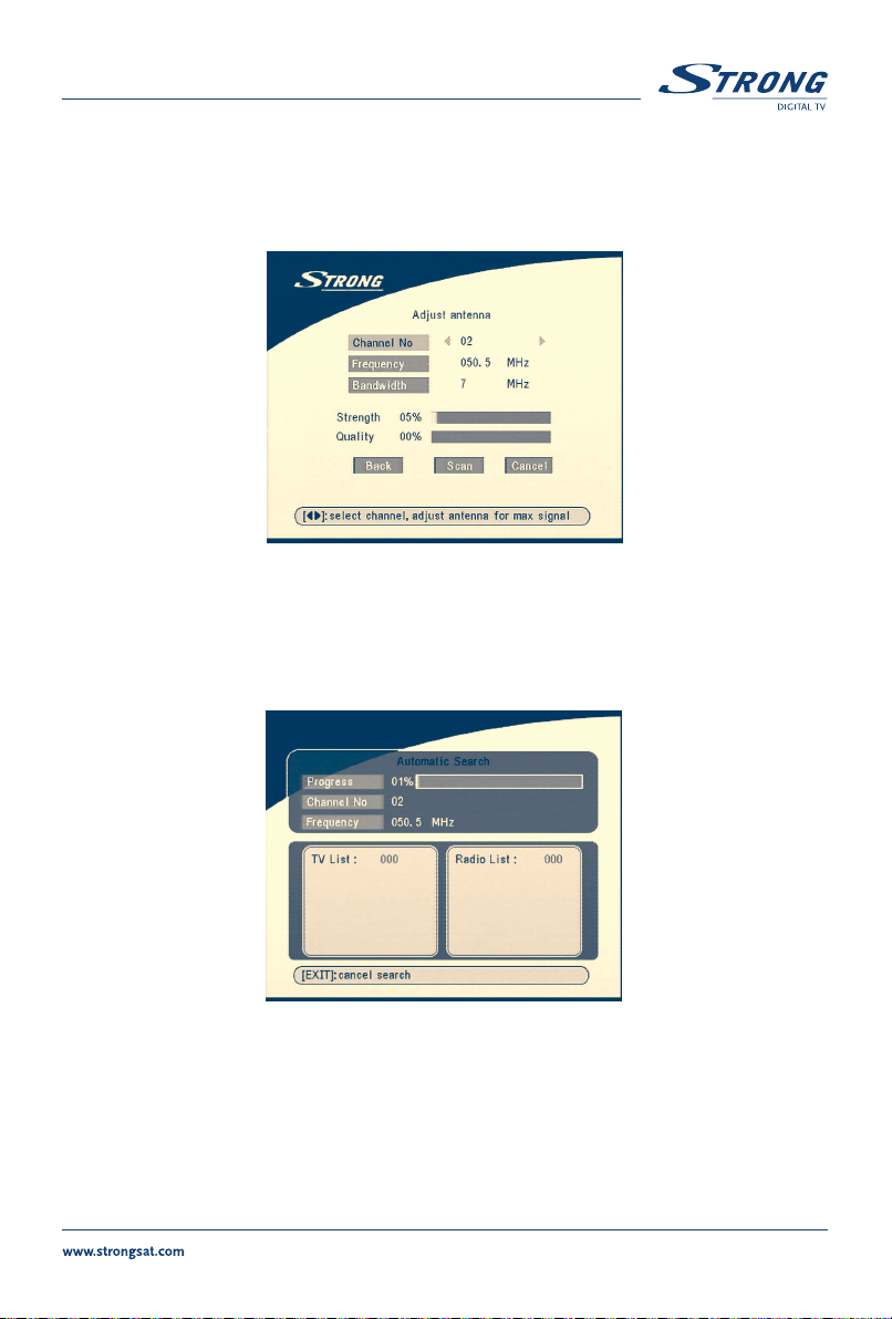
Press
Press LEFT/RIGHT to select Channel No, adjust your antenna direction and position (if necessary)
to get maximum levels of the signal level and quality indicators. You can check with your dealer on
which channels digital terrestrial broadcast is available at your location.
Move cursor to
RIGHT/LEFT to change the value of the item.
BACK, It will go back to SCREEN 1.
SCREEN 3
Scan, press OK to confirm, The Automatic Search screen will appear as below.
Completed search, receiver will save services information automatically and exit to normal play state.
SCREEN 4
11
Page 12
PART 1 English
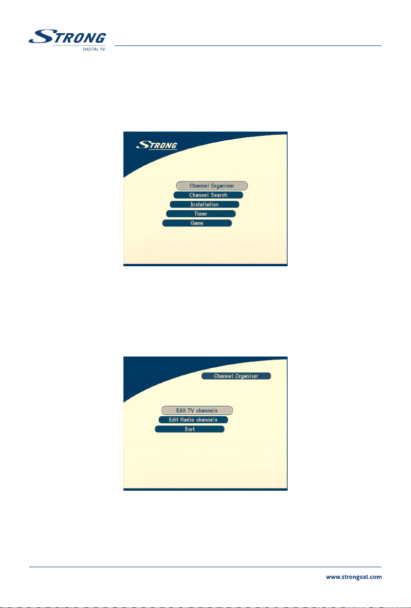
9.0 Main Menu
All the important settings and features of your receiver can be operated in Main Menu. The Main Menu
consists of five sub-menus such as
With Menu off, press
MENU key. The MAIN MENU screen will appear (SCREEN 5).
"Channel Organiser", "Channel Search", "Installation", "Timer", "Game".
SCREEN 5
9.1 Channel Organiser
In MAIN MENU screen, press UP/DOWN to move the cursor to Channel Organiser, and then press OK
to enter the Channel Organiser menu.
The Channel Organiser menu consists of three sub-menus, which are “Edit TV Channel”, “Edit Radio
Channel”
12
and “Sort”.
SCREEN 6
Page 13
PART 1 English
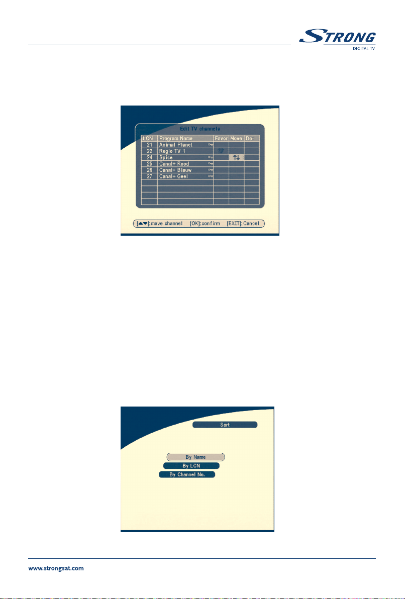
9.1.1 Edit TV channels
In this menu, you can set the favorite channels, change the order of channels and delete channels.
Press UP/DOWN keys to point focus of the menu to the channel of your selection.
LEFT/RIGHT keys to point focus of the menu to the column with the function, which you want to
Press
apply to the selected channel.
When the focus is on column
When the focus is on column “Move”, press the OK button to confirm selection of the channel, using UP/DOWN
buttons move channel to new location and press the OK button to confirm new location. Repeat this for every
channel that you want to move. When the focus is on column “
selected to be deleted from the list. To apply changes press the
“Favor”, press the OK button to add selected channel to the Favourite list.
SCREEN 7
Del”, press the OK button to mark the channel as
EXIT button and confirm channel deletion.
9.1.2 Edit Radio Channels
This menu is similar as to 9.1.1 “Edit TV Channels” description.
9.1.3 Sort
You can sort the order of the channel list by channel name, LCN (Logical Channel Number) or Channel Number.
SCREEN 8
13
Page 14

9.2 Channel Search
PART 1 English
There are 2 items in the channel Search menu:
1.
Automatic Search
2. Manual Search
SCREEN 9
9.2.1 Automatic Search
Press OK over the Automatic Search. A warning message will appear.
Press LEFT/RIGHT to move the cursor to OK and press OK to continue.
A message will appear.
14
“Please Press LEFT/RIGHT to choose whether to erase your previous channel list”.
SCREEN 10
Page 15

PART 1
English
SCREEN 11
Then it will search for the programs automatically. If you want to cancel the channel search you may press
the EXIT button.
SCREEN 12
On completing the search, the receiver will save the services information automatically and exit
to normal play state.
SCREEN 13
15
Page 16

PART 1 English
9.2.2 Manual Search
Press OK over the Manual Search, the Manual Search Screen will appear.
SCREEN 14
Press LEFT/RIGHT to choose channel No. or press numerical buttons to input channel No.
Or
Press
UP/DOWN to move focus to Frequency item and enter frequency value using numerical buttons.
UP/DOWN to move focus to Bandwidth and choose bandwidth using LEFT/RIGHT buttons.
Press
Check indicators of the signal level and quality to make sure that values are entered correctly.
UP/DOWN to move cursor to Search and press OK to search current channel.
Press
If no service is installed, there will be a warning. Press any key to return.
SCREEN 15
Tips
Different countries have different VHF/UHF frequencies plan. It is important
to choose the proper region.
9.3 Installation
9.3.1 System Setting
In this menu, you can configure the systems such as language, TV Settings, Country, Channel
Numbering, Antenna Power, Time Setting, and Factory Default.
16
Page 17

PART 1
English
SCREEN 16
9.3.1.1 Language
You can change the language of the OSD and Audio.
Press
UP/DOWN to select the OSD language or Audio language. Press OK/RIGHT to enter the
language list and Press
UP/DOWN to select the language. Press OK to confirm.
SCREEN 17
17
Page 18

9.3.1.2 TV settings
You can set TV Standard, TV format, Video output and Modulator Settings.
SCREEN 18
TV Standard
The TV Standard Screen will appear as follows:
PART 1 English
Press OK/RIGHT to select PAL or NTSC, press OK to confirm. If you don’t know which standard your
TV has, please select AUTO.
18
SCREEN 19
Page 19

PART 1 English
TV format
The TV format Screen will appear as follows:
SCREEN 20
Press OK/RIGHT to select 4:3 or 16:9, press OK to confirm.
Video output
The Video output Screen will appear as follows:
Press OK/RIGHT to select CVBS/RGB or S-Video, press OK to confirm.
SCREEN 21
Warning! If RGB is selected > S-VHS output is switched OFF totally.
Note: S-Video option available in model SRT 5015 only.
19
Page 20

PART 1 English
Modulator Settings (only for model SRT 5015)
The Modulator Settings Screen will appear as follows:
SCREEN 22
Press UP/DOWN to select RF Audio Mode or RF Channel. Use LEFT/RIGHT to set RF Audio Mode and
RF Channel. Press OK to confirm.
9.3.1.3 Country
SCREEN 23
Press OK/RIGHT to select your country in the country list, press OK to confirm. If your country is not
in the list then select Other. It will apply the most common frequency plan for European countries.
20
Page 21

PART 1
English
9.3.1.4 Channel Numbering
Here you can set the channel list by different number format, Appearing order or Operator defined.
SCREEN 24
9.3.1.5 Antenna Power
Press OK/RIGHT to select turn OFF or ON the antenna power, press OK to confirm. Before set
Antenna Power to ON: make sure that your antenna is ACTIVE, requires power 5V DC and it’s power
consumption is not more then 100 mA.
SCREEN 25
21
Page 22

PART 1
English
9.3.1.6 Time settings
If a broadcaster provides GMT, you can set the time using GMT, or set your own time by yourself.
If the GMT usage is ON then the Current time is set automatically or you can set the time zone.
If your broadcaster provides the correct time offset then your receiver will change from summertime to
wintertime automatically.
If you set GMT Usage to OFF, Set Data and Set Time item are displayed.
To set the time value manually, move the cursor to the time item and use the numeric buttons on the
remote control.
SCREEN 26
9.3.1.7 Factory Default
Select Factory default and press OK. Select YES and press OK key, the receiver will return to its factory
default state, and all user data will be deleted.
SCREEN 27
22
Page 23

English
PART 1
9.3.2 Personal Style
In this menu, we can set the menu colour, transparency level, border pattern and entry animation.
Press UP/DOWN to select the item, and Press LEFT/RIGHT to set the value, press OK to confirm.
SCREEN 28
9.3.3 Parental Control
In this menu, you can set channel lock status (ON or OFF), the menu lock status, parental setting
and change the PIN code (shown as SCREEN 29).
The default PIN code is 0000.
SCREEN 29
23
Page 24

English
PART 1
9.3.3.1 Channel Lock
Set the system channel lock to ON or OFF. If the channel locks on, user has to enter the parental PIN
code correctly before watch the locked program.
SCREEN 30
9.3.3.2 Menu Lock
Press OK to select whether you need the lock or not for the Menu, YES or NO, press OK to confirm.
If the menu lock is on, then for some operations such as search program and set factory default, you
need to enter your PIN.
SCREEN 31
24
Page 25

English
PART 1
9.3.3.3 Parental setting
Set some programs to lock status. If a channel is locked, the user has to enter the parental PIN code
correctly before watching the locked channel.
Use UP/DOWN keys to select channel which you want to lock.
OK button to lock channel.
Press
SCREEN 32
9.3.3.4 Change PIN
Modifying the password. You must enter the 4 digit password and then confirm it again; the system
password will changed into the new password as shown on SCREEN 33.
SCREEN 33
25
Page 26

9.3.4 System Information
Display the software version information.
Press
OK/EXIT keys to return.
SCREEN 34
9.3.5 System Update
In this menu, you can select between “STB to STB” and “OAD”.
9.3.5.1 Update through STB to STB
PART 1 English
The System Update screen will appear.
When it is necessary to update the System, please follow these steps:
a) First power off both STBs, connect them with cross RS 232.
b) Then power on master STB (master is STB from which you will copy software) and keep
slave STB off. Navigate in the menu of master STB and select
c) When the status displays “detecting slave STB”, power on slave STB, after the master
STB detects the slave, the master starts transmission and burns.
d) While transmitting and burning, it is very important to avoid other operations such as
power off because this may cause destruction of the data in the FLASH memory and
the receiver will need to be repaired.
e) When update complete, please first power off both STBs, then disconnect the RS 232 line.
Tips The system updates just update the software and the programsdatabase are not be updated.
26
SCREEN 35
“System Update – STB to STB”.
Page 27

PART 1 English
9.3.5.2 Over Air Download (OAD)
Select this option in order to update your receiver with the latest software version.
The receiver will check availability of the software update on air and load the latest software, if available. You will be asked to confirm update. Do not switch power off and do not disconnect the receiver
from the aerial during update process.
Availability of the software update is subject of local broadcast condition and may not work in all
countries. Contact your vendor to find out more about this function.
9.3.5.3 Update through PC to STB
1. Connect Computer to receiver (receiver must be power off) with a 9-pin cross cable
(two females)
2. The computer follows below steps:
Start-> Programs-> Accessories-> Communications-> Hyper terminal
Then choose
setting as follows:
*Note: Incorrect operation may cause unrepairable damage to the receiver.
“COM1” or “COM2” according to which port you are using in the computer and port
Bits per Second: 115200
Data bits: 8
Parity: None
Stop bits: 1
Flow Control: None
3. In Hyper Terminal menu select
with new software (
“1K Xmodem”. Finally press ok and a download menu will appear in the computer screen.
Power on the receiver, then the download progress will start.
4. After about 2.5 minutes, the message
Terminal window, which means the download has completed successfully.
5. Power off the receiver and then unplug out the RS 232 interface.
1. DO NOT POWER OFF THE RECEIVER DURING THE PROCESS OF DOWNLOAD.
2. DO NOT PLUG IN OR UNPLUG THE RS232 INTERFACE WHEN RECEIVER IS POWERED ON.
*.UPD) you want to download and choose the protocol
“Transfer” item and then press “Send file” item. Select the file
“OK, Reset” will appear on the computer on Hyper
27
Page 28

English
PART 1
9.4 Timer
You can set the timer to make the receiver perform designated actions including timer based wake
up/sleep the set-top-box.
SCREEN 36
Use UP/DOWN buttons to select timer. Press LEFT/RIGHT key to activate/inactivate current timer. Press
OK button to enter selected timer settings.
Action: You can select the following functions:
Cycle: You can set the cycle of the action designated in the timer mode (one time,Daily
Start Date: You can set the starting date of the timer action.
Start Time: You can set the starting time of the timer action.
End Time: You can set the ending time of the channel view when the Timer mode is on
Channel Type: Select between TV and Radio.
Channel Name: Press RIGHT button to display channel list and using navigation buttons select
“Power On”: The receiver powers on at the designated date and time.
“Time interval”: The receiver switches on at the designated date and time, displays
the channel and then switches off at the designated date and
time (The value set at the end time).
“Power Off”: The receiver powers off at the designated date and time.
or Weekly).
Time Interval.
channel to be shown when the receiver will power on by timer.
SCREEN 37
28
Page 29

PART 1 English
9.5 Game
The receiver has three games (Mine, Tetris and Gomoku) and calendar. In this menu user can select
any game item and press
into the game menu directly.
OK to play the game. Or you can press GAME key on normal play state
SCREEN 38
9.5.1 Mine
Key function:
UP/ DOWN/ LEFT/ RIGHT button:
MENU button: Make Mark to the mine.
SCREEN 39
Move the cursor.
29
Page 30

9.5.2 Tetris
PART 1 English
Key function:
LEFT/RIGHT:
DOWN: drop block.
UP: Rotate block.
9.5.3 Gomoku
Key function:
UP/DOWN/LEFT/RIGHT:
OK: Place the gobang.
SCREEN 40
Move block to left or right direction.
SCREEN 41
Move the cursor.
30
Page 31

PART 1 English
9.5.4 Calendar
UP/DOWN: +/- months.
LEFT/RIGHT: +/- years the range from 1900 to 2100.
10.0 Other operations
SCREEN 42
10.1 Mosaic
In no-menu state, press MOSAIC button. Screen will be divided into nine pictures screen:
Press UP/DOWN/LEFT/RIGHT keys to choose one of current programs.
Press P+/P- keys to view another nine programs.
OK key to return to normal play state and play the selected program.
Press
EXIT key to return normal play state and change nothing.
Press
SCREEN 43
31
Page 32

10.2 EPG function
In no-menu state, press EPG, EPG Menu will appear:
PART 1 English
Press UP/DOWN to choose channel.
Press RIGHT into EPG schedules of current channel.
In EPG schedules menu:
Press UP/DOWN keys to choose schedule items.
Press P+/P- into next/previous day schedules.
LEFT/EXIT return to EPG Menu.
Press
OK/RIGHT to show the details of this item.
Press
SCREEN 44
SCREEN 45
32
Page 33

PART 1
English
In EPG schedule details:
SCREEN 46
Press P+/P- into next/previous page.
Press
LEFT/EXIT return to EPG schedule Menu.
You can set up the event timer by pressing OK in EPG schedule details or EPG schedule screen.
To set up an event timer:
1.Press UP/DOWN to move the cursor to the event for which you want to add a timer.
2.Press OK to add a timer.
SCREEN 47 shows you current event timer information based on the event you have chosen. You can
also modify each value. To save the settings, press
OK. To quit event timer setup, press EXIT.
SCREEN 47
33
Page 34

10.3 Teletext function
In no-menu state, press TEXT.
SCREEN 48
In TEXT on OSD:
Press UP/DOWN to add/ subtract displayed page number
Press NUMERIC keys to input page directly.
If the current program has no Teletext, the screen will appear as below:
PART 1
English
SCREEN 49
34
Page 35

PART 1
English
10.4 Information
The following screen will be shown when you press INFO key twice times in the no-menu state.
The screen will show you current channel information.
SCREEN 50
35
Page 36

PART 1 English
A.1 Trouble Shooting
Before requesting servicing for your receiver, please check the table below for a possible cause of the
problem you are experiencing. Some simple checks or a minor adjustment on your behalf may
eliminate the problem and restore proper operation. The most common problems that arise are related
to cable connections. Make sure that your decoder is properly connected. To ensure that all the cables
are in their place, disconnect and connect them again. If none of the remedies indicated in the table
below solve the problem, consult your vendor.
Installation issues
Symptom
Your decoder does not find
channels
Symptom
No picture if receiver is
connected only by
S-VHS Cable
Symptom
No sound only picture
General issues
Symptom
The standby indicator on the
receiver’s front panel does not
light up
Remedy
If you are using a directional aerial, make sure it is directed towards a
digital TV transmitter and positioned correctly.
Make sure that it is possible to receive digital terrestrial signal in your
area.
It is advisable to use a standard outdoor aerial, which normally have
better characteristics than the indoor one.
Check the cable from the aerial.
If you cannot resolve the problem easily you may need to have your
aerial and installation tested by a professional.
Remedy
If you are using only the S-VHS output, make sure that in System
Setting S-Video is selected. If RGB is selected is S-VIDEO out disabled.
Remedy
You are using only the S-VHS output. This support only Video no
Audio. Connect receiver also with the Digital output (S/PDIF) to an
digital amplifier.
Remedy
Check that power is available at the wall socket. Check if the SCART
cable and antenna cable are correctly connected and the receiver is
switched on. Disconnect these cables, and then reconnect them to
ensure they are in place.
36
Page 37

PART 1 English
The standby indicator on the
receiver’s front panel is red
Your remote control fails to
operate your receiver
No program broadcast has
been recorded on your VCR
Electronic Program Guide
(EPG) issues
Symptom
The EPG is empty
Audio & video issues
Symptom
The picture on your TV screen
changes color. This may
happen after a power-cut or
after your receiver has been
disconnected from the power
source.
Your receiver is in standby, press the power button on your
remote control.
Check the batteries in your remote control. Make sure your receiver is in
the operate mode. Make sure that you are pointing your remote control
at the receiver’s front panel.
Make sure that there is no direct sunlight from behind your receiver.
There may be a temporary transmission error, or your receiverr has lost
some of its software settings. Switch off your receiver at the power source
and switch it on again after a few seconds.
Check the connection between the receiver and VCR. Please make sure
your VCR is set properly.
Remedy
The selected program does not support EPG. The local time is incorrect.
Set the correct local time.
Remedy
Your receiver has lost some of its software settings. Switch your receiver
off and switch it on again after a few seconds. If the problem persists,
contact your vendor.
Blocks appear in the picture
on the screen.
The signal is too weak or defective due to e.g. bad weather conditions.
Try to adjust your aerial position or wait for the signal to be re-established.
37
Page 38

A.2 Specifications
1. Tuner & Channel for Terrestrial
Type IEC 169-2 Female
Frequency Range VHF and UHF
Bandwidth 8 MHz or 7 MHz or 6 MHz
Input impedance 75 ohm unbalanced
Signal Level -82 ~ -20 dBm
2. Demodulation
Waveform COFDM
Constellation 16 QAM, 64 QAM
Transmission mode 2K, 8K
Guard Interval 1/4, 1/8, 1/16, 1/32
Code Rate 1/2, 2/3, 3/4, 5/6, 7/8
3. System & Memory
Flash Memory 16 Mbits
SDRAM 64 Mbits
Channel Memory Up to 1000 channels
Remote Controller 36 Keys, IR Remote Control
4. MPEG Transport Stream & A/V Decoding
PART 1 English
Transport Stream MPEG-2 ISO/ IEC 13818
Profile Level ISO/IEC 13818-2 MPEG-2 MP@ML
Input Rate Max. 60 Mbits/s
Aspect Ratio 4:3, 16:9
Frame Rate PAL: 25 Hz; NTSC: 30 Hz
Video Resolution 720 x 576 (PAL), 720 x 480 (NTSC)
Teletext DVB-TXT ETSI/EN 300 472
Audio Decoding MPEG/MusiCam Layer 1 & 2
Frequency Response 20 Hz ~ 20 kHz, < +/-2 dB
60 Hz ~ 18 kHz < +/-0.5 dB
Sampling Rate 32, 44.1, 48 kHz
5. A/V & Data In/Out
TV Scart Output RGB, CVBS, Audio L/R Output with Volume Control
VCR Scart Input/Output
S/PDIF output
RF Modulator
1
2
1
Input: CVBS, Audio L/R
Output: CVBS, Audio L/R Output with Volume Control
Digital audio output, coaxial
UHF output channels CH21-69 selectable via menu
PAL B/G, D/K, M/N or I selectable
Data Interface RS 232, Bit Rate: 115200 baud
S-VHS output
2
Connector: 9-Pin D-Sub Male type
High video quality output.
38
Page 39

PART 1
English
6. Power Supply
Input Voltage 90 – 240 V AC, 50/60 Hz +/-5 %
Power Consumption Max. 20 W
Stand-by Power <= 8 W
7. Physical Specification
Size (W x H x D) 260 x 40 x 140 mm
Weight 1.2 kg
8. Environmental Conditions
Operating Temperature 0 ~ 40°C
Storage Temperature -30° C ~ 80°C
Operating Humidity Range 10 ~ 85 % RH, Non-condensing
Storage Humidity Range 5 ~ 90 % RH, Non-condensing
1
Available in models SRT 5010 and SRT 5015
2
Available in model SRT 5015
39
Page 40

A.3 Glossary of terms
PART 1 English
DVB-T Digital Video Broadcasting Terrestrial - Digital TV via antenna (same as DTT- Digital
EPG Electronic program guides that are transmitted by some broadcasters to display
MPEG The Moving Picture Experts Group is founded by the ISO. MPEG is a standard
PAL Referring to the Phase Alternate Line colour system adopted by European broadcasters.
Parental lock This function gives you the possibility to ‘lock’ several functions of the receiver to
PID The transmitted packages have identifiers (PID) that tells the receiver what to do with
PIN CODE Personal Identification Number. A four-digit code that is used for locking/unlocking,
RS 232 Serial data port.
S-VIDEO Specially Video output without Audio, which transport Colors and Screen information
Terrestrial Television).
information guide about a program content.
method fordigital transmission of video and audio. Network A network which is also
known as a bouquet is a set of channels that is offered by a single broadcaster.
prevent unauthorized users such as children to view channels that are not suitable for
them. A PIN code is required to use of the parental lock.
the received information. Receivers normally use four types of PID, these are V-PID
(video PID), A-PID (audio PID), P-PID (Program PID) and data PID (EPG information).
e.g. with the parental control feature.
separare to the TV-set. For a better picture quality.
40
Page 41

Environmental Issues
Environmental Issues
Strong is committed to reducing the impact of its products on the environment.
To maximise the benefits of our design enhancements, your co-operation is required.
Electronic product recycling
Do not dispose of this product with your
domestic rubbish
At the end of its useful life, this product
contains materials which when processed
correctly can be recovered and recycled.
By participating in the responsible recycling
of this product you will be reducing the
requirement for new raw materials and
reducing the amount of material that
would otherwise end up in landfill.
When you purchase a new, similar product
your retailer may offer to take this old one
off you. Alternatively, you can take it to
your local recycling centre. Your retailer or
local municipal authority will advise you
of the collection facilities available for
waste electronically products in your area.
User of this service will be free to you.
Within the scope of the European legislation
on Waste Electrical and Electronic
Equipment (Directive 2002/96/EC valid
as of August 2005) STRONG provides a
recycling system free of charge for
consumers to returning products after end
of life. For more information about
STRONG’s environmental policy to you:
www.strongsat.com - select “About us”
and “Environmental Policy“ from
the submenu.
Packaging
When disposing of this product
packaging, please ensure that it is
recycled. Packaging material is to
be depolluted in waste separation.
Power Saving
To save power and money, please
put the product into standby mode
when not in use. We also recommend
disconnection from mains supply
when not in use for longer periods
of time.
Batteries
Do not dispose of the batteries
from your handset with your
domestic waste
Where they are available, participate
in your local municipal or retailer
collection schemes for spent
batteries. Batteries discarded in
landfill sites or incinerated increases
the chances of pollutants being
dispersed into the atmosphere.
Alternations reserved 9/2005
 Loading...