

Page 1
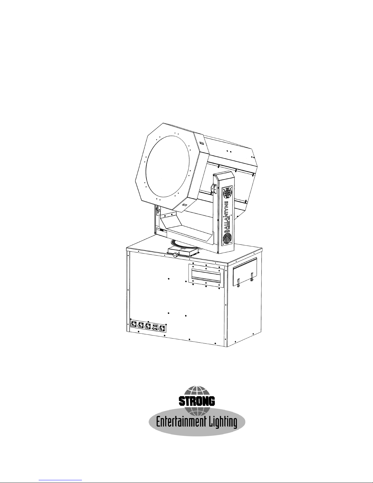
SEL10
Lamphead & Base Assembly
for Equipment Type MLS210
Rev. October 17, 2000
Operator’s Manual & Parts List
4350 McKinley Street • Omaha, Nebraska 68112 USA
a division of Ballantyne of Omaha, Inc.
Tel 402/453-4444 • Fax 402/453-7238
Page 2
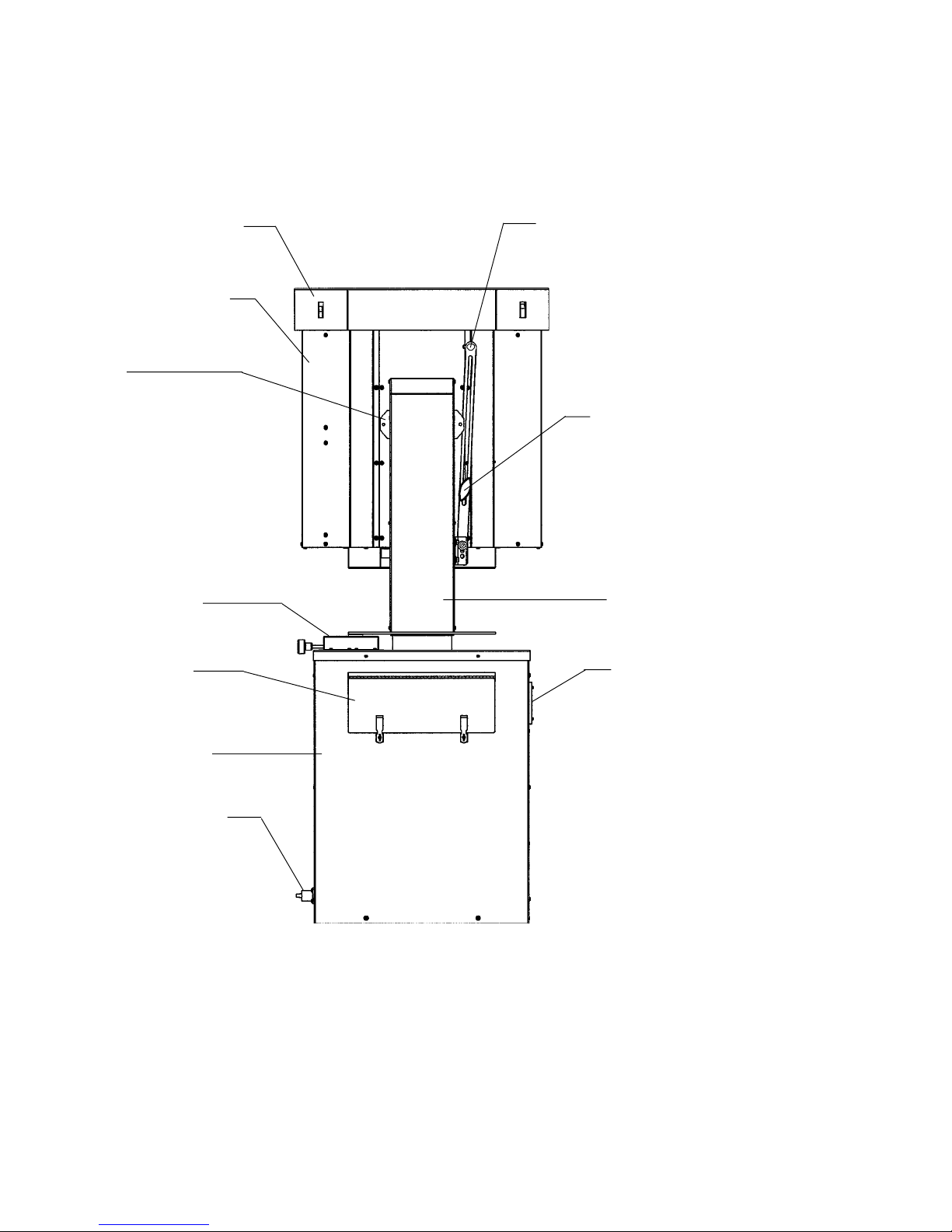
Front Cowl Assembly
Lamphead Housing
Hoisting Bracket
(1 of 4)
Locking Mechanism,
Horizontal Pan
This Bolt Installed for
SHIPPING ONL Y.
Remove Bolt after transporting Lamphead. Set Projection
Angle and secure tilt angle
using Clamping Knob.
Clamping Knob,
Projection Angle
Yoke Assembly
Cover Plate,
Control Panel
Base & Power
Supply Housing
Power Input Jacks
Ventilation Opening
(Do Not Obstruct)
SEL10 LAMPHEAD & BASE ASSEMBL Y
Secured for Transport
Page 3

PREFACE
The SEL10 is a 10,000 watt xenon searchlight mounted on a rotating base. The angle and
direction of light projection are independently adjustable through a 360° arc in either direction, and
lock manually in the desired position. The unit is mounted on a trailer and powered by a diesel enginegenerator unit.
Continuous high output performance is assured by means of a coated, 30 inch precision
electroformed, parabolic nickel reflector. The reflector is carefully positioned at the factory and requires no operator adjustment. The light source is a 10,000 watt xenon bulb which can operate in any
position (vertical to horizontal) and maintains a constant color temperature of 5600° Kelvin. A
squirrelcage blower is mounted in the lamphead to provide continuous forced-air cooling while the
bulb is in operation. The bulb is warranted for 500 hours.
Operator controls mounted to the instrument panel include a LAMP ON/OFF switch and a
FOCUS switch. An AC motor inside the lamphead moves the bulb inside the reflector to adjust focus.
An hour meter, located adjacent to the switches, records the elapsed time of xenon bulb operation.
Direct current for the xenon bulb is derived from two high reactance xenon power supplies
mounted in the base of the unit. All models are designed for 50/60 Hertz operation, and are available
in varying AC input types, depending upon the confuguration of the main power transformer. Check
the Equipment Data Plate to determine the exact AC requirement prior to installation.
Coarse and fine taps are easily set to regulate the DC currnt to the xenon lamphead. Some
models of these power supplies have the capability of overdriving the xenon bulb; carefully check the
power requirements specified by the bulb manufacturer and do not exceed the maximum current stated.
The two power supplies, wired in parallel, produce the high open circuit ( “no load”) voltage
required for bulb ignition, and, after ignition, the filtered low voltage current to sustain operation. The
bridge rectifiers utilize silicon diodes as the power conversion elements. The diodes are mounted to
oversize heat sinks to disperse the heat generated by normal operatrion. Internally wired squirrelcage
blowers provide additional forced-air cooling of each power supply. Thermal switches act as safety
interlocks to shut down the power supplies and protect the rectifier diodes in case temperatures reach
excessive levels.
INSTALLATION
Check the equipment Data Plate and make certain that the AC source conforms to the power
requirements of the main transformer. The AC service wiring should be installed by a licensed electrician in conformance to local codes. The unit must be connected to an adequate earth ground.
The AC line to the xenon power supply must include a marked line safety switch or other power
disconnect device adjacent to the unit and accessible to the operator. For operator safety, it is
necessary to turn off all power to the unit when adjusting or servicing the xenon power supply. This safety
switch or power disconnect should be tagged “OFF - UNIT UNDER REPAIR” when the power supply is
being serviced.
On trailer-mounted units, connect the (3) phase leads and the (1) ground lead from the generator unit to the color-coded power inlet jacks near the bottom of the base cabinet. Set generator output
to 208/230 V.AC, 60 Hz.
Observing all safety procedures, install a 10,000 watt xenon bulb into the lamphead. Check the
bulb manufacturer’s documentation to determine the recommended current range of the bulb. Most
10 kW xenon bulbs operate between 180 to 220 amperes DC at 45 to 55 volts DC. A new bulb is normally
first operated at “nominal” current, which is around 85% of the maximum level (190 A.). DO NOT, at any
time, exceed the maximum current level (220 A.) specified by the bulb manufacturer.
1
Page 4
INSTALLATION (continued)
Remove a side panel from the base assembly to gain access to the bridge rectifier of one of the
xenon power supplies. Use either the positive (red) or negative (black) lead at the top of the rectifier heat
sink as a connection point for the clamp-on ammeter. Voltage measurements can be taken at the hex
head screws connecting the red (+) and black (-) leads to their respective heat sinks.
safety precautions when taking voltage and current readings in a power “ON” condition.
Observe all due
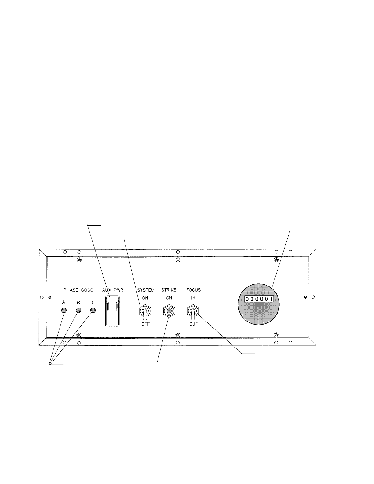
OPERATOR’S CONTROL PANEL
Circuit Breaker, Auxilliary Power
Indicator Lights,
Phase Detection
Toggle Switch, POWER ON-OFF
Pushbutton Switch,
IGNITE
Elapsed Time Meter
(HOURS)
Toggle Switch,
FOCUS IN-OUT
2
Page 5

INSTRUCTIONS FOR REMOVING AND INSTALLING A TYPE “THS” XENON BULB
IN A SEL10 FIXTURE
NOTE
FAMILIARIZE YOURSELF WITH THE LOCATION AND IDENTIFICATION
OF THE COMPONENTS OF THIS SYSTEM AND ALSO THE NORMAL
OPERATION OF THE SYSTEM BEFORE ATTEMPTING ANY ADJUSTMENT
OR SERVICE.
NOTE
COMPLETELY READ THROUGH AND HAVE A GOOD UNDERSTANDING OF THE
PROCEDURES BEFORE ATTEMPTING TO SERVICE THIS SYSTEM. FAILURE TO
DO SO MAY RESULT IN FATAL INJURY OR EQUIPMENT DAMAGE.
NOTE
THE LAMPHEAD SHOULD BE LOCKED IN THE HORIZONTAL POSITION
DURING ANY SERVICE PROCEDURES.
WARNING
DISCONNECT POWER SOURCE BEFORE SERVICING THIS EQUIPMENT.
WARNING
A PROTECTIVE JACKET, FULL FACE SHIELD, AND PROTECTIVE GLOVES MUST
BE WORN AT ALL TIMES WHEN THE LAMP HEAD IS OPENED WITH A BULB
INSTALLED OR WHEN HANDLING THE XENON BULBS. SERIOUS INJURY MAY
OCCUR IF PROPER SAFETY PRECAUTIONS ARE NOT OBSERVED.
READ ALL ENCLOSED INSTRUCTIONS AND INFORMATION SHEETS BEFORE
HANDLING THE BULB.
WARNING
NEVER OPERATE A FIXTURE WITH AN EXPOSED BULB! THERE IS AN EXTREME
DANGER OF SEVERE BURNS TO EXPOSED SKIN AND EYES FROM THE
ULTRAVIOLET LIGHT EMITTED FROM THE EXPOSED BULB. DAMAGE CAN
OCCUR IN AS LITTLE AS 30 SECONDS OF EXPOSURE. THERE IS ALSO
AN ADDITIONAL DANGER FROM FLYING QUARTZ IF AN
EXPOSED BULB EXPLODES!
EQUIPMENT REQUIRED
1. PROTECTIVE SAFETY EQUIPMENT KIT
2. 7/16" END WRENCH OR SOCKET
3. ALLEN WRENCH 5/32"
3
Page 6
DISASSEMBLY PROCEDURE
PRIOR TO BULB INSTALLATION:
1. RELEASE THE (4) FASTENERS LOCATED AT THE SMALL SIDES OF THE COWL BY PRESSING IN ON THE
FASTENERS AND PULLING FORWARD TO REMOVE THE COWLING.
2. REMOVE THE (2) BRASS BOLTS CONNECTING THE SHORT LEADS TO THE FRONT BULB HOLDER USING A
7/16" WRENCH.
3. REMOVE THE CENTER MOUNTING SCREW, WASHER, AND SPRING FROM THE SPIDER (SEE FIGURE 4,
ITEMS 2, 3, 4) USING A 5/32" ALLEN WRENCH WHILE SUPPORTING THE FRONT BULB HOLDER SO THAT IT
DOES NOT FALL WHEN THE SCREW IS REMOVED.
4. REMOVE THE BULB HOLDER FROM THE FIXTURE.
5. TO DISASSEMBLE THE FRONT BULB HOLDER, REMOVE THE (2) CLAMP RETAINING SCREWS LOCATED ON
THE SIDE OF THE LAMP SWIVEL HUB USING A 5/32" ALLEN WRENCH, AND REMOVE THE CLAMP.
ASSEMBLY PROCEDURE
WARNING
DO NOT REMOVE THE PROTECTIVE COVER FROM THE BULB UNTIL INSTRUCTED TO DO SO!
WARNING
DO EXERT ANY FORCE ON THE QUARTZ PORTIONS OF THE BULB AT ANY TIME!
NOTE
IF THE FRONT BULB HOLDER HAS NOT BEEN DISASSEMBLED, SEE THE LAST STEPS IN THE APPROPRIATE
DISASSEMBLY INSTRUCTIONS.
1. UNTIE THE CORD ON THE ANODE (+) END OF THE PROTECTIVE COVER. DO NOT REMOVE THE COVER
AT THIS TIME!
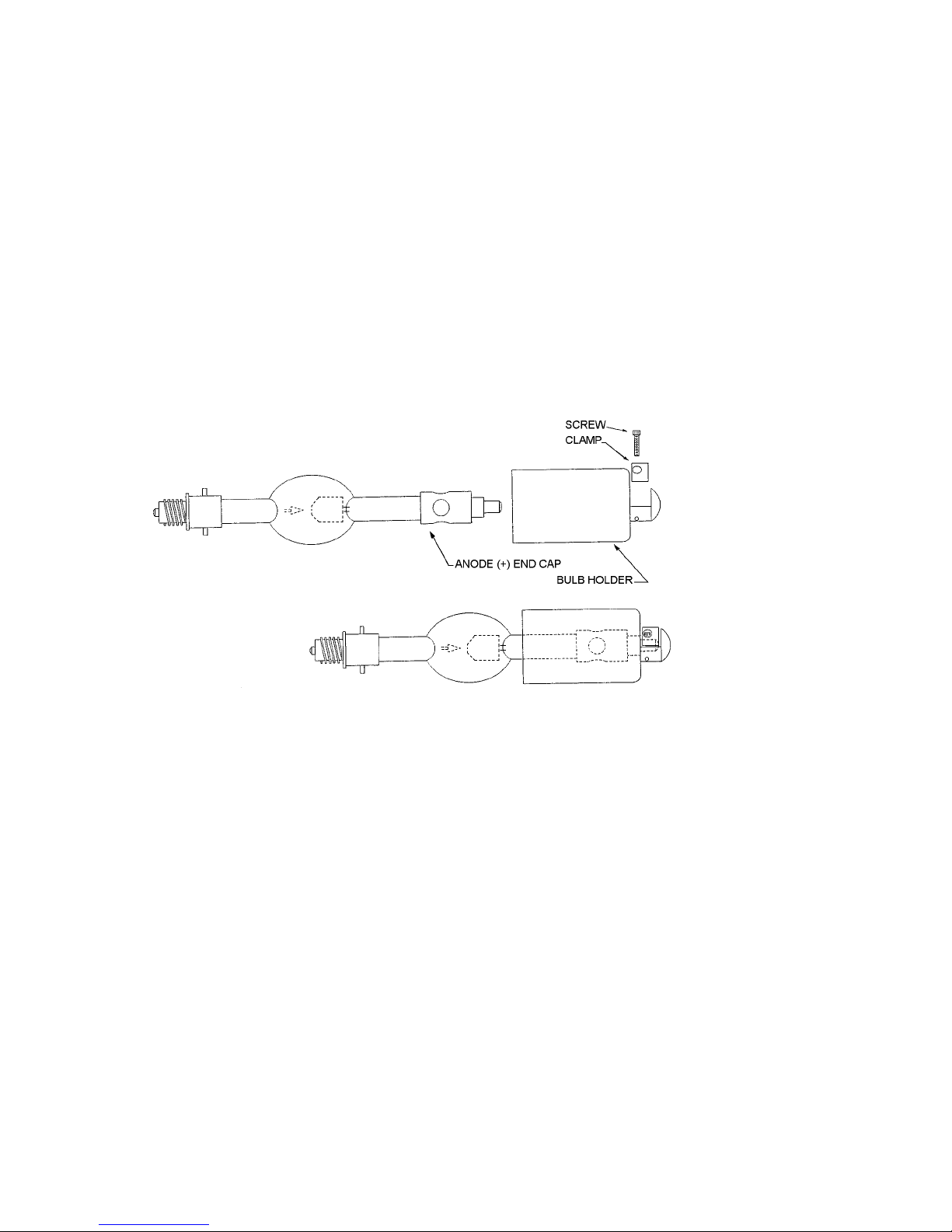
2. FASTEN FRONT BULB HOLDER TO THE BULB BY PLACING THE ANODE END (LARGE ELECTRODE) OF THE
BULB IN THE BULB HOLDER AND ALIGNING THE STUD ON THE END OF THE BULB FERRULE WITH THE
CHANNEL IN THE NOSE OF THE BULB HOLDER BODY. SLIDE THE BULB COMPLETELY DOWN THE
CHANNEL AS FAR AS IT WILL GO.
4
Page 7

WARNING
DO NOT APPLY ANY PRESSURE ON THE BULB WHILE REASSEMBLING THE FRONT BULB HOLDER!
3. REPLACE THE CLAMP AND REINSTALL THE (2) CLAMP RETAINING SCREWS LOCATED ON THE
SIDE OF THE BULB SWIVEL HUB USING A 5/32" ALLEN WRENCH.
4. INSTALL THE BULB INTO THE FIXTURE BY CAREFULLY INSERTING THE CATHODE END OF THE BULB
THROUGH THE OPENING IN THE REFLECTOR. DO NOT STRIKE THE SURFACE OF THE REFLECTOR.
5. INSERT THE END OF THE BULB FERRULE INTO THE OPENING IN THE BULB LAMP HOLDER RECEIVER BLOCK
AND ALIGN THE THREADS BY TURNING THE BULB COUNTERCLOCKWISE UNTIL THE BULB THREADS DROP
INTO THE RECEIVER THREADS.
CAUTION
DO NOT OVERTIGHTEN THE BULB IN THE RECEIVER BLOCK AS THIS MAY CAUSE
THE BULB TO FREEZE IN THE RECEIVER BLOCK, MAKING IT DIFFICULT TO REMOVE.
TIGHTEN THE BULB JUST ENOUGH TO APPLY SPRING PRESSURE TO THE THREADS
BUT NOT SO MUCH AS TO BOTTOM OUT THE LAMP FERRULE COMPLETELY
AGAINST THE RECEIVER BLOCK.
6. GENTLY ROTATE THE BULB CLOCKWISE UNTIL RESISTANCE IS FELT.
7. AT THIS POINT, THE BULB SHOULD BE IN CONTACT WITH THE SPRING PLUNGER ASSEMBLIES. GENTLY
TURN THE BULB AN ADDITIONAL 1/16 - 1/8 OF A TURN TO LOAD THE THREADS WITH THE SPRING
PLUNGERS.
8. SECURE THE FRONT BULB HOLDER TO THE SPIDER WITH THE SHOULDER BOLT, SPRING, AND WASHER
THAT WAS REMOVED DURING DISASSEMBLY.
9. CONNECT THE (2) SHORT LEADS FROM THE SPIDER TO THE FRONT BULB HOLDER USING THE TWO BRASS
BOLTS AND WASHERS THAT WERE REMOVED DURING DISASSEMBLY.
NOTE
ANY TYPE OF ALCOHOL IS SUITABLE FOR CLEANING THE BULB EXCEPT FOR
ALCOHOL THAT HAS BEEN DENATURED USING PETROLEUM PRODUCTS SINCE
THE DENATURING AGENT WILL LEAVE A RESIDUE ON THE QUARTZ ENVELOPE.
10. REMOVE THE PROTECTIVE COVER FROM THE BULB AND CLEAN THE QUARTZ PORTION OF THE BULB
COMPLETELY WITH ALCOHOL.
11. THE INSTALLATION IS NOW COMPLETE. REPLACE THE FRONT COWL AND TEST THE BULB.
12. LOG THE HOUR METER READING AT INSTALLATION.
13. PERFORM THE OUTPUT POWER ADJUSTMENT PROCEDURES.
14. PREFORM THE FOCUS AND X-Y PROCEDURES.
5
Page 8

DISASSEMBLY PROCEDURE
IF THERE IS A LAMP IS INSTALLED IN THE FIXTURE:
1. RELEASE THE (4) FASTENERS LOCATED AT THE SMALL SIDES OF THE COWL BY PRESSING IN ON THE
FASTENERS AND PULLING FORWARD TO REMOVE THE COWLING.
CAUTION
DO NOT PLACE ANY EXCESSIVE FORCE ON THE LAMP WHILE REPLACING THE PROTECTIVE WRAPPER!
2. WRAP THE BULB SECURELY IN THE PROTECTIVE WRAPPER THAT THE BULB WAS ORIGINALLY SHIPPED
WITH.
3. REMOVE THE (2) BRASS BOLTS CONNECTING THE SHORT LEADS TO THE FRONT BULB HOLDER USING A
7/16" WRENCH.
4. REMOVE THE CENTER MOUNTING SCREW, WASHER, AND SPRING (SEE FIGURE 4, ITEMS 2, 3, 4) FROM
THE SPIDER USING A 5/32" ALLEN WRENCH WHILE SUPPORTING THE FRONT BULB HOLDER SO THAT THE
BULB DOES NOT DROP WHEN THE MOUNTING SCREW IS REMOVED.
WARNING
DO NOT EXERT EXCESSIVE FORCE ON THE BULB WHILE UNSCREWING IT FROM
THE REAR BULB HOLDER! THE BULB SHOULD RELEASE FROM THE REAR BULB
HOLDER WITH A VERY LIGHT COUNTER CLOCKWISE ROTATION. IF THIS DOES
NOT HAPPEN, SEE THE PROCEDURE FOR REMOVING A FROZEN BULB.
5. REMOVE THE BULB BY LIGHTLY PUSHING BACK ON THE BULB TO MOVE THE REAR BULB HOLDER TO ITS
REAR MOST POSITION WHILE LIGHTLY TURNING THE BULB IN A COUNTERCLOCKWISE ROTATION. THE
BULB WILL RELEASE FROM THE REAR BULB HOLDER IN APPROXIMATELY 1½ COMPLETE TURNS.
6. REMOVE THE BULB WITH THE FRONT BULB HOLDER ATTACHED FROM THE FIXTURE . PLACE IT ON A
STABLE WORKING SURFACE FOR THE REMOVAL OF THE FRONT BULB HOLDER.
7. TO REMOVE THE FRONT BULB HOLDER FROM THE BULB, REMOVE THE (2) CLAMP RETAINING SCREWS
LOCATED ON THE SIDE OF THE BULB SWIVEL HUB USING A 5/32" ALLEN WRENCH AND REMOVE THE
CLAMP.
8. REMOVE THE BULB HOLDER FROM THE BULB AND PLACE THE BULB INTO ITS SHIPPING CONTAINER FOR
SAFE KEEPING. RESECURE THE PROTECTIVE WRAPPER IF NECESSARY.
REMOVING A FROZEN BULB
1. REPLACE THE FRONT BULB HOLDER RETAINING BOLT TO SUPPORT THE FRONT OF THE BULB WHILE
FREEING THE BULB FROM THE REAR BULB HOLDER.
DO EXERT ANY FORCE ON THE QUARTZ PORTIONS OF THE BULB
WHILE ATTEMPTING TO FREE IT FROM THE REAR LAMP HOLDER!
2. REACH THROUGH THE OPENING IN THE REAR OF THE REFLECTOR AND GRASP THE BULB BY ITS REAR
FERRULE, AND WHILE LIGHTLY PUSHING THE BULB
A COUNTERCLOCKWISE DIRECTION UNTIL THE BULB BEGINS TO ROTATE FREELY.
6
WARNING
BACK
INTO THE RECEIVER BLOCK ,TURN THE BULB IN
Page 9
REMOVING A FROZEN BULB (CONTINUED)
3. ONCE THE BULB IS FREE, DO NOT REMOVE IT COMPLETELY FROM THE REAR LAMP HOLDER.
4. RETURN TO STEP 5 OF THE PRECEDING SECTION.
OUTPUT POWER ADJUSTMENT PROCEDURES
NOTE
FAMILIARIZE YOURSELF WITH THE LOCATION AND IDENTIFICATION OF THE
COMPONENTS OF THIS SYSTEM AND ALSO THE NORMAL OPERATION
OF THE SYSTEM BEFORE ATTEMPTING ANY ADJUSTMENT OR SERVICE.
NOTE
COMPLETELY READ THROUGH AND HAVE A GOOD UNDERSTANDING OF
THE PROCEDURES BEFORE ATTEMPTING TO SERVICE THIS SYSTEM.
FAILURE TO DO SO MAY RESULT IN FATAL INJURY OR EQUIPMENT DAMAGE.
WARNING
DISCONNECT POWER SOURCE BEFORE SERVICING THIS EQUIPMENT.
EQUIPMENT REQUIRED
1. SCREWDRIVER, Flat Blade, Large 3. AMMETER, DC Clamp-On
2. WRENCH, 3/8" 4. VOLT METER, AC/DC
ADJUSTMENT INSTRUCTIONS
1. Remove lower access covers from the ends of the base enclosure by removing the (6) screws
along the sides of each panel with a 3/8" wrench.
2. Note the location and settings of the power supply adjustment taps.
7
Page 10

ADJUSTMENT INSTRUCTIONS (continued)
3. Ignite the xenon bulb and check the current. Allow (30) seconds for the current to stabilize and
provide an accurate reading. If the current is
be necessary to increase or decrease the DC output.
not
within the desired range, extinguish the bulb. It will
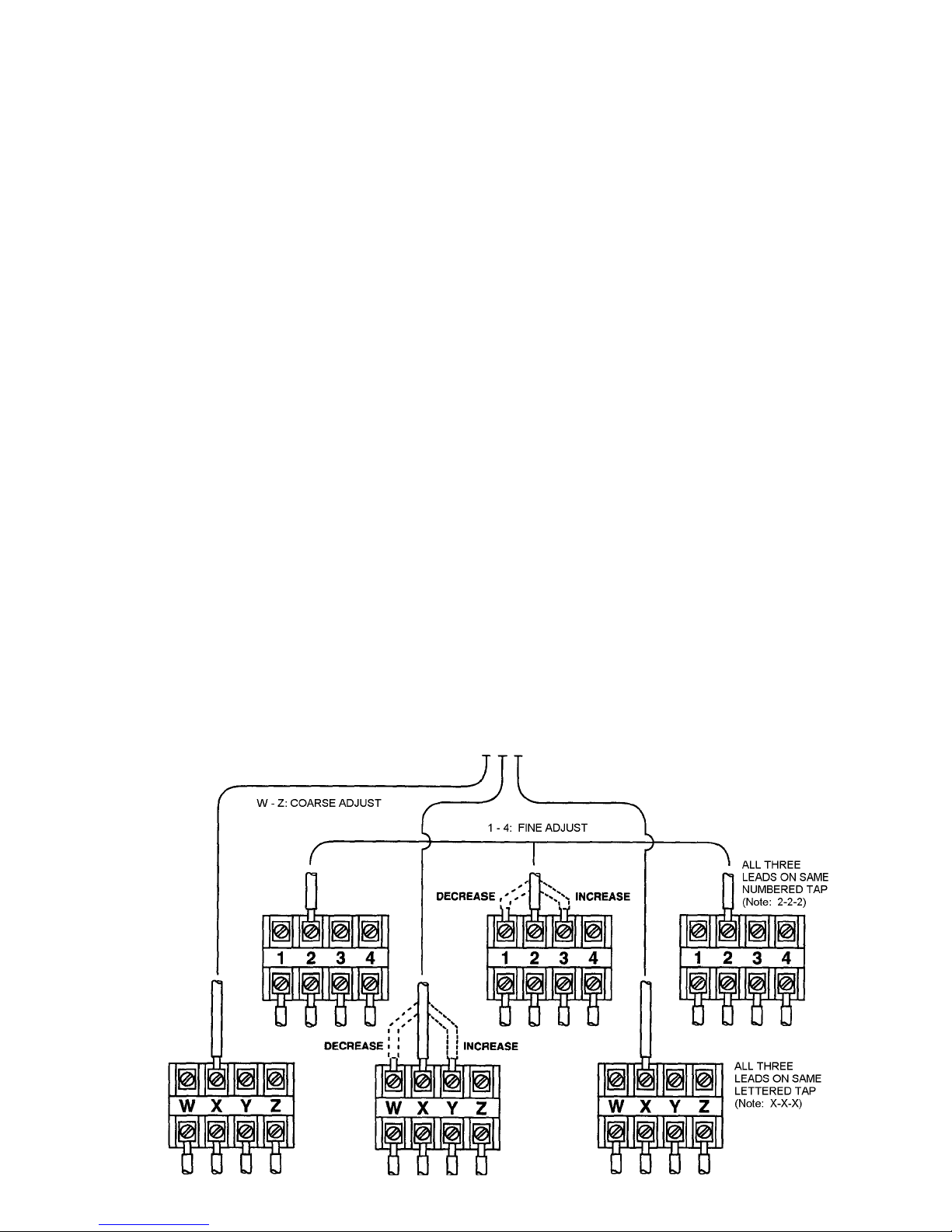
4. Fine adjustment
blocks (TB4, TB5, TB6). Fine taps are numbered 1-2-3-4, with “1” providing the lowest output, increasing to “4,” yielding the highest output. A “fine” tap adjustment raises or lowers the current approximately four amperes. The three fine tap terminal blocks are interconnected by means of a threelead jumper wire assembly attached to like-numbered terminals.
• To
increase
nals, for example, move from terminals “2” to terminals “3.” ALL TAPS MUST BE ON THE SAME NUMBERED
POSITION (1-1-1, 2-2-2, 3-3-3, or 4-4-4). If the DC output is still too low when terminals “4” are interconnected, see the following instructions for adjusting
• To
decrease
terminals, for example, move from terminals “3” to terminals “2.” ALL TAPS MUST BE ON THE SAME
NUMBERED POSITION (1-1-1, 2-2-2, 3-3-3, or 4-4-4). If the DC output is still too high when terminals “1” are
interconnected, see the following instructions for adjusting
the DC output, move the jumper wire assembly to tap the next (3)
5. Coarse adjustment
blocks (TB1, TB2, TB3). Coarse taps are lettered W-X-Y-Z, with “W” providing the lowest output, increasing to “Z” at the highest output. The coarse tap terminals connect to contactor terminals T1, T2,
and T3. The (3) contactor leads must connect to the same lettered step (W-W-W, etc.). A “coarse”
tap adjustment raises or lowers the current approximately twelve amperes.
• To
increase
terminals, for example, move from terminals “W” to terminals “X.” ALL TAPS MUST BE ON THE SAME
LETTERED POSITION (W-W-W, X-X-X, Y-Y-Y, or Z-Z-Z). Place the fine tap jumper on 1-1-1. Ignite the lamp,
check the output, and increase the fine tap setting as required.
the coarse DC output, move each of the contactor leads to tap the next
of the DC current is made to the
NUMBERED
taps found on the upper three terminal
higher
“coarse”
the DC output, move the jumper wire assembly to tap the next (3)
of the DC current is made to the
taps.
“coarse”
LETTERED
taps.
taps found on the lower three terminal
numbered termi-
lower
numbered
higher
lettered
• To
decrease
terminals, for example, move from terminals “Y” to terminals “X.” ALL TAPS MUST BE ON THE SAME
LETTERED POSITION (W-W-W, X-X-X, Y-Y-Y, or Z-Z-Z). Place the fine tap jumper on 1-1-1. Ignite the lamp,
check the output, and increase the fine tap setting as required.
NOTE: Both power supplies should be on the same output setting, i.e.:
6. Set the voltmeter to DC scale and read the arc voltage. The voltage should between 45 and 55 volts
DC. If the actual measured voltage is
7. Inspect tap connections to verify that the terminal is clamping the copper conductor, not the
insulation. Make certain all terminal clamping screws are tight.
8. Whenever making a coarse adjustment, again check the output current and make certain the current is within the desired range. A fine tap re-adjustment is frequently required after changing coarse
taps.
9. After prolonged operation, the light output of the xenon bulb will decrease. This is a normal factor of
bulb aging, and can be compensated by raising the DC output of the xenon power supplies. If the
bulb was first operated at “nominal” current, the power supply output can gradually be increased
to, but
the current as instructed above. Decrease the power supply output to its former “nominal” current
level upon the installation of a new replacement bulb.
the coarse DC output, move each of the contactor leads to tap the next
Power Supply “A” X-X-X, 3-3-3 (or as required)
Power Supply “B” X-X-X, 3-3-3 (or as required)
not
in this range, consult your bulb supplier immediately.
not in excess of,
the maximum current specified by the bulb manufacturer (220 A.). Increase
lower
lettered
8
Page 11

FAMILIARIZE YOURSELF WITH THE LOCATION AND IDENTIFICATION OF THE
COMPONENTS OF THIS SYSTEM AND ALSO THE NORMAL OPERATION OF THE
COMPLETELY READ THROUGH AND HAVE A GOOD UNDERSTANDING OF THE
PROCEDURES BEFORE ATTEMPTING TO SERVICE THIS SYSTEM. FAILURE TO DO
EQUIPMENT REQUIRED
1. ALLEN WRENCH 5/32'
2. #5 WELDERS GLASSES OR VERY DARK SUNGLASSES
THE SEL10 SYSTEMS PROJECT A VERY INTENSE BEAM OF FULL SPECTRUM LIGHT.
THE USE OF DARK GLASSES WHILE ADJUSTING THE BEAM PARAMETERS ON A
LIGHT COLORED REFLECTIVE SURFACE AT A CLOSE DISTANCE IS MANDATORY.
FOCUS AND X-Y ADJUSTMENT INSTRUCTIONS
FOR SYSTEMS w/ ELECTRIC FOCUS
NOTE
SYSTEM BEFORE ATTEMPTING ANY ADJUSTMENT OR SERVICE.
NOTE
SO MAY RESULT IN FATAL INJURY OR EQUIPMENT DAMAGE.
WARNING
WARNING
NEVER LOOK DIRECTLY INTO A LIGHTED FIXTURE'S LIGHT SOURCE.
ADJUSTMENT INSTRUCTIONS
1. Loosen the positioning fasteners and point the lamphead toward a wall, ceiling, or other flat
surface at least 10 feet away.
2. Locate the focus switch located on the control panel on the back of the lamphead housing.
3. Remove the front cowl and locate the X & Y adjustment holes located on the lower small sides of
the fixture at the ends of the front spider arms.
WARNING
SEL10 SYSTEMS PROJECT A VERY INTENSE BEAM OF FULL SPECTRUM LIGHT.
CAUTION MUST BE TAKEN WHEN POINTING THE BEAM AT AN OBJECT AT A
DISTANCE OF LESS THAN 100 FEET WITH THE FOCUS SET FOR A CONVERGING
BEAM. COMBUSTIBLE OBJECTS AND OBJECTS WITH A DARK COLOR MAY UNEXPECTEDLY
IGNITE IF CARE IS NOT TAKEN IN THE FOCUSING AND POSITIONING OF THE BEAM.
4. Energize the fixture and ignite the lamp.
5. Adjust the focus by moving the focus switch up or down to produce a diverging beam pattern
with 2-3 clearly defined rings of light with or without an off center hot spot.
6. Adjust the X & Y adjustment screws using a 5/32" allen wrench to move the inner rings of light to
create concentric rings with the hot spot at the center of the light field. Turning the adjustment
screw clockwise will move the rings toward that adjustment axis and turning the screw
counterclockwise will move the rings away from that adjustment axis.
9
Page 12

FOCUS AND X-Y ADJUSTMENT INSTRUCTIONS (continued)
7. Readjust the focus screw to set the desired beam spread.
8. Replace the front cowl reposition the lamp head and resecure the position locking fasteners.
XENON BULB MAINTENANCE
Allow the blowers to operate for at least (15) minutes after extinguishing the arc. This measure is
required
In order to insure maximum bulb life, the following procedures should be followed every 75 - 100 hours
of operation.
If the fixture is used in a position other than pointed within 15% of vertical, the bulb should be rotated
1/3 of a turn to insure even deposition of the vaporized tungsten generated by the arc inside the bulb.
by the bulb manufacturer to comply with bulb warranty conditions.
BULB ROTATION
ADJUSTMENT PROCEDURES
1. Refer to the instructions for removal and installation of the bulb noting all warnings.
2. Follow the disassembly procedure for a fixture with the bulb installed steps 1 thru 5.
3. When rotating the bulb for removal, continue LIGHTLY pressing rearward on the bulb. The threads
of the bulb will ride out of their current leads and drop into the next set of threads in the receiver
block. When this happens, you will feel the bulb drop down into the receiver block.
4. Immediately stop turning the bulb and reverse direction to screw the bulb in at the new
orientation.
5. Complete reinstalling the bulb per the bulb installation procedure.
POWER LEVEL ADJUSTMENT
Check the output power level of the system and readjust as necessary. Output may be increased to
maintain light output as the bulb ages, but output must remain below 10,000 watts (220 A.). SEE POWER
ADJUSTMENT PROCEDURES preceding.
10
Page 13
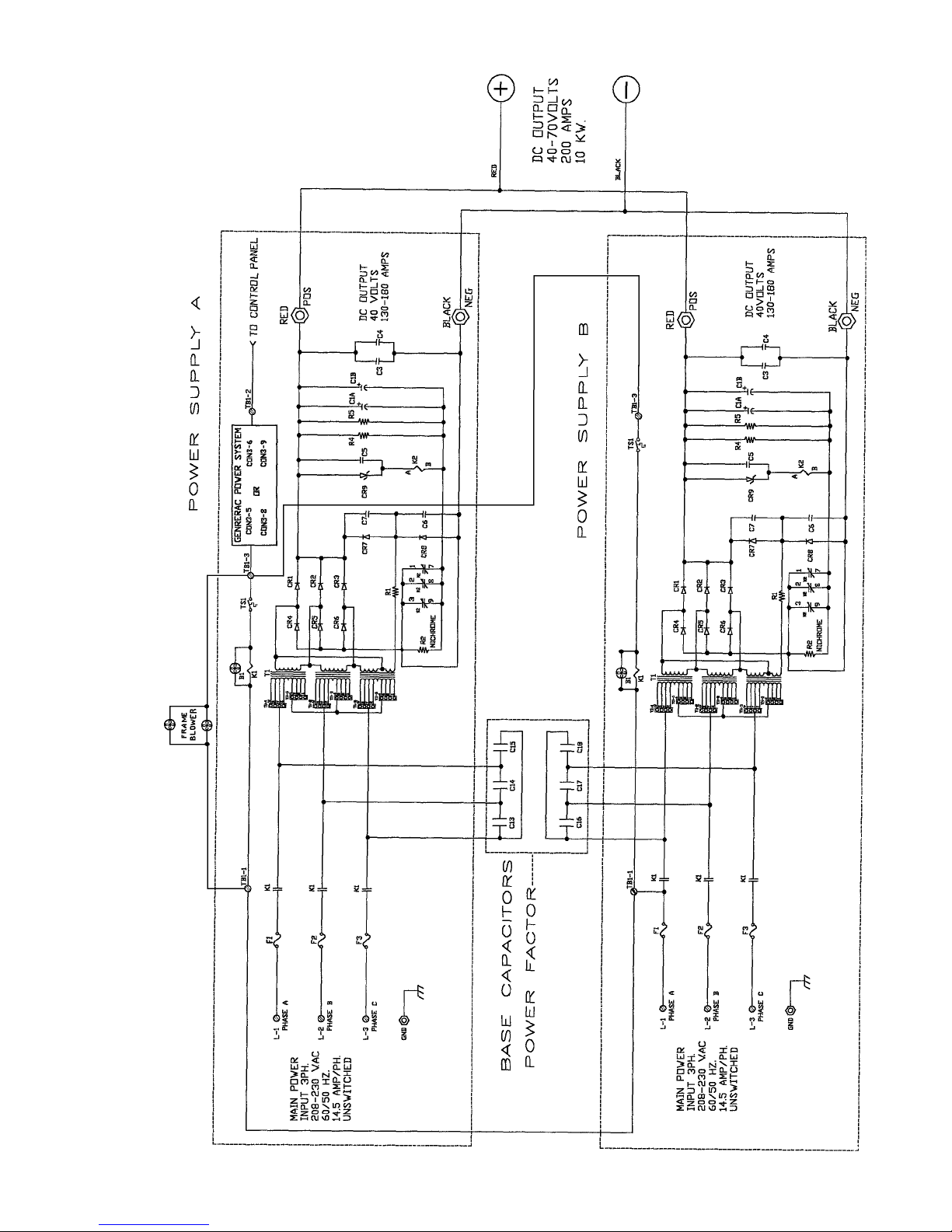
WIRING DIAGRAM
1 of 3
11
Page 14
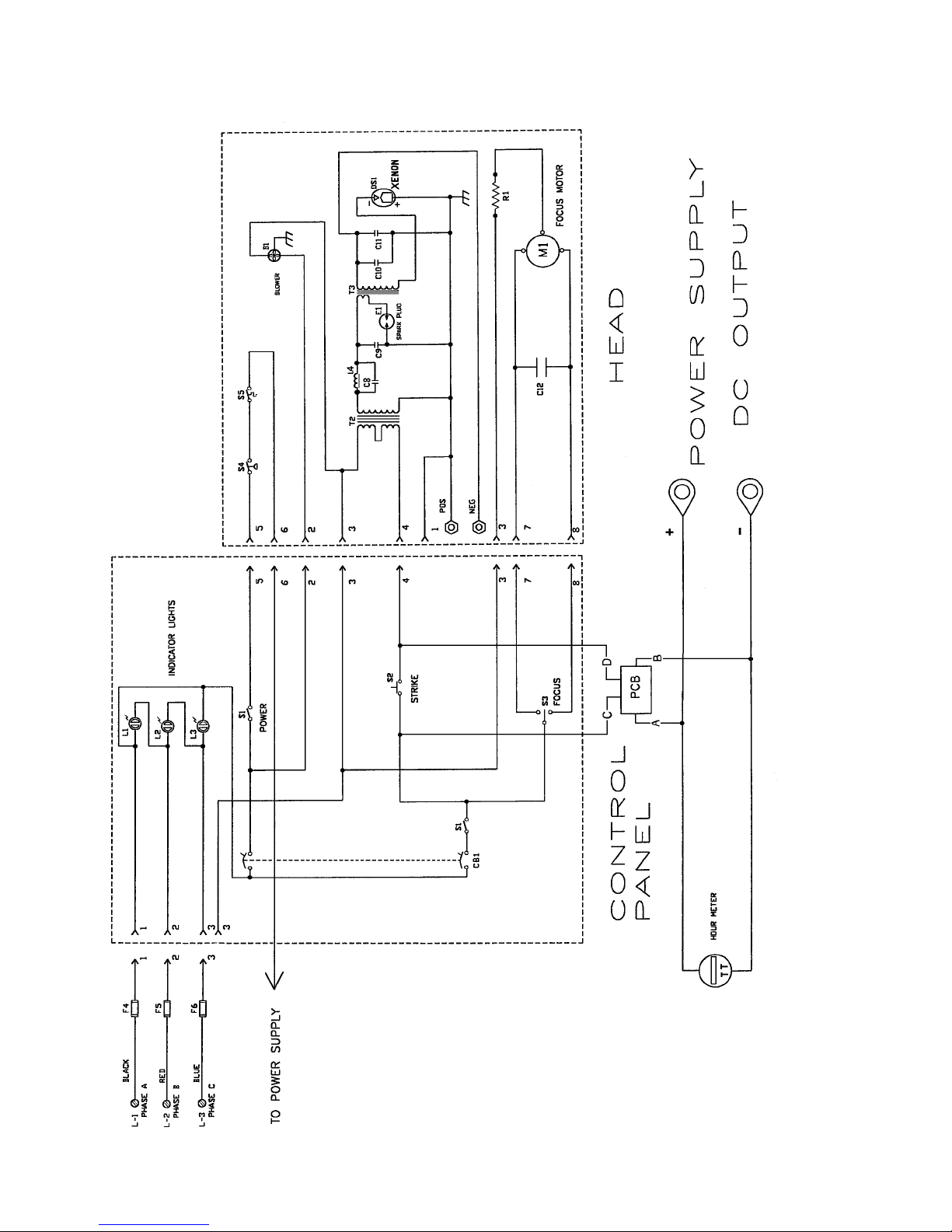
WIRING DIAGRAM
2 of 3
12
Page 15

PARTS LIST, POWER SUPPLIES A & B (Diagram 1 of 2)
Ref.
Desig. Part No. Description
B1 81-33026 Blower
C1A,B 61-08027 Capacitor, 5400 µf, 200 V.
C3,4 81-08005 Capacitor, .33 µf
C5 81-08029 Capacitor,.01 µf, 600 V.
C6,7 81-08025 Capacitor, .005 µf, 800 V.
C13-18 31-08134 Capacitor, 4 µf, 370 V.AC
CR1-3 81-47004 Forward Diode, Rectifier; 100 A. 300 V.
CR4-6 81-47001 Reverse Diode, Rectifier; 100 A. 300 V.
CR7,8 81-47006 Boost Diode, 3 A. 600 V.
CR9 81-17002 Zener Diode, 36 V. 5 W. (1N5365B)
F1-3 31-21038 Fuse, 30 A. 250 V.
K1 81-14001 Contactor
K2 81-45016 Relay, 120 V.AC Coil
R1 81-46026 Resistor, 100 Ohm, 100 W.
R2 92-70026 Nichrome Resistor
R4,5 81-46006 Bleeder Resistor, 2500 Ohm, 10 W.
T1 1249314-3 Power Transformer
TS1 81-61010 Thermal Switch, Open at 210° F.
PARTS LIST, CONTROL PANEL & LAMPHEAD (Diagram 2 of 2)
Ref.
Desig. Part No. Description
B1 32-70228 Squirrelcage Blower, 230 V.AC, 50/60 Hz.
C8 31-08009 Capacitor, .0047 µf
C9 31-08012 Capacitor, 2400 pf, 20 kV.
C10 79127000 Capacitor, .01 µf, 500 V.
C11 31-08011 Capacitor, .47 µf
C12 31-08134 Capacitor, 4 µf, 370 V.AC
CB1 32-61015 Circuit Breaker
DS1 31-30240 Xenon Bulb, 10 kW
E1 31-61009 Spark Plug (Air Gap)
F4-6 21-21002 Fuse, Type 3AG, 5 A.
L1-3 32-30076 Indicator Light
L4 31-71042 Choke, 16 AWG Magnet Wire
M1 32-70328 Bulb Focus Motor, 115 V.AC, 50/60 Hz. (with R1)
R1 11-46110 Resistor, 100 Ohm, 50 W. (incl. with M1)
PCB 40913000 Igniter Printed Circuit Board Assembly (see Diagram 3 of 3)
S1 31-61048 Switch
S2 31-61011 Pushbutton Switch
S3 31-61049 Switch
S4 31-61078 Pressure Switch
S5 31-61134 Thermal Switch, Open at 325° F.
T2 31-64004 Transformer, High Voltage
T3 32-50230 Transformer, RF
TT 31-32004 Elapsed Time Meter
13
Page 16
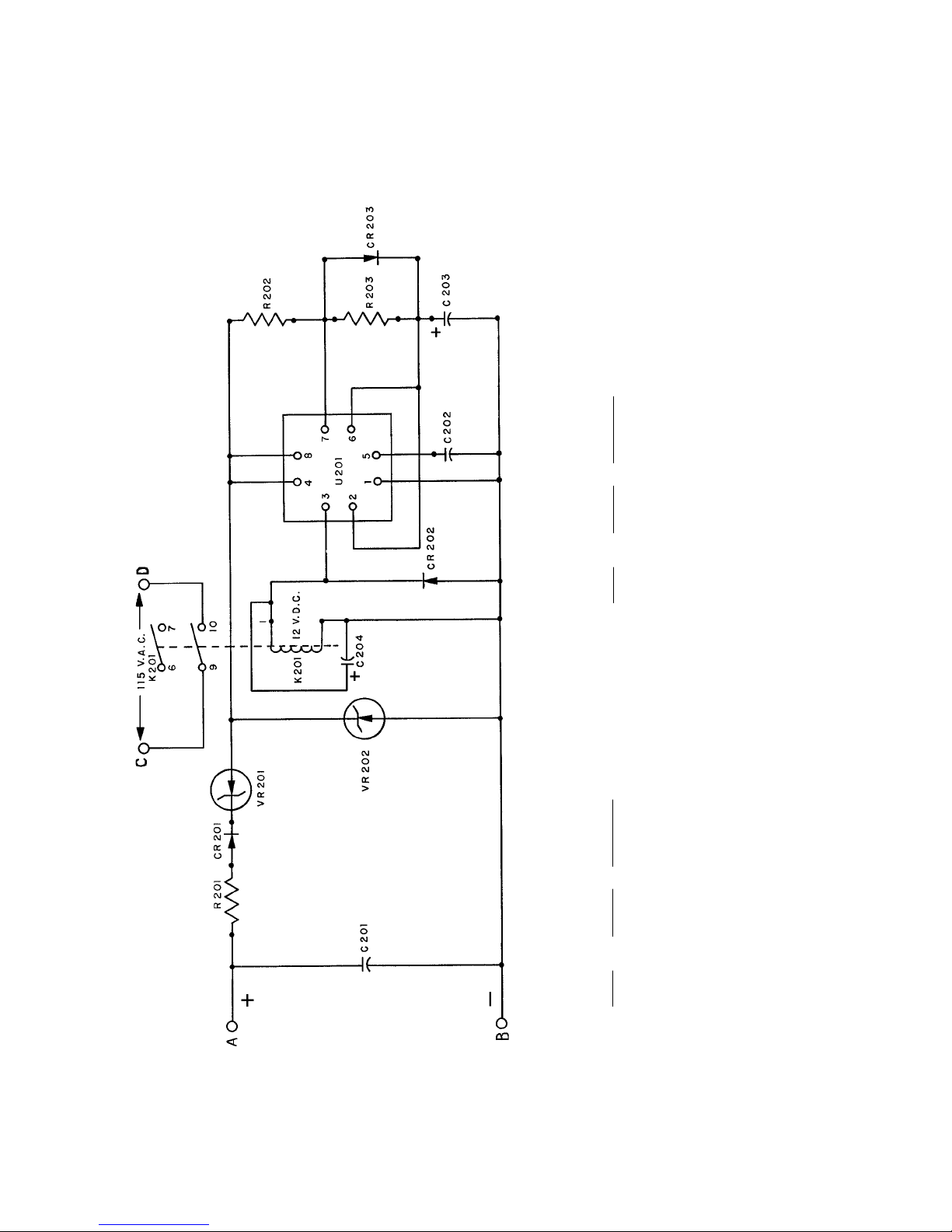
WIRING DIAGRAM
3 of 3
Ref.
Desig. Part No. Description
R201 39157 Resistor, 1k Ohm, 12 Watt
R202 39158 Resistor, 100k Ohm, ½ Watt
R203 39159 Resistor, 200k Ohm, ½ Watt
Ref.
Desig. Part No. Description
C201 88263 Capacitor, .05 µf, 600 WVDC
C202 79127 Capacitor, .01 µf, 600 WVDC
C203 39156 Capacitor, 15 µf, 30/35 WVDC
U201 72185 Timer IC, Motorola MC11455P1
- 39164 IC Socket, (6) Pin
VR201 39211 Zener Diode, 1N5377A
VR202 39162 Zener Diode, 1N4742
- 39145 PC Board (less Components)
* 40913 PCB Assembly, Complete
C204 88249 Capacitor, .1 µf, 600 WVDC
CR201 85112 Diode, 2.5 A. 1000 PRV
CR202 85112 Diode, 2.5 A. 1000 PRV
CR203 85112 Diode, 2.5 A. 1000 PRV
K201 39154 Relay, P&B R10-E1-W2S800
- 39160 Relay Socket
- 39161 Relay Hold-Down Spring
Igniter Printed Circuit Board Assembly
14
Page 17

POWER SUPPLY MAINTENANCE
VERY LITTLE MAINTENANCE is required to keep this power supply in good operating condition. Like
most lighting equipment, cleaning is the most important element.
WARNING
Turn off ALL primary AC power before
making any adjustments or performing serv-
ice procedures. Allow several minutes for
the capacitors to drain stored energy.
Allow the power supply to cool to room
temperature.
1. Remove all accumulated dust and dirt from the rectifier. Vacuum the heat sinks. Make
certain all air inlets and outlets are unobstructed.
2. Check all electrical connections for tightness. Clean, retighten, or replace any discolored
connections or terminals.
3. Apply a drop or two of SAE 20-weight oil to the squirrelcage blower motor bearings.
POWER SUPPLY TROUBLESHOOTING
WARNING: Exercise extreme caution when
taking voltage measurements in a power
“ON” condition. Allow the capacitors (2)
minutes to discharge.
POWER LINE PROBLEMS
PRIMARY POWER (AC source) problems are most commonly (a) complete loss of AC power, or (b)
phase loss, in which one phase loses power.
a) Check line safety switch (“ON”). Check fuses or breakers insupply line. Using an AC voltmeter,
measure input power at contactor terminals L1, L2, L3.
b) When power is lost on one phase, the current ripple will increase and trip the AC line circuit
breaker (where supplied). To detect a lost phase, measure the AC voltage phase-to-phase at
contactor input terminals L1, L2, and L3.
PROBLEMS of this nature, once detected, are generally corrected at the power source, or in the
generator unit.
BOOST CIRCUIT PROBLEMS
THE BOOST CIRCUIT generates the high open circuit (“no load”) DC voltage which, in conjunction
with the igniter pulse, will ignite the xenon bulb. The open circuit voltage should measure at least
110 V.DC.
A TERTIARY WINDING on the main transformer (T1) supplies the source for the Boost Circuit. Three wires
derive from the T1 transformer; two are single conductors, and the third is a soldered pair. The Boost
Circuit should be connected only to the (2) single conductors. Filter capacitors C1A & C1B store
energy and also contribute to bulb ignition.
CONTROL CIRCUITRY
THE MAIN POWER TRANSFORMER is energized by contactor K1, which is pulled by manual
actuation of the lamphead “ON” switch. All lamphouse interlock switches (air pressure & thermal
overload) must also be closed to complete the contactor circuit.
15
Page 18

CONTROL CIRCUITRY (continued)
ANY INTERRUPTION of the control circuit will disable K1 and open the AC circuit to the rectifier. In
addition to the above lamphead interlock switches, thermal switch TS1, mounted to the rectifier heat
sink, will open and disable K1 if the temperature at the heat sinks exceeds 190° F. (88° C.). The TS1
switch will automatically re-set when temperatures fall to safe levels.
POWER CONVERSION PROBLEMS
RECTIFICATION (AC to DC) is performed by bridge diodes CR1 - CR6. CR1, CR2, and CR3 are forward
diodes, and CR4, CR5, and CR6 are reverse diodes. The two types are
not
interchangeable.
AN OPEN DIODE will cause a pronounced flicker in the light output. Two or more open diodes will
disable bulb ignition. A shorted diode will trip the circuit breaker protecting the AC input line. See the
following DIODE TESTING & REPLACEMENT section.
BANKED CAN CAPACITORS C1A & C1B filter the rectified DC output. C1A and C1B capacitors also
store energy to contribute to the open circuit ignition discharge. A shorted capacitor can trip the
AC circuit breaker.
RELAY K2, in the presence of high DC open circuit voltage, will pull and place Resistor R2 in
series with Capacitors C1 and C2. This resistor limits the inrush surge and prolongs the discharge of
C1A & C1B to promote bulb ignition. If K2 relay fails, ignition may become erratic, and R2 may remain
in circuit. With R2 in circuit, ripple will increase to a level noticeable in light output, but not necessarily enough to trip the AC line circuit breaker.
DIODE TESTING & REPLACEMENT
1. Disconnect the diode from its circuit. Inspect for discoloration, oxidation, or loose crimp at lead
junction.
2. A “shorted” diode will show low resistance in both directions. An “open” diode will have infinite
resistance in both directions. An Ohmmeter test is required.
3. a) Analog VOM: Select R x 1 Ohm scale. With meter leads connected in one direction, the
reading should be zero (or nearly so); reversing the meter leads should show very high resistance. If the diode does not exhibit these characteristics, replace it. NOTE DIODE TYPE: forward
or reverse.
b) Digital VOM: Select “Diode Test.” With meter leads connected in one direction, the reading
should be “OL” (overload); reversing the meter leads should display approximately .4 volt.
If the diode does not exhibit these characteristics, replace it. NOTE DIODE TYPE: forward or reverse.
4. Carefully clean the area of the heat sink in which the diode mounts. Apply heat sink compound
(Radio Shack #276-1373 or equivalent) using a wood or plastic spatula or stick. A thin layer is
adequate.
WARNING
HEAT SINK COMPOUND IS HIGHLY CAUSTIC.
Do not apply with fingers; keep away from
eyes. Carefully follow ALL the instructions
printed on the package.
5. Install the new diode and tighten securely for maximum mechanical contact and electrical conduction. Clean and firmly secure the lead terminal to the buss.
16
Page 19

POWER SUPPLY TROUBLESHOOTING
Contactor does not energize (no audible “click”).
1. Line safety switch open. Turn “ON.”
2. Circuit breaker or fuse in AC line open. Check AC source.
3. Faulty contactor coil or loose connection at coil terminals. Repair or replace.
Contactor pulls but lamphouse igniter does not fire.
1. Faulty contactor contacts. With coil energized, check for continuity across the contacts from the
“L” side to the “T” side; repair or replace if defective.
2. Insufficient DC output. See INSTALLATION section; increase taps as required.
3. Faulty igniter.
4. Low open circuit voltage (less than 110 V.DC).
a) Check ceramic resistor R1; should be in circuit and measure 100 Ohms.
b) Check boost diodes CR7 and CR8. See preceding DIODE TESTING section.
c) Check filter capacitors C1A and C1B. Replace if defective.
5. Defective igniter printed circuit board assembly. Press STRIKE switch to override; do not hold STRIKE
switch longer thatn
one second
to prevent damage to high voltage transformer.
Bulb requires multiple ignition pulses to light.
1. Insufficient DC output. See INSTALLATION section; set taps as required.
2. Faulty K2 relay. Replace if defective.
3. Faulty or expired xenon bulb. Check for darkened envelope, worn electrodes; replace if required.
4. One or more faulty bridge diodes. See preceding DIODE TESTING section.
Bulb goes out during operation.
1. Excessive heat at rectifier heat sinks; thermal switch TS1 opening. Check for free air flow, blower(s)
operating at full speed. Check for loose connection.
2. Open lamphead thermal interlock switch.
Excessive flicker in light output.
1. Improper tap setting. All taps must be on same numbered or lettered step.
2. Faulty bridge diode. See preceding DIODE TESTING section.
3. Faulty xenon bulb. Check for cracked or sagging electrode(s).
4. Open filter capacitor C1A or C1B. Replace if defective.
Bridge diodes (CR1-6) fail repeatedly.
1. Insufficient air flow; defective blower. Clean, repair, or replace as required.
2. Incorrect replacement diode. Use only the specified rated diode(s).
17
Page 20

The SEL10 lamphead requires very little maintenance to keep it in good working order. Cleanli-
ness is the most important element.
LAMPHEAD MAINTENANCE
The reflector should be cleaned periodically with a soft, clean, lint free cloth to remove any
dust from the reflecting surface. If excessively soiled, use of a mild commercial glass cleaner (Windex
®
or equivalent) is acceptable; USE NO ABRASIVE CLEANERS.
The xenon bulb should be checked occasionally for the presence of foreign material on the
envelope. Any dirt or other foreign material should be removed promptly. Use only alcohol and a
clean cloth to clean the bulb; rinse with distilled water and dry carefully. DO NOT touch the bulb with
bare fingers, and observe all safety procedures when working around the bulb.
The inside of the lamphead and the impeller blades of the blower should be cleaned periodically, depending on the dust conditions at each installation.
The xenon lamphead does not require any lubrication other than at the blower. This should be
lubricated with two or three drops of non-detergent motor oil every four to six months. The oil holes are
on top of the motor.
Check all electrical connections periodically for tightness, especially the DC leads at the xenon
bulb and igniter.
Follow the recommendations of the xenon bulb manufacturer regarding periodic bulb rotation.
It is a general practice to rotate the bulb 180° at 50% of warranty life. After rotating a bulb, increase
current to the maximum allowable level, and operate the bulb at this level for 10 to 12 hours. This
period will re-excite the thorium in the cathode tip and allow the new arc pattern to establish. After
the 10 or 12 hours, return the current setting to its previous level.
Always allow the lamphead blower to operate for at least ten minutes after extinguishing the
bulb. Failure to do so will shorten bulb life.
LAMPHEAD TROUBLE CHART
ALLOW THE LAMPHEAD to cool, with all blowers operating, for at least (20) minutes before opening.
Normal Operation:
The lamphead blower will start when the generator first supplies power to the SEL10. When the
control panel SYSTEM switch S1 is in the “ON” position, the elapsed time meter will operate, the power
supply blowers will start, and the AC circuit (5 - 6) to the xenon power supply will energize the circuitry
necessary to supply DC voltage to the igniter and bulb.
The DC open circuit (“no load”) voltage will be detected by the igniter printed circuit board,
which in turn will close the circuit to the igniter. There will be an audible high voltage arc ping at the
spark gap in the igniter and at the xenon bulb. The bulb should ignite immediately after one or two of
these high voltage pulses, and the lamp current will adjust to the sustaining level set at the xenon
power supply. The STRIKE switch may be pressed to override a defective igniter PC board.
Troubleshooting:
If the xenon bulb does not ignite, observe the following operational sequences for assistance in
locating and isolating the trouble area.
When the three phase indicator lights are “ON,” the AC circuit in the power supply is trouble
free up to the terminal block (L1, L2, L3) in the power supply. Check the 230 V.AC control circuit at the
blower leads at terminals #2 and #3.
18
Page 21

Troubleshooting (continued)
With the squirrelcage blower operating, the air plenum should compress, completing the circuit
to the igniter. The elapsed time meter should start to indicate elapsed time. If this meter does not
operate, check for continuity at the SYSTEM switch. Check continuity of the air pressure switch; should
read 0 Ohms between “NO” and “COM” when actuated. A defective elapsed time meter will not
prevent bulb ignition.
With the SYSTEM switch in the “ON” position, a distinct high voltage arc ping at the igniter spark
gap should be heard, and a flash from the xenon bulb should be visible, as DC voltage is applied to
the bulb electrodes. If the high voltage ping or the flash at the ammeter is not apparent, check for
110 V.DC “No Load” voltage between the lamphouse and power supply. An adequate level of “no
load” voltage will close the relay on the igniter PC board and fire the igniter. Momentarily pressing the
STRIKE switch will bypass the igniter PC board.
If the correct voltage for the power supply is not measured, the problem is in the lamphouse/
power supply interconnecting cable(s), or in the power supply. See the preceding troubleshooting
guide for additional instructions and tests.
If the high voltage arc is audible at the lamphouse, and the bulb does not flash, replace the
bulb and attempt ignition with the new bulb.
Using the new bulb, if the high voltage arc is audible at the lamphouse, the flash of the bulb is
visible, and ignition is not sustained, the problem is in the power supply.
If the high voltage arc is not audible or the flash of the bulb visible, the trouble is in the igniter or
the igniter printed circuit board assembly.
Bulb fails to ignite.
1. AC power not on to lamphouse. If 230 V.AC not read at 3 & 4, check power supply.
2. Air pressure switch S4 not closing. Check for unobstructed hose; clean if required. Check continu-
ity between “NO” and “COM”; replace if defective.
3. Faulty S1 “SYSTEM” switch. Check for voltage at 5 & 6; check for loose wiring. Replace if defective.
Bulb fails to ignite; ping audible, bulb flash visible.
1. Inadequate DC output from xenon power supply. Set power supply output to correct range
required for bulb wattage.
2. Faulty or expired xenon bulb. Replace as required.
Bulb fails to ignite; ping audible, no bulb flash.
1. Faulty xenon bulb. Check for cracked electrodes or darkened envelope. Replace if defective.
2. Ignition pulse shorting to ground. Inspect DC leads for burned insulation; dress leads away from
grounded metal components.
No high voltage ping audible; MODE switch in “MAN.” and LAMP switch in “ON.”
1. Loss of AC control voltage. Check xenon power supply for open thermal switch.
2. Little or no DC “No Load” voltage. Measure DC “No Load” voltage at rectifier output terminals.
3. Defective igniter PC board. Press STRIKE switch to bypass; do not hold switch for longer than
second.
Repair or replace PC board.
4. Defective “STRIKE” switch. Check for continuity across terminals.
5. Faulty igniter. Check for 230 V.AC at 3 & 4; adequate DC “No Load” measured. Replace igniter if
defective.
one
19
Page 22

Troubleshooting (continued)
Bulb goes out during operation.
1. Xenon power supply overheated; thermal switch open. Check power supply blower(s), air inlets
and outlets unobstructed.
2. Lamphead blower B1 failed or obstructed. Clean dust and dirt from blower squirrelcage. Check
for 230 V.AC at 2 & 3; replace blower if defective.
3. Lamphouse air pressure switch S4 faulty. Check for correct actuation; replace as required.
Excessive light flicker.
1. Faulty or aged bulb. Check for cracked or sagging electrodes; replace if defective.
2. Excessive ripple in DC output. See power supply manual.
Reduced light output.
1. Normal bulb aging. Increase output current. DO NOT EXCEED MAXIMUM CURRENT SPECIFIED BY
BULB MANUFACTURER.
2. Soiled reflector. Clean using commercial glass cleaner. USE NO ABRASIVES.
3. Soiled cowl glass. Clean as required.
Extremely long duration between ignition pulses.
1. Low DC “No Load” from xenon power supply. Check “No Load” voltage; see power supply
manual.
2. Defective spark gap E1. A “Ping” sound is normal; excessive “Hissing” is abnormal. Replace if
defective.
3. Low AC voltage to lamphead. Check for 230 V.AC at 3 & 4; if below 190 volts, check generator.
4. Defective timer chip on igniter PC board. Repalce as required.
20
Page 23
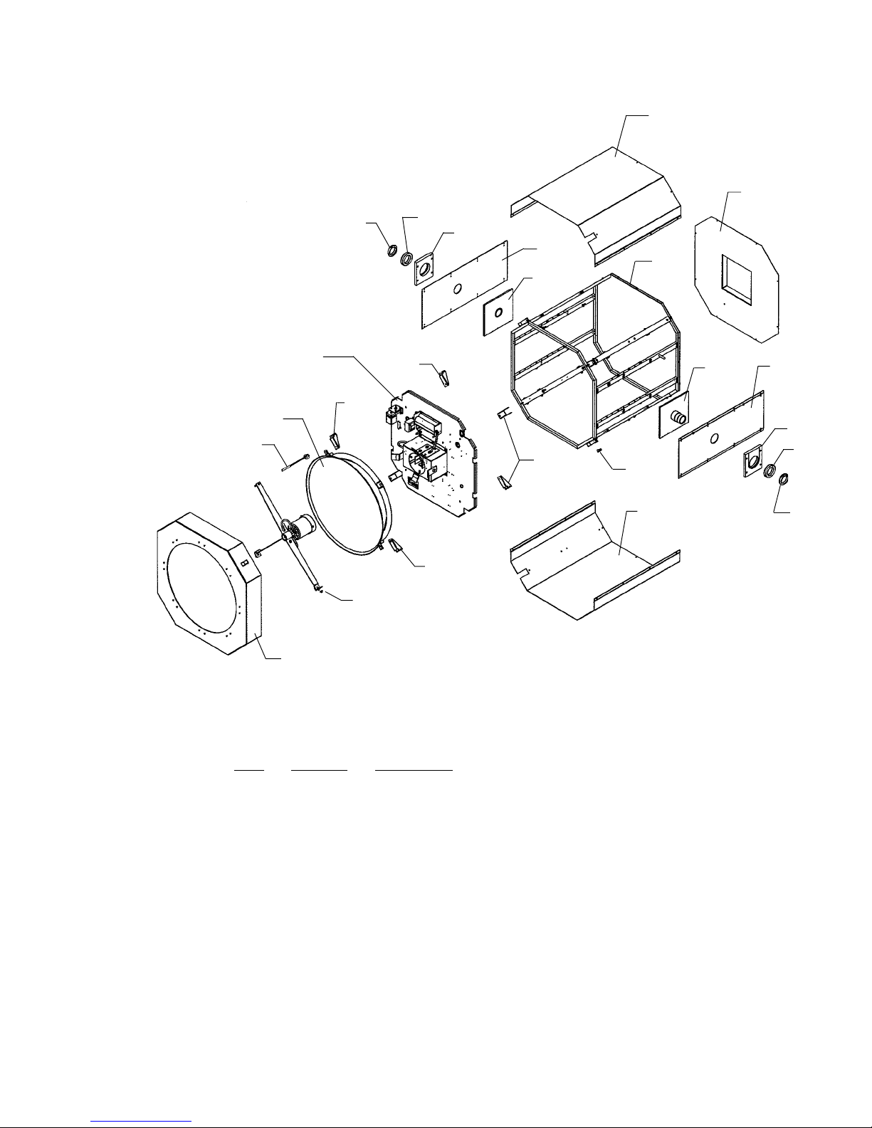
Lamphead Assembly
1
FIGURE 1
2
See Figure 2
See Figure 4
13
8
11
11
See Figure 4
7
11
6
5
3
4
4 5
6
11
9
10
7
8
12
PARTS LIST
Figure 1
Item Part No. Description
1 32-40668 Top Cover
- 41-51984 Mounting Screw, 10-32 x 1/2" Pan Head Philips
2 32-40674 Rear Cover Plate
- 31-98159 Weatherstripping (Order by foot)
- 41-51984 Mounting Screw, 10-32 x 1/2" Pan Head Philips
- 32-40667 Air Intake Cover, Welded Assembly
- 00894A00 Split Lockwasher, #10
- 41-51984 Mounting Screw, 10-32 x 1/2" Pan Head Philips
4 32-40693 Vertical Tilt Axle (2 req’d.)
- 41-51581 Mounting Screw, 1/4-20 x 2" Socket Head
- 41-70061 Flat Washer, 1/4"
- 41-70062 Split Lockwasher, 1/4"
5 32-40705 Side Cover Panel
- 41-51984 Mounting Screw, 10-32 x 1/2" Pan Head Philips
6 32-40697 Bearing Housing (2 req’d.)
- 41-51888 Mounting Screw, 3/8-16 x 1-1/4" Hex Head
- 41-70074 Flat Washer, 3/8"
- 41-70075 Split Lockwasher, 3/8"
21
Page 24

PARTS LIST, Figure 1 (continued)
Item Part No. Description
7 31-04015 Ball Bearing (2 req’d.)
8 31-04037 Nut, Bearing Retaining (2 req’d.)
9 32-40698 Catch, Cowl Release (4 req’d.)
10 32-40669 Bottom Cover
- 41-51984 Mounting Screw, 10-32 x 1/2" Pan Head Philips
11 32-40638 Mounting Bracket (8 req’d.)
- 41-51984 Mounting Screw, 10-32 x 1/2" Pan Head Philips
- 01715000 Flat Washer, #10
12 32-50527 Front Cowl Assembly
- 32-40702 Front Cowl, Welded Assembly
- 31-18004 Push Latch, 4 req’d.
- 31-98777 Glass, Front Cowl
- 31-98136 Gasket (not shown)
- 32-20331 Pad, Silicone Rubber (8 req’d.)
- 32-40699 Mounting Bracket (8 req’d.)
- 41-51926 Mounting Screw, 1/4-20 x 1" Flat Philips Head
NOT SHOWN
31-30240 Xenon Bulb, 10 kW
22
Page 25
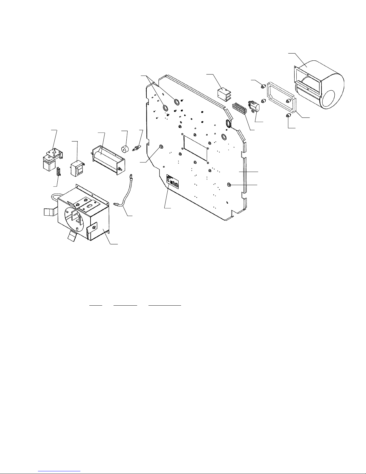
FIGURE 2
Bulkhead Assembly
1
11
10
12
13
16
15
14
7
9
See Figure 3
17
3
4
5
2
3
6
7
8
PARTS LIST
Figure 2
Item Part No. Description
1 32-70228 Squirrelcage Blower, 220 V.AC, 50/60 Hz.
2 32-20329 Blower Gasket
3 31-98182 Mounting Stud, 10-32 (4 req’d.)
- 01715000 Flat Washer, #10
- 00894A00 Split Lockwasher, #10
- 41-35012 Hexnut, 10-32
4 31-08134 Capacitor, 4 µf, 370 V.AC
- 31-10025 Capacitor Clamp
- 41-51876 Mounting Screw, 6-32 x 1/2" Pan Head
- 01550000 Split Lockwasher, #6
- 01553000 Flat Washer, #6
5 31-62011 Terminal Block Section (8 req’d.)
- 31-62012 Terminal Block End Plate (2 req’d.)
- 41-51889 Mounting Screw, 8-32 x 5/8" Pan Head Philips
- 41-70059 Flat Washer, #8
- 41-70060 Split Lockwasher, #8
6 32-40643 Bulkhead Plate
- 41-51381 Mounting Screw, 1/4-20 x 1" (to Fig. 1 Item 11 Bracket)
- 41-70062 Split Lockwasher, 1/4"
- 32-40770 Bulkhead Spacer, 1/4" Aluminum (4 ea. as req’d.)
23
Page 26

PARTS LIST, Figure 2 (continued)
Item Part No. Description
7 41-51438 Contact Screw, Bulkhead; 1/4-20 x 1" Hex Head, Brass
- 00835000 Flat Washer, 1/4" Brass
- 41-35058 Hex Nut, 1/4" Brass
- 41-70060 Split Lockwasher, 3/8"
- 32-50238 Positive Lead Assembly, Bulkhead to Front Spider (not shown)
8 31-34031 Name & Data Plate, SEL10
9 31-98083 Negative Lead, RF Coil to Bulb Receiver
- 41-51754 Contact Screw, 1/4-20 x 1/2" Hex Head
- 41-70065 Lockwasher, 1/4" Internal Tooth
- 00835000 Flatwasher, 1/4"
10 11-46001 Fixed Resistor, 100 Ohm, 50 W. (with Item 11)
- 41-51791 Mounting Screw, 4-40 x 1/2" Pan Head
- 41-70057 Split Lockwasher, #4
11 32-70328 Motor & Bracket Assembly, 115 V.AC, 50/60 Hz. (incl. Item 10)
- 41-51984 Mounting Screw, 10-32 x 1/2" Socket Head
- 00894A00 Split Lockwasher, #10
12 31-64004 High Voltage Transformer (T2)
- 41-51889 Mounting Screw, 8-32 x 5/8" Pan Head
- 41-70059 Flat Washer, #8
- 41-70060 Split Lockwasher, #8
13 32-50230 RF Coil (T3)
- 41-51889 Mounting Screw, 8-32 x 5/8" Pan Head Philips
- 41-70059 Flat Washer, #8
- 41-70060 Split Lockwasher, #8
14 39110000 Capacitor (C9)
- 41-51906 Mounting Screw, 8-32 x 1/2" Pan Head Philips
- 41-70053 Flat Washer, #8 Brass
15 31-61009 Spark Plug (E1)
- 41-70025 Shakeproof Wsher, 1/2"
- 41-35154 Hex Nut, Metric
16 41-98127 Grommet Material, Plastic
17 31-62025 Terminal Block, DC
- 41-51984 Mounting Screw, 10-32 x 1/2" Pan Head Philips
- 01715000 Flat Washer, #10
- 32-70363 Bulkhead Assembly, Complete (Items 1-17; incl. Fig. 3)
24
Page 27
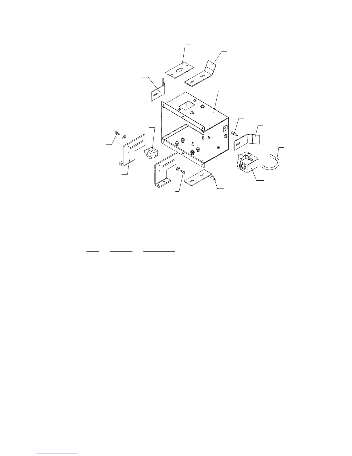
FIGURE 3
Air Plenum Assembly
1
2
5
3
4
11
5
8
10
9
8
2
7
6
PARTS LIST
Figure 3
Item Part No. Description
1 32-40287 Insulator, Negative Lead
- 41-51607 Mounting Screw, 8-32 x 5/8" Socket Head
2 32-40666 Bonding Bracket, Large (2 req’d.)
- 41-51766 Mounting Screw, 1/4-20 x 1/2" Socket Head
- 41-70061 Flat Washer, 1/4"
3 32-40676 Air Plenum, Welded Assembly
- 41-51766 Mounting Screw, 1/4-20 x 1/2" Socket Head
- 41-70061 Flat Washer, 1/4"
4 31-20001 Hose Fitting (2 req’d.)
5 32-40672 Bonding Bracket, Small (2 req’d.)
- 41-51766 Mounting Screw, 1/4-20 x 1/2" Socket Head (to Item 16)
- 41-70061 Flat Washer, 1/4"
6 32-20324 Hose, Pressure Line
7 31-61078 Pressure Switch (S4)
- 41-51984 Mounting Screw, 10-32 x 1/2" Truss Head Philips
8 41-51755 Shoulder Screw, 10-24 x 3/8" Socket Head, 2 req’d.
- 41-70061 Flat Washer, 1/4"
9 31-98770 Insulated Receiver Rail, Right
- 41-51578 Mounting Screw, 1/4-20 x 1" Hex Head
- 41-70061 Flat Washer, 1/4"
- 41-70062 Split Lockwasher, 1/4"
10 31-98769 Insulated Receiver Rail, Left
- 41-51578 Mounting Screw, 1/4-20 x 1" Socket Head
- 41-70061 Flat Washer, 1/4"
- 41-70062 Split Lockwasher, 1/4"
11 32-50050 Rear Bulb Receiver, Threaded
25
Page 28
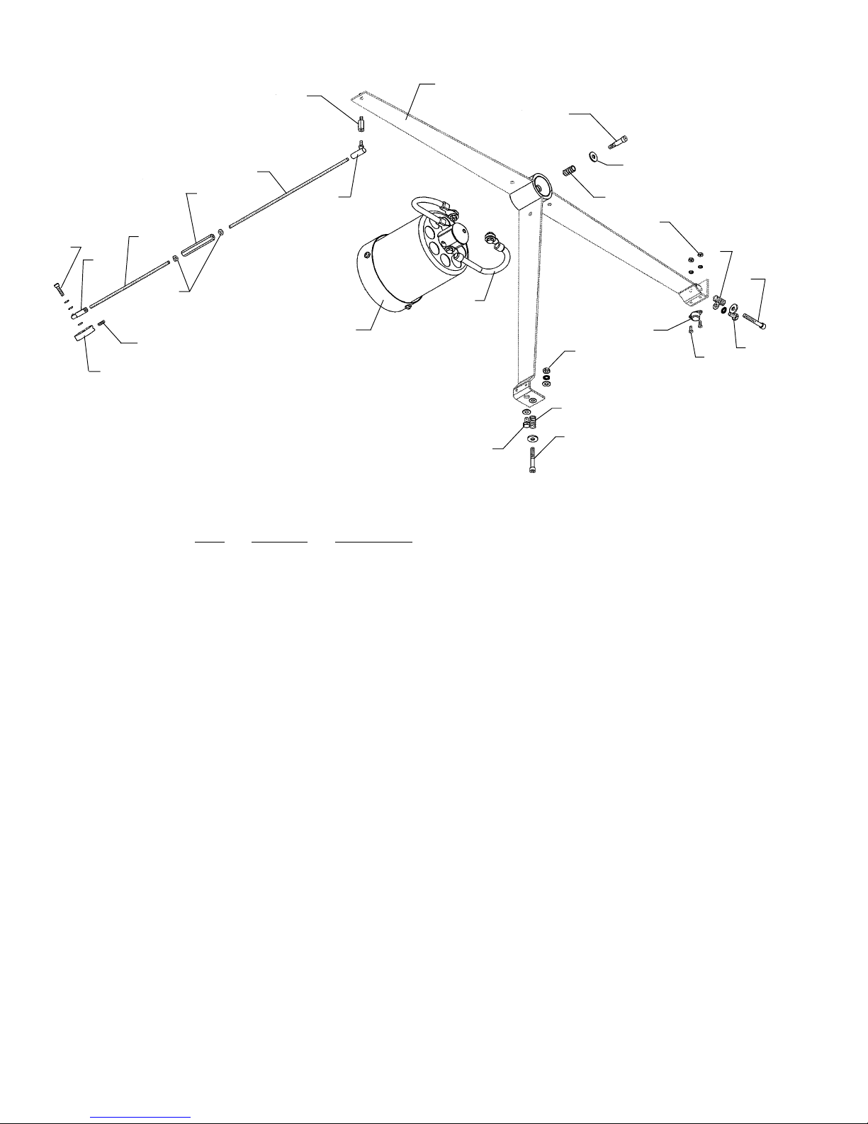
FIGURE 4
Front Spider Assembly
23
1
2
16
26
17
15
18
14
21
19
20
22
12
4
13
11
6
7
8
PARTS LIST
Figure 4
Item Part No. Description
1 32-40293 Front Spider, Welded Assembly
2 41-51767 Shoulder Screw, 1/4-20 x 3/4"
3 41-70061 Spacer, 1/4" Stainless Steel
4 31-58025 Compression Spring
5 01723000 Hexnut, 6-32
- 41-70012 Lockwasher, #6
6 31-58024 Compression Spring
7 41-51580 Screw, 1/4-20 x 1-1/4" Socket Head
- 41-70061 Flat Washer, 1/4"
8 41-51754 Contact Screw, Spider; 1/4-20 x 1/2" Hex Head, Brass
- 41-70035 Flat Washer, 1/4" Brass
- 41-35058 Hex Nut, 1/4-20 Brass (ref. Item 11)
9 41-51735 Screw, 6-32 x 3/8" Round Head Philips
10 81-61010 Thermal Switch (S5)
11 41-35058 Hex Nut, 1/4-20 Brass
12 32-50244 Positive Lead, Spider to Bulb Holder (2 req’d.)
- 41-51754 Contact Screw, 1/4-20 x 1/2" Hex Head Brass
13 32-50549 Bulb Holder Assembly
- 41-51562 Clamping Screw, 1/4-20 x 1" Socket Head (2 req’d.)
14 41-51990 Set Screw, 8-32 x 1/2"
15 32-20019 Focus Cam
16 41-51887 Screw, 10-32 x 1/2" Socket Head
- 00894A00 Split Lockwasher, #10
17 31-98133 Rear Ball Joint
18 31-60089 Threaded Rod, Rear
19 41-35012 Locknut, 10-32 Hex
20 31-98753 Turnbuckle, 10-32
21 31-60071 Threaded Rod, Front
22 31-98131 Front Ball Joint
23 41-98096 Standoff, 10-32 x 3/4"
- 41-35163 Nut, 10-32 NyLock
3
10
5
6
7
8
9
Page 29
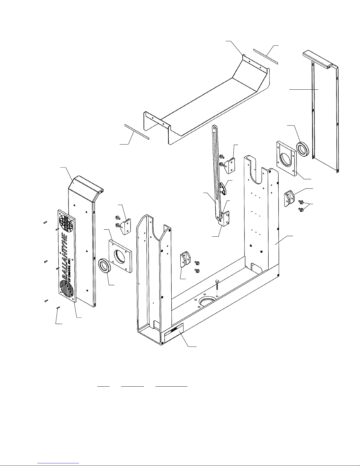
FIGURE 5
Yoke Assembly
1
2
3
4
2
6
3
12
11
10
6
5
6
7
5
9
8
6
4
14
15
Item Part No. Description
1 32-40664 Base Cover
- 41-51984 Mounting Screw, 10-32 x 1/2" Pan Head Philips
- 01715000 Flat Washer, #10
2 31-60115 Cover Gasket, Weather Seal (2 req’d.)
3 32-40690 Side Cover (2 req’d.)
- 41-51984 Mounting Screw, 10-32 x 1/2" Pan Head Philips
- 01715000 Flat Washer, #10
- 00894A00 Split Lockwasher, #10
13
PARTS LIST
Figure 5
27
Page 30

PARTS LIST, Figure 5 (continued)
Item Part No. Description
4 31-04015 Ball Bearing (see Figure 1, Item 7)
5 32-40697 Bearing Housing (2 req’d.)
- 41-51888 Mounting Screw, 3/8-16 x 1-1/4" Hex Head
- 41-70074 Flat Washer, 3/8"
- 41-70075 Split Lockwasher, 3/8"
6 32-20302 Hoist Bracket (4 req’d.)
7 41-51204 Mounting Screw, 3/8-16 x 1" Hex Head
- 41-70074 Flat Washer, 3/8"
- 41-70075 Lockwasher, 3/8"
8 32-40728 Yoke Frame, Welded Assembly
9 32-20297 Mounting Bracket, Pivot Lock Slide
- 41-51206 Mounting Screw, 3/8-16 x 1" Hex Head
- 41-70074 Flatwasher, 3/8"
- 41-70075 Lockwasher, 3/8"
10 32-20260 Spacer Washer, 1/2" (3 req’d.)
11 32-40716 Slide, Pivot Lock
- 41-35165 Hex Nut, 1/2-13
- 41-70166 Flat Washer, 1/2"
12 31-28035 Clamping Knob
- 32-20330 Spacer Washer, 1/2"
13 31-34028 DANGER Decal
14 32-20310 BALLANTYNE Nameplate
15 41-51887 Screw, 10-32 x 1/2" Socket Head
28
Page 31
1
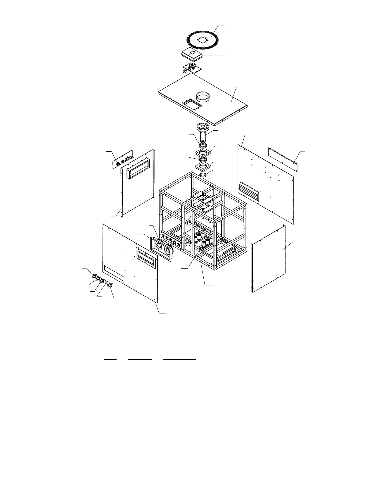
FIGURE 6
Base Assembly
2
3
4
19
18
17
23
22
16
15
20
21
13
6
6
5
7
9
10
7
8
11
12
Item Part No. Description
1 32-40744 Pan Lock Plate
- 41-51981 Mounting Screw, 1/2-13 x 2-1/2" Hex Head
- 41-70164 Split Lockwasher, 1/2"
- 41-70163 Flatwasher, 1/2"
2 32-40755 Cover Assembly, Horizontal Pan Lock
3 32-50544 Pan Lock Assembly
- 41-51596 Mounting Screw, 10-32 x 1" Socket Head
- 00894A00 Split Lockwasher, #10
- 01715000 Flatwasher, #10
4 32-40750 Top Cover, Welded Assembly
- 41-51984 Mounting Screw, 10-32 x 1/2" Pan Head Philips
- 01715000 Flat Washer, #10
- 00894A00 Split Lockwasher, #10
14
PARTS LIST
Figure 6
29
Page 32

PARTS LIST, Figure 6 (continued)
Item Part No. Description
5 32-20304 Axle, Horizontal Pan
6 31-14016 Ball Bearing
7 32-20294 Bearing Block
- 41-51984 Mounting Screw, 10-32 x 1/2" Pan Head Philips
- 01715000 Flat Washer, #10
- 00894A00 Split Lockwasher, #10
8 31-35026 Lock Collar
9 32-40722 Back Cover Panel, Welded Assembly
- 41-51984 Mounting Screw, 10-32 x 1/2" Pan Head Philips
- 01715000 Flat Washer, #10
- 00894A00 Split Lockwasher, #10
10 32-20310 Nameplate
- 41-51596 Mounting Screw, 10-32 x 1" Socket Head
11 32-40715 End Cover Panel
- 41-51984 Mounting Screw, 10-32 x 1/2" Pan Head Philips
- 01715000 Flat Washer, #10
- 00894A00 Split Lockwasher, #10
12 32-40742 Base Frame, Welded Assembly
13 31-08134 Capacitor, Power Factor (C13-C18)
- 31-10025 Capacitor Clamp (6 req’d.)
- 41-51914 Clamp Mounting Screw, 8-32 x 3/8" Pan Head
- 32-40724 Capacitor Mounting Plate (2 req’d.)
- 41-51984 Mounting Screw, 10-32 x 1/2" Pan Head Philips
- 01715000 Flat Washer, #10
- 00894A00 Split Lockwasher, #10
14 32-40721 Front Cover Panel, Welded Assembly
- 41-51984 Mounting Screw, 10-32 x 1/2" Pan Head Philips
- 01715000 Flat Washer, #10
- 00894A00 Split Lockwasher, #10
15 31-13041 Green Receptacle (Ground)
16 31-13412 Cover Plate
- 51-40044 Female XLR Plug, Type AA3F
17 31-13029 Blue Receptacle (AC Phase)
18 31-13039 Red Receptacle (AC Phase)
19 31-13040 Black Receptacle (AC Phase)
- --- Mounting Hardware, Items 15-19
- 41-51984 Mounting Screw, 10-32 x 1/2" Pan Head Philips
- 01715000 Flat Washer, #10
- 00894A00 Split Lockwasher, #10
20 32-40710 Blower Panel, Welded Assembly
- 41-51984 Mounting Screw, 10-32 x 1/2" Pan Head Philips
- 01715000 Flat Washer, #10
- 00894A00 Split Lockwasher, #10
21 71627000 Blower, 220 V.AC, 50/60 Hz. (2 req’d.)
- 41-51984 Mounting Screw, 10-32 x 1/2" Pan Head Philips
- 01715000 Flat Washer, #10
- 00894A00 Split Lockwasher, #10
22 32-40712 End Panel, Welded Assembly
- 41-51984 Mounting Screw, 10-32 x 1/2" Pan Head Philips
- 01715000 Flat Washer, #10
23 32-70335 Control Panel Assembly (see facing page)
- 41-51984 Mounting Screw, 10-32 x 1/2" Pan Head Philips
- 01715000 Flat Washer, #10
- 00894A00 Split Lockwasher, #10
30
Page 33
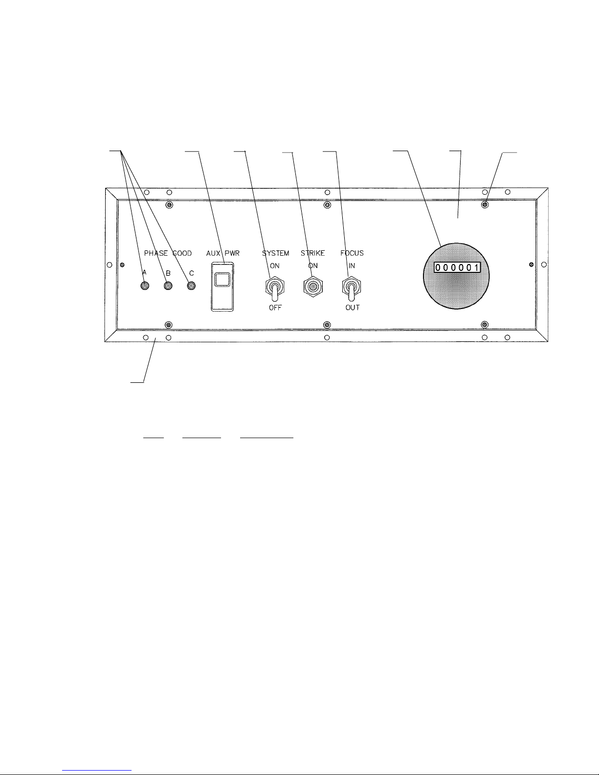
PARTS LIST, Figure 6 (continued)
24
22 (ref.)
25 26
27
28
29
30 31
Item Part No. Description
24 32-30076 Indicator Light (L1-L3)
25 32-61015 Switching Circuit Breaker (CB1)
- 32-61126 Switch Boot
26 31-61048 Toggle Switch (S1)
- 11-98150 Switch Boot
27 31-61011 Pushbutton Switch (S2)
28 31-61049 Toggle Switch (S3)
- 31-61165 Switch Boot
29 31-32004 Hour Meter (TT)
30 32-40681 Control Panel Plate (less Components)
31 41-51984 Mounting Screw, 10-32 x 1/2" Pan Head Philips
- 01715000 Flat Washer, #10
- 00894A00 Split Lockwasher, #10 Mounting Screw
31
Page 34
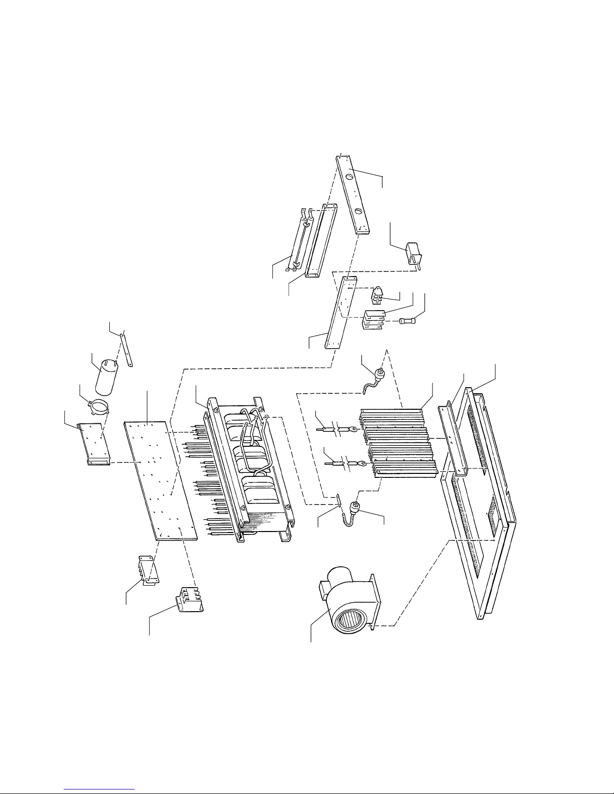
FIGURE 7
Xenon Power Supply
9
10
8
111213
7
4
3
7
17
14
15
2
5
1
6
16
18
19
20
21
24
23
32
22
Page 35

PARTS LIST
Figure 7
Item Part No. Description
1 82-40264 Capacitor Mounting Bracket
2 61-06001 Capacitor Clamp (2 req’d.)
3 61-08027 Filter Capacitor, 5400 µf, 200 V.DC (C1A, C1B)
4 82-40248 Shorting Bar
5 82-40047 Terminal Board Mounting Plate, Phenolic
6 91-64012 Power Transformer, 5000 Watt; 208/230 V.AC Input (T1)
Item 6 Transformer includes Item 5 Mounting Plate & (6) Item 24 Terminal Blocks.
7 82-40040 Support Bracket, Rectifier Heat Sinks
8 81-46026 Ceramic Resistor (R1,2), 100 Ohm, 100 W.
9 82-40254 Heat Sink Mounting Plate, Phenolic
10 81-45016 Relay (K2)
11 21-62067 Terminal Block Segment (3 req’d.)
- 21-62066 Terminal Block End
12 31-21054 Fuse Block
13 31-21038 Fuse, 30 A. 250 V. (F1, F2, F3)
14 32-40006 Chassis Plate, Welded Assembly
15 82-40255 Heat Sink Mounting Plate
16 82-20032 Heat Sink
17 81-47004 Forward Diode (CR1,2,3), 100 A. 300 V. (1N3290)
18* 61-71010 Positve Lead (Red)
19* 61-71009 Negative Lead (Black)
- 94129000 Ring Terminal (2 per lead req’d.)
20 91-98031 Buss Bar (3 req’d.)
21 81-47001 Reverse Diode (CR4,5,6), 100 A. 300 V. (1N3290R)
22 81-33026 Squirrelcage Blower, 230 V.AC, 50/60 Hz. (B1)
23 81-14003 Contactor (K1)
24 81-62001 Tap Terminal Block (6 req’d.)
40913000 Igniter Printed Circuit Board Assembly
* Order by
NOT SHOWN
foot
33
Page 36

34
Page 37

Strong Entertainment Lighting
EQUIPMENT WARRANTY
Strong Entertainment Lighting agrees that its products shall be free
from defects in materials and workmanship for a period of one (1)
year, from the date of original shipment from its factory. This warranty
is nontransferable and applies to the original purchaser only. Said
warranty will not apply if equipment is used in conditions of service for
which it is not specifically intended. The manufacturer is not responsible for damage to its apparatus through improper installation,
physical damage or poor operating practice.
If any device is found to be defective under the warranty, the buyer
should notify the manufacturer. Such equipment will be repaired or
replaced, at manufacturer’s option, free of all charge except transportation, F.O.B. its factory. Any such repair or replacement by the
manufacturer shall constitute fulfillment of all obligations to the purchaser. This warranty does not include troubleshooting expense,
labor charges associated with service calls, and disassembly or
reassembly of the lamp system. Should such a repair or replacement
require an on-site service call, the Purchaser shall bear the responsibility for all costs and associated expenses. The manufacturer does not
assume responsibility for any unauthorized repairs to its products,
even though defective, and unauthorized parts or repairs shall void
this warranty.
This warranty is the only warranty given with the manufacturer’s
products. There are no warranties of merchantability of fitness for a
particular purpose or other warranties or representations of any kind,
express or implied, which are made with respect to these products.
The remedies of the Owner set forth in this warranty are exclusive. In
no event shall the buyer be entitled to recover for incidental, special
or consequential damages, arising from the sale or use of these
products, including but not limited to loss of profits or revenue, other
commercial losses, inconvenience, delay, labor, repairs, or other cost
of rental or replacement equipment.
This warranty excludes any and all incidental damage that may be
caused by xenon bulb explosions. The bulbs used in manufacturer’s
products are not included in this warranty; however, they are covered by the bulb manufacturer’s warranty.
Page 38

 Loading...