

Page 1

Betriebsanleitung
Hebel−Endschalter
HHEV
Service Instructions
Lever Limit Switches
HHEV
Nr. / No. 157−00000
Version: B
Antriebstechnik
von Stromag
Diese Betriebsanleitung soll den
Benutzer dazu befähigen, das
Stromag − Produkt sicher und
funktionsgerecht zu handhaben,
rationell zu nutzen und sachge−
recht zu pflegen, so daß die Ge−
fahr einer Beschädigung oder
Fehlbedienung ausgeschlossen
wird.
Stromag − Produkte entsprechen
dem Qualitätsstandard nach DIN
ISO 9001.
This service manual shall enable
the user to operate the Stromag
product safely and effectively, to
use it sensibly and to maintain it
properly so as to exclude the pos−
sibility of any damage or incorrect
operation.
Stromag products comply with
the Quality Standard to DIN ISO
9001.
The German wording prevails for
sense and tenor of these instruc−
tions.
Page 2

Hebel − Endschalter / Lever Limit Switches
HHEV
Nr./No. 157 − 00000
Inhalt Kapitel
Technische Daten 1
Typschild 1.1
Typschlüssel 1.2
Technische Daten 1.3
Mechanische Hebeldaten Tabelle 1,
Kontaktdaten Tabelle 2, Kontaktanschlüsse 1.4
Einsatz und bestimmungsgemäße Verwendung 1.5
Sicherheitshinweise 2
Arbeitssicherheits − Symbol 2.1
Achtungshinweis "Achtung" 2.2
Arbeitssicherheits − Hinweise 2.3
Elektromagnetische Verträglichkeit 2.4
Transport 3
Verpackung 3.1
Zerlegungsgrad 3.2
Empfindlichkeit 3.3
Zwischenlagerung 3.4
Lieferumfang 3.5
Aufbau, Wirkungsweise, Konstruktionsmerkmale 4
Einbau des Hebel − Endschalters 5
Content Chapter
Technical data 1
Nameplate 1.1
Key to types 1.2
Technical data 1.3
Gear data − Table 1, Contact data − Table 2
Contact connections 1.4
Application and intended use 1.5
Safety guidelines 2
Symbol for safety at work 2.1
Instructions "Caution" 2.2
Safety instructions for working 2.3
Electromagnetic compatibility 2.4
Transportation 3
Packing 3.1
Pre − mounting condition 3.2
Sensitivity 3.3
In − process stocking 3.4
Delivery extent 3.5
Construction, functioning, constr. characteristics 4
Assembly of the lever limit switch 5
Inbetriebnahme 6
Kontakteinstellung 6.1
Normaleinstellung "V50" 6.1.1
Feineinstellung "FV50" 6.1.2
Doppel − Feineinstellung DFV" 6.1.3
Normaleinstellung "V70" 6.1.4
Feineinstellung "FV70" 6.1.5
Betrieb 7
Betriebsbedingungen 7.1
Schutzarten 7.2
Instandhaltung 8
Ausführungen mit Heizwiderstand 9
Ersatzteilhaltung und Kundendienst 10
Ersatzteilhaltung 10.1
Daten für Ersatzteilbestellung 10.2
Ersatzteil − und Kundendienstanschrift 10.3
Aufgeführte Normen und Vorschriften 11
Commissioning 6
Contact adjustment 6.1
Normal adjustment "V50" 6.1.1
Precise adjustment "FV50" 6.1.2
Double precision adjustment DFV" 6.1.3
Normal adjustment "V70" 6.1.4
Precise adjustment "FV70" 6.1.5
Operation 7
Operation conditions 7.1
Protections 7.2
Maintenance 8
Executions with heating resistor 9
Spare parts stocking and after − sales service 10
Spare parts stocking 10.1
Data for spare parts orders 10.2
Address of the after − sales service 10.3
Listed standards and regulations 11
Datum / Date 07.2004
1
Page 3
Hebel − Endschalter / Lever Limit Switches
HHEV
Nr./No. 157 − 00000
1 Technische Daten
1.1 Typschild
Folgende Daten befinden sich auf dem Typschild:
Stromag − Adresse − CE − Kennzeichnung
Typ − Bezeichnung ......
Sach − Nr. 160.....
Auftrags − Nr. 160.....
Schaltleistung (A) − Spannung (V)
− Schutzart
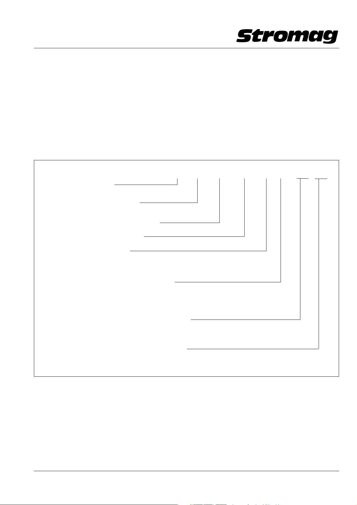
1.2 Typschlüssel
Schaltertyp / Switch type
Anzahl der eingebauten Kontakte
Number of contacts fitted
Art der eingebauten Kontakte (s. Tabelle 2)
Type of contacts fitted (see table 2)
Feineinstellung / Precise adjustment
1 Technical data
1.1 Nameplate
The following data is indicated on the nameplate:
Stomag address − CE − Mark
Type ......
Part − No. 160.....
Order Ref. No. 160.....
Output (A) − Voltage (V)
− Protection
1.2 Key to types
HHEV − 5 90 F V 50 A1 H1...
Verstellbarkeit der Schaltpunkte
Setting of switching points
Durchmesser der eingebauten Nockenscheiben
Dia. of the fitted cam discs
Durchmesser 70mm (nicht bei Kontakt 52 u. 53)
Dia. 70 mm (not with contact 52 and 53)
Schaltergröße / Switch size
A1 − Kontaktraum Größe 1 bis 5 Kontakte
− contact space size 1 max. 5 contacts
A2 − Kontaktraum Größe 2 bis 8 Kontakte
− contact space size 2 max. 8 contacts
Zusatzbenennungen / Additional designations
H
H
− PTC − Heizung/heater 12 − 36V AC/DC
1
− PTC − Heizung/heater 110 − 250V AC/DC
2
OA − ohne Anschlag / without limit stop
1.3 Technische Daten
Hebelweg sowie weitere technische Daten sind der He−
bel − und Kontakttabelle zu entnehmen, s. Tabelle 1
und 2.
1.3 Technical data
The lever way as well as the other technical data for
every limit switch type are indicated in the lever and con−
tact table, see table 1 and 2.
Datum / Date 07.2004
2
Page 4

Hebel − Endschalter / Lever Limit Switches
HHEV
Nr./No. 157 − 00000
Tabelle / Table 1
Mechanische Hebeldaten bei Hebellänge 100 mm
Mechanical lever data at lever length 100 mm
Nutzbarer Hebelweg nach jeder Seite (mechanisch begrenzt)
85°
Usable lever way in each direction (mechanically limited)
Schaltpunktabstand stufenlos einstellbar nach jeder Seite
0 − 85°
Switching point distance infinitely adjustable in each direction
Nachlaufwinkel am Hebel nach jeder Seite
Overrun angle at the lever in each direction
85°
− nutzb. Hebel−
winkel / usable
lever angle
Rückschaltwinkel am Hebel bei Schnappkontakten / Reset angle at the lever in each direction
Kontakt / Contact 51; 52 a) aus Linksdrehung / from ccw − rotation 1,5°
b) aus Rechtsdrehung / from cw − rotation 1,5°
Kontakt / Contact 80; 90 a) aus Linksdrehung / from ccw − rotation 2,8°
b) aus Rechtsdrehung / from cw − rotation 2,8°
Schaltpunkt Wiederholgenauigkeit am Hebel / Switching point repetitive accuracy at the lever
Kontakt / Contact 51; 52 a) aus Linksdrehung / from ccw − rotation 0,06°
b) aus Rechtsdrehung / from cw − rotation 0,1°
Kontakt / Contact 80; 90 a) aus Linksdrehung / from ccw − rotation 0,1°
b) aus Rechtsdrehung / from cw − rotation 0,1°
Drehrichtungsangaben der Nockenscheiben bzw. des Antriebshebels mit Blickrichtung auf die Schaltwelle
Indication of direction of rotation of the cam discs or the drive lever resp. with line of sight to the switching shaft
Max. Antriebsgeschwindigkeit an der Antriebs − Hebel − Rolle
215 m/min
Max. drive speed at the drive lever roller
Entsprechend der Drehzahl der Schaltwelle
Corresponding to the speed of the switching shaft
Min. Antr. − Geschwindigkeit bei Kontakt 51 und 52 (nur bei Wechslerfunktion)
340 min
0,004 m/min
−1
rpm
Min. drive speed with contact 51 and 52 (with change − over function only)
Entsprechend der Drehzahl der Schaltwelle
Corresponding to the speed of the switching shaft
Min. Antr. − Geschwindigkeit bei Kontakt 80 und 90 (nur bei Wechslerfunktion)
0,007 min
0,21 m/min
−1
rpm
Min. drive speed with contact 80 and 90 (with change − over function only)
Entsprechend der Drehzahl der Schaltwelle
Corresponding to the speed of the switching shaft
0,347 min
−1
rpm
Datum / Date 07.2004
3
Page 5
Hebel − Endschalter / Lever Limit Switches
HHEV
Nr./No. 157 − 00000
Tabelle / Table 2
Kontaktdaten / Contact Data
Kontakt−
Art
Contact
type
51
3)
52
53
80
81
90
1) T = Oms
2) EN 60947 − 5 − 1
3) Goldkontakte für Schaltlasten <24 V − 100 mA / Gold contacts for switching loads < 24 V − 100 mA
Schaltsystem
Switch actuation
Schnapp
Snap action
Schnapp
Snap action
Tast
Push action
Schnapp
Snap action
Tast
Push action
Schnapp
Snap action
Zwangstren−
nung des
Öffners
Positive ope−
ning of nor−
mally closed
contact
nein
no
ja
yes
ja
yes
ja
yes
ja
yes
ja
yes
2)
2)
Schaltleistung / Switching rating
AC DC
Ith A Ui V 24V A 1)110V A
6
10
10
10
10
10
250
250
250
400
400
400
4
1
1
10
10
4
0,8
0,7
0,7
1,5
1,5
1,5
1)
220V A
0,4
0,3
0,3
0,5
0,5
0,5
mech. Lebens −
dauer in Mio.
Schaltungen
Mech. life in
mio switching
operations
1)
>30
>10
>30
>10
>10
>10
Kontakt:
Contact:
2
4
1
80
81
313
51
90
22
1424
21 13
52
53
DD1 40187H
Datum / Date 07.2004
4
Page 6
Hebel − Endschalter / Lever Limit Switches
HHEV
Nr./No. 157 − 00000
1.4 Kontaktanschlüsse
Die Kontaktanschlüsse befinden sich immer innerhalb
des Schaltergehäuses. Für die Kabeleinführung befin−
den sich standardmäßig 3 Kabeleinführungsbohrun−
gen im Hebelgehäuse. Die Bohrungen sind mit
M20x1,5 Blindstopfen verschlossen. Je nach Bedarf
werden die Blindstopfen kundenseitig durch Kabel −
einführungen ersetzt. Die Bohrungen befinden sich auf
der oberen und den beiden seitlichen Hebelgehäusen.
Die Kabelenden gelangen durch das Hebelgehäuse an
die Anschlußklemmen der Kontakte. Jeder Kontakt ist
mit einem Berührungsschutz ausgerüstet. Mit Aus−
nahme bei Kontakt 51 brauchen die Berührungs−
schütze zur Verdrahtung nicht entfernt werden.
Bei Kontakt 51 werden vor der Verdrahtung alle Berüh−
rungsschütze in Kontaktstößelrichtung vom Kontakt
abgezogen. Die anschließende Verdrahtung erfolgt
nach dem Verdrahtungsschema im Bild 1.
Nach der Verdrahtung muß jeder Kontakt wieder mit ei−
nem Berührungsschutz ausgerüstet sein (Niederspan−
nungsrichtlinie 73/23 EWG). An den Anschlußklemmen
der Kontakte können max. je 2 eindrähtige oder je 2
mehrdrähtige mit Aderendhülsen versehene Kupferlei−
tungen mit Querschnitten von 0,75 bis 2,5 mm2 ange−
schlossen werden. Der gekennzeichnete Schutzleiter −
anschluß an der Lagerplatte muß mit dem Schutzleiter
verbunden sein!
1.4 Contact connections
The contact connections are always fitted within the
switch housing. The standard execution is provided
with three cable inlets in the lever housing for cable inlet.
The bores are locked by M20x1,5 blind plugs. If neces−
sary, the customer replaces the blind plugs by cable in−
lets. The bores are located on the upper and the two la−
teral lever housing − view onto the drive shaft.
The cable ends reach the connection terminals of the
contacts through the lever housing. Each contact is
equipped with a protection against accidental touch.
The protection against accidental touch needs not to be
removed for wiring − this does not apply to contact 51.
With contact 51 every protection against accidental
touch in contact tappet direction is removed from the
contact before wiring. Then the wiring is made as per
the wiring scheme in Fig. 1.
After wiring each contact must be re − equipped with a
protection against accidental touch (Low Voltage Regu−
lation 73/23 EEC). To the terminal of the contacts can be
connected max. 2 single − wire each or 2 multi − wire
each copper strands with a cross section of 0.75 to 2.5
mm2, which are provided with end sleeves for strands.
The marked protective conductor connection at the
bearing plate must be linked with the protective con−
ductor.
1.5 Einsatzbereich und bestimmungsgemäße Ver−
wendung
!
Der Hebel − Endschalter ist entsprechend
seiner Schutzart gem. Kap. 7.2 und Schaltleistungen
gem. Tab. 2 einzusetzen. Die Betriebsbedingungen
gem. Kap. 7.1 sind zu beachten.
Ferner sind die vom Hersteller vorgeschriebenen
Einbau − und Instandhaltungsbedingungen einzu−
halten. Die Nichtbeachtung o. g. Bedingungen oder
jeder darüber hinausgehende Gebrauch gilt als
nicht bestimmungsgemäß. Für hieraus resultieren−
de Schäden haftet der Hersteller nicht; das Risiko
hierfür trägt allein der Benutzer.
1.5 Application range and intended use
!
The lever limit switch has to be used in
compliance with its type of protection as per chapter
7.2 and its switching capacity as per table 2. The ser−
vice conditions as per chapter 7.1 have to be adhe−
red to.
The instructions for assembly and maintenance, gi−
ven by the manufacturer, must be adhered to. Failure
to observe such instructions or any usage over and
above the specified applications will be deemed to
be improper use. The manufacturer will not be liable
for any damage caused by such actions and the user
will bear sole responsibility in such cases.
Datum / Date 07.2004
5
Page 7

Hebel − Endschalter / Lever Limit Switches
HHEV
Nr./No. 157 − 00000
2 Sicherheitshinweise
2.1 Arbeitssicherheits − Symbol
!
Dieses Symbol finden Sie bei allen Arbeitssi−
cherheits − Hinweisen in dieser Betriebsanleitung (BA),
bei denen Gefahr für Leib und Leben von Personen be−
steht. Beachten Sie diese Hinweise und verhalten Sie
sich in diesen Fällen besonders vorsichtig. Geben Sie
alle Arbeitssicherheits − Hinweise auch an andere Be−
nutzer weiter.
2.2 Achtungshinweis
Dieses "Achtung!" steht an den Stellen in dieser BA, die
besonders zu beachten sind, damit die Richtlinien, Vor−
schriften, Hinweise und der richtige Ablauf der Arbeiten
eingehalten werden, sowie eine Beschädigung und
Zerstörung des Endschalters verhindert wird.
2.3 Arbeitssicherheitshinweise
Folgende Arbeitssicherheitshinweise sind besonders
zu beachten:
Der Endschalter ist nach dem Stand der Technik gebaut
und ist betriebssicher. Von diesem Gerät können aber
Gefahren ausgehen, wenn es von ungeübtem Personal
unsachgemäß oder zu nicht bestimmungsgemäßem
Gebrauch eingesetzt wird.
Jede Person, die im Betrieb des Anwenders mit der
Montage, De − und Remontage, Inbetriebnahme, Be−
dienung und Instandhaltung des Endschalters befaßt
ist, muß die komplette BA und besonders die Endschal−
ter − Sicherheitshinweise gelesen und verstanden ha−
ben.
Für Schäden und Betriebsstörungen, die sich aus der
Nichtbeachtung der BA ergeben, übernehmen wir
keine Haftung.
Es ist jede Arbeitsweise zu unterlassen, welche die Si−
cherheit des Endschalters beeinträchtigt.
Der Bediener ist verpflichtet, eintretende Veränderun−
gen an dem Endschalter, welche die Sicherheit beein−
trächtigen, sofort zu melden.
Der Anwender ist verpflichtet, den Endschalter immer
nur in einwandfreiem Zustand zu betreiben.
Eigenmächtige Umbauten und Veränderungen, welche
die Sicherheit beeinträchtigen, sind ebenso wie der Ein−
satz fremder Zubehörteile nicht gestattet. Nach ent−
sprechender Elektro − Montage oder − Instandsetzung
sind die eingesetzten Schutzmaßnahmen zu testen
(z.B. Erdungswiderstand).
Achtung !
2 Safety Guide Lines
2.1 Symbol for safety at work
!
This symbol denotes all the safety instruc−
tions in this manual which deal with danger to life and
limb of personnel. These instructions must be adhered
to and particular caution exercised in these cases. All
users must be familiarised with the safety instructions.
2.2 Instructions
The term "caution" denotes those sections in this ma−
nual which require special attention, in order that the
guidelines, recommendations and correct procedures
are complied with to prevent damaging or destroying
the limit switch.
2.3 Safety instructions for working
The following recommendations are of particular impor−
tance:
The limit switch has been manufactured to the highest
up to date standard and is operationally safe. Howe−
ver, the product can become a risk to safety when used
improperly by untrained personnel or for an application
it is not designed for.
Every person involved in assembling, disassembling,
commissioning, operating and maintaining (inspecting,
servicing and repairing) the limit switch must be authori−
sed, adequately trained and instructed. Each such per−
son must have read and understood this instruction ma−
nual, especially in respect to the safety instructions.
We do not accept liability for damage or malfunctioning,
resulting from non − adherence to this manual.
Any work process involving the limit switch which im−
pairs safety is to be avoided.
The user is obliged to inform the supplier imme − diately
of any change occuring to the limit switch which adver−
sely affects safety.
The user is obliged to only operate the limit switch when
it is functioning correctly.
Unauthorised changes and modifications which impair
safety, as well as the use of non − authentic components
is not permitted. After electrical assembly or repair a full
electrical safety check should be made (e.g. earth resi−
stance).
Caution!
Datum / Date 07.2004
6
Page 8

Hebel − Endschalter / Lever Limit Switches
HHEV
Nr./No. 157 − 00000
Achtung!
Für den Betrieb gelten in jedem Fall
die örtlichen Sicherheits − und Unfallverhütungs−
vorschriften. Der Anwender hat für die Einhaltung
dieser Vorschriften zu sorgen.
Gegenüber Darstellungen und Angaben dieser BA sind
technische Änderungen, die zur Verbesserung der
Endschalter notwendig werden, vorbehalten.
Wir empfehlen, diese Anleitung als Bestandteil in die BA
des Anwenders (Maschinenhersteller) aufzunehmen.
2.4 Elektromagnetische Verträglichkeit
Die Einhaltung der Richtlinie über die elektromagneti−
sche Verträglichkeit 89/336/EWG ist unter Beachtung
der Druckschrift "EMV − Hinweise für Betrieb und Instal−
lation von Elektromagnet − Kupp − lungen und − Brem−
sen und Endschaltern" Nr. 900 − 00001 vom Benutzer
(Anlagen − oder Maschinenhersteller) sicherzustellen.
Druckschrift auf Anforderung.
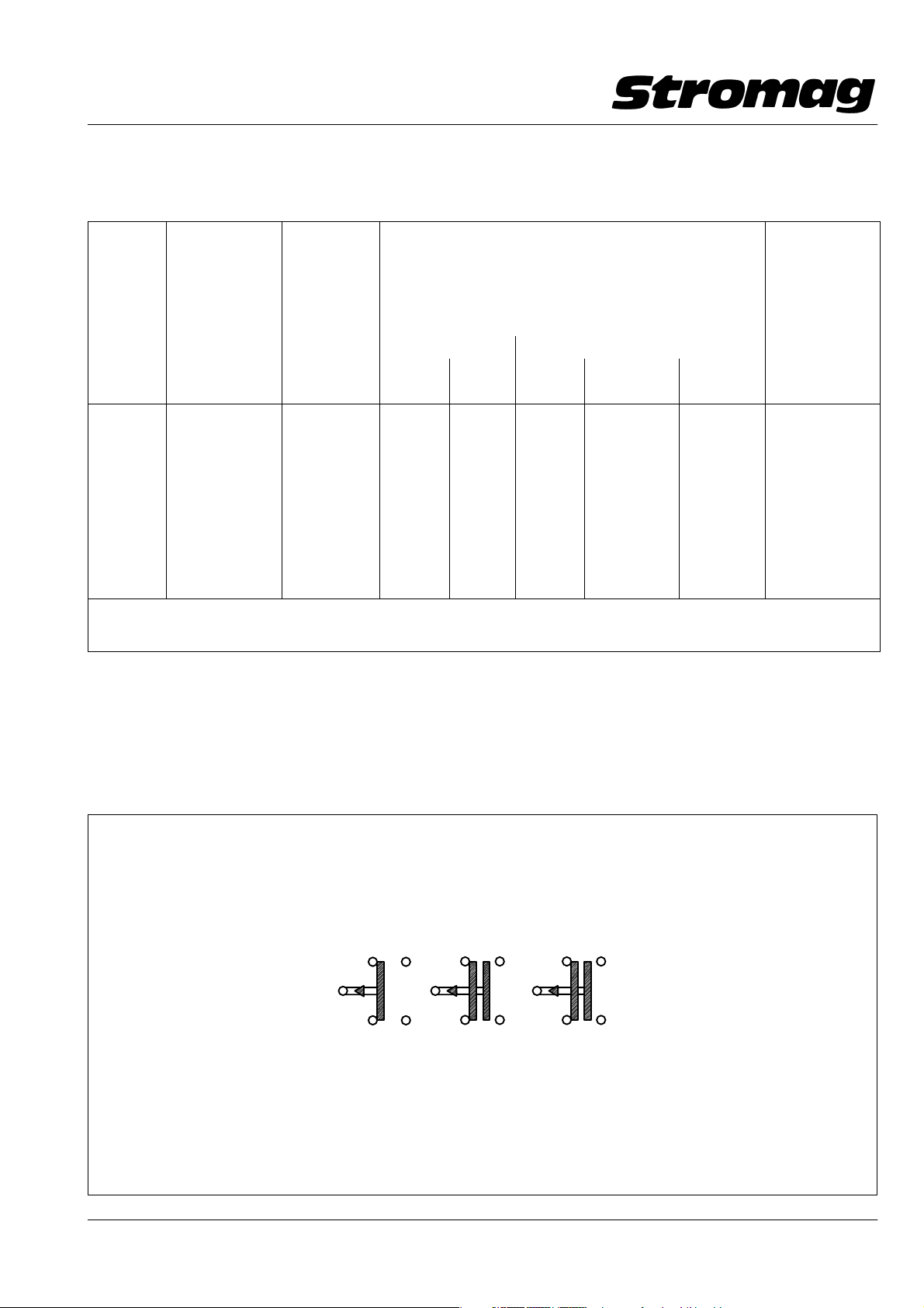
Störaussendungen sind nach Möglichkeit an der Stör−
quelle zu beseitigen.
Dazu nachfolgend prinzipielle Schutzbeschaltungen je
nach Art der vom Kontakt geschalteten Last.
Caution!
In every case the local safety and acci−
dent prevention regulations are also applicable, the
user must ensure that these are complied with.
We reserve the right to make modifications of a techni−
cal nature to this manual if required for limit switch deve−
lopment.
We recommend that these instructions are incorpora−
ted into the service manual of the user.
2.4 Electromagnetic compatibility
The user (system or machine manufacturer) has to as−
sure that the regulation for electromag − netic compati−
bility 89/336/EEC is adhered to, taking also into ac−
count the leaflet "EMC notes for operation and
mounting of electromagnetic clutches and brakes and
limit switches", No. 900 − 00001.
The leaflet is forwarded on request.
As far as possible, interferences have to be eliminated
at the source of interference.
See below principle protective wiring in relation to the
type of load operated by the contact.
Kontakt im Endschalter
Contact in the limit switch
geschaltete Last
switched load
Schutzbeschaltung
Protective wiring
Schütze
Contactors
Relaisspulen
Relay coils
Kupplungen/Bremsen
Clutches/brakes
Ventile
Valves
DD1_40268V
Datum / Date 07.2004
7
Page 9

Hebel − Endschalter / Lever Limit Switches
HHEV
Nr./No. 157 − 00000
3 Transport
3.1 Verpackung
Mitentscheidend für die Verpackunggsart ist der Trans−
portweg. Die auf der Verpackung angebrachten Bildzei−
chen sind zu beachten.
3.2 Zerlegungsgrad
Der Hebel − Endschalter wird komplett montiert gelie−
fert.
3.3 Empfindlichkeit
Beim Transport des Endschalters ist besonders vor−
sichtig zu verfahren, um Schäden durch Gewalteinwir−
kung oder unvorsichtiges Be − und Entladen zu verhin−
dern. Je nach Art und Dauer des Transportes sind
entsprechende Transportsicherungen vorgesehen.
Während des Transportes sind Kondenswasserbildung
auf Grund großer Tremperaturschwankungen sowie
Stöße zu vermeiden.
3.4 Zwischenlagerung
Bei der Zwischenlagerung ist wie beim Transport Kon−
denswasserbildung durch große Temperaturschwan−
kungen zu vermeiden. Eine Staubbildung sollte eben−
falls vermieden werden.
3.5 Lieferumfang
Der Inhalt der Verpackung ist auf der Packliste aufge−
führt, deren Vollständigkeit beim Empfang zu überprü−
fen ist. Eventuelle Transportschäden und /oder feh−
lende Teile sind sofort zu melden.
3 Transportation
3.1 Packing
The type of packing depends on the transportation
route and the delivery extent. The symbols marked on
the packing must be ad − hered to.
3.2 Pre − mounting condition
The lever limit switch is supplied completely mounted.
3.3 Sensitivity
Be particularly careful on transportation of the limit
switch in order to avoid damage due to external force
or careless loading and unloading. In relation to trans−
portation type and time, corresponding transportation
protection devices have to be provided. During trans−
portation avoid shocks as well as the generation of con−
densation water due to temperature fluctuations.
3.4 In − process stocking
In case of in − process stocking as well as during trans−
portation avoid the generation of condensation water
by strong temperature fluctuations. Also avoid the ge−
neration of dust.
3.5 Delivery extent
The content of the package is listed on the packing list.
On receipt check the completeness. Advise immedia−
tely any possible damage occured during transporta−
tion and/or any missing parts.
Datum / Date 07.2004
8
Page 10

Hebel − Endschalter / Lever Limit Switches
HHEV
Nr./No. 157 − 00000
4 Aufbau, Wirkungsweise, Konstruktionsmerkmale
(s. Bild 1)
Der Hebel − Endschalter besteht aus einem Hebel −
und Schalterteil, die fest miteinander verbunden sind.
Die Drehbewegung der Schaltwelle erfolgt formschlüs−
sig durch den Antriebshebel bis max. 85° nach jeder
Seite und wird mechanisch begrenzt. Wird der An−
triebshebel über 85° hinaus betätigt, so kommt es zu ei−
ner Zerstörung der Hebel − Rückholvorrichtung. Der
Hebel kann in 4 Positionen um je 90° an der Schaltwelle
montiert werden. Die Hebelbewegung wird gegen eine
Torsions − Schenkelfeder ausgeführt, die sich im Hebel−
teil befindet und wird von einem an der Stirnplatte be−
festigten Bolzen abgestützt. Der Bolzen und die Schen−
kelfeder mit dem Hebelteil gewährleisten, daß der
Antriebshebel und die Schaltwelle mit den Nocken−
scheiben nach Zurücknahme der Betätigungskraft in
die Mittelstellung zurückgehen.
Das Hebelteil ist so ausgebildet, daß es nach einer Dre−
hung von 85_ in beide Richtungen formschlüssig am
weiteren Drehen gehindert wird.
Die Schalterausführung "OA" wird ohne Hebel −
Rückholvorrichtung geliefert und hat keinen Anschlag.
Die Schaltwelle kann frei gedreht werden.
Die auf der Schaltwelle befestigten Nockenscheiben
zur Betätigung der Kontakte können stufenlos und un−
abhängig voneinander verstellt werden.
Entsprechend der gewünschten Kontaktanordnung
können Nockenscheiben mit 40° oder 180° Nocken se−
rienmäßig, und alle anderen Gradzahlen als Sonder−
ausrüstung eingebaut sein. Einstellungsarten siehe
Bild 2 − 5.
Das Aluminium − Gehäuse entspricht der Schutzart
IP65 nach DIN VDE 0470 − 1 / EN 60529.
Der Antriebshebel ist serienmäßig mit einer gleitgela−
gerte MS − Rolle ausgerüstet. Als Sonderausrüstung
kann eine kugelgelagerte 80 mm breite Walze aus
Kunststoff eingebaut werden.
4 Construction, functioning, constructional charac−
teristics (see Fig. 1)
The lever limit switch consists of a lever part and a
switch part which are connected rigidly to each other.
The motion of rotation of the switching shaft is made po−
sitively through the drive (input) lever up to max. 85° in
each direction; it is limited mechanically. When the drive
lever is actuated exceeding 85°, the lever return motion
device is destroyed. The lever can be mounted at the
switching shaft in 4 positions by 90° each. The lever mo−
tion is carried − out against 2 tension springs which are
included in the lever part and which draw a left and a
right limiting lever each against a center stop, thus as−
suring that the drive (input) lever and the switching shaft
with the cam discs are returned into center position after
cancellation of the actuaction force.
The lever part is designed in such a way that after a rota−
tion of 85_ in both direction it is form − fit prevented from
any further rotation.
The switch execution "OA" is supplied without lever re−
turn motion device and has no limit stop.
The switching shaft can be rotated freely.
The cam discs, which are fixed onto the switching shaft
to actuate the contacts, can be adjusted infinitely and
independently from each other.
In relation to the required contact arrangement, the cam
discs can be fitted with 40° or 180° cams (standard ex−
ecution) or with other degrees as special execution. Ty−
pes of setting as per fig. 2 to 5.
The aluminium housing complies with protection IP65
to DIN VDE 0470 − 1 / EN 60529.
As standard, the drive lever is equipped with a glide −
bearinged plastic roller. As special execution, a sealed
grooved ball bearing or a ball bearinged roller, 80 mm
wide, of synthetic material, can be fitted.
Datum / Date 07.2004
9
Page 11

Hebel − Endschalter / Lever Limit Switches
HHEV
Nr./No. 157 − 00000
Bild/Fig. 1
DD1 − 40408H
Datum / Date 07.2004
10
Page 12

Hebel − Endschalter / Lever Limit Switches
HHEV
Nr./No. 157 − 00000
5 Einbau des Hebel − Endschalters
Achtung!
Der Endschalter darf nur von autori−
siertem, ausgebildetem und eingewiesenem Perso−
nal bedient, gewartet und instandgesetzt werden.
Dieses Personal muß die komplette BA gelesen, ver−
standen und eine spezielle Unterweisung über auf−
tretende Gefahren erhalten haben.
Die Einbaulage des Hebel − Endschalters ist beliebig.
Im Normalfall wird der Endschalter in der Bauform B3,
d.h. mit Fußbefestigung, geliefert. Die Hebelstellung
zum Befestigungsfuß des Endschalters ist 4 mal um 90°
verstellbar. Die Hebelrolle sollte mit einem Betäti−
gungselement mit ca. 30° Auflaufschräge betätigt wer−
den. Wird der Antriebshebel um mehr als 85° betätigt,
erfolgt eine mechanische Zerstörung des Hebelmecha−
nismus.
Nach der Verdrahtung und vor der Schaltpunkteinstel−
lung muß jeder Kontakt mit einem Berührungsschutz
ausgerüstet sein. Sofort nach der Schaltpunkteinstel−
lung muß der Kontaktraum wieder mit der Haube
verschlossen werden, damit kein eindringender Staub
oder Wasser die Abschaltsicherheit beeinträchtigen
kann.
Ebenso werden dadurch Unfälle durch Berührung
spannungsführender Teile verhindert.
Beim Aufsetzen der Haube ist auf vollzähliges und
gleichmäßiges Anziehen der Schrauben zu achten, da−
mit ein Verkanten der Haube und eine schlechte An−
pressung der Dichtung vermieden wird.
Die verwendeten Kabel − Verschraubungen müssen
der Schutzart IP68 entsprechen. Bei der Kabelmontage
ist besonders darauf zu achten, daß die Klemm − Mutter
nach der Einführung des Kabels sorgfältig angezogen
wird. Das Anzugsmoment soll, je nach Kabelart, zwi−
schen 2 und 3 Nm liegen. Da sich der Kunststoffmantel
bei einigen Kabeln an der Klemmstelle in der Kabel −
Verschraubung durch die Einschnürung bleibend ver−
formt, ist es ratsam, die Klemm − Mutter nach 3 − 4 Ta−
gen um eine halbe Umdrehung nachzuziehen.
Die Kabelführung zum Endschalter soll so ausgeführt
sein, daß das Kabel kein Wasser an die Kabel − Ver−
schraubung leiten kann.
5 Assembly of the lever limit switch
Caution!
Every person involved in operating,
maintaining and repairing the limit switch must be
authorized, adequately trained and instructed. Each
such person must have read and understood this in−
struction manual and must have been instructed in
particular in relation to possible danger.
Mounting position of the lever limit switch as required.
Normally the limit switch is supplied in form B3, i.e. with
foot fastening (pedestal). The lever position to the fixing
foot of the limit switch can be adjusted 4 times by 90°.
The lever roller should be actuated by an actuation ele−
ment with approx. 30° stopping pitch. When the drive
lever is actuated by more than 85°, the lever mecha−
nism is mechanically destroyed.
After wiring and before the switching point adjustment,
each contact has to be equipped with a protection
against accidental touch. After adjustment of the swit−
ching point, the contact space must immediately be
re − locked by the cap in order to prevent penetrating
dust or water from affecting the switching − off safety.
Thereby accidents by touching live parts are avoided,
too.
When fitting the cap pay attention that all screws are
tightened uniformly in order to avoid tilting of the cap
and a bad pressuring of the sealing.
The used cable glands must comply with protection IP
68. When fitting the cable pay particular attention that
after insertion of the cable the tightening nut is carefully
tightened. The wrench torque shall be between 2 and
3 Nm relative to the type of cable. As a permanent defor−
mation of the plastic sheat of some cables can occur at
the contact point in the cable gland because of contrac−
tion, it is recommended to re − tighten the tightening nut
by 1/2 revolution after 3 to 4 days.
The cable conduct to the limit switch shall always be ex−
ecuted to prevent the cable from conducting water to
the cable gland.
Datum / Date 07.2004
11
Page 13

Hebel − Endschalter / Lever Limit Switches
HHEV
Nr./No. 157 − 00000
6 Inbetriebnahme
6.1 Kontakt − Einstellung
!
Zur Kontakteinstellung ist die Haube des
Endschalters zu entfernen. Vor der Schaltpunktein−
stellung ist sicherzustellen, daß die spannungsfüh−
renden Kontaktanschlüsse durch einen Berüh−
rungsschutz abgedeckt sind und es zu keiner
Berührung der Anschlüsse kommen kann.
6.1.1 Normaleinstellung "V50" (s. Bild 2)
Jedem Kontakt sind zwei Nockenscheiben zugeordnet,
die stufenlos verstellbar sind.
Die Nockenscheiben (1) lassen sich nach Lösen der
Mutter (3) unabhängig voneinander verstellen. Das Si−
cherungsblech (2) verhindert dabei, daß sich eine vor−
her eingestellte Nockenscheibe durch die Einstellung
der nachfolgenden Scheibe verstellt.
An der 30° − Stricheinteilung der Nockenscheibe (1)
läßt sich in Verbindung mit der Zeigerspitze (4) des Si−
cherheitsbleches (2) eine Grobeinstellung durchfüh−
ren. Nach dem Einstellen der Schaltpunkte muß die
Mutter (3) mit einem Anzugsmoment von 2,5 Nm ange−
zogen werden.
Die Nockenscheiben sind so ausgebildet, daß jeweils
ein konstanter Nutz − und Nachlaufweg zur Verfügung
steht. Entsprechend der Stellung der Nocken für einen
Kontakt kann der Nachlaufweg verdoppelt und der
Nutzweg entsprechend verkürzt werden (siehe
Kap.9.1).
Bei Überschreiten des Nachlaufweges tritt keine Be−
schädigung ein. Es erfolgt jedoch wieder eine Öffnung
oder Schließung des Kontaktes.
6 Commissioning
6.1 Contact adjustment
!
To adjust the contacts, remove the cap of
the limit switch. Before adjusting the switching point
assure that the live contact connections are covered
by a protection against accidental touch and that
touching of the connections is excluded.
6.1.1 Normal adjustment "V50" (see Fig. 2)
Two infinitely adjustable cam discs are provided for
each contact.
After loosening of the nut (3), the cam discs (1) can be
set independently from each other. The safety plate (2)
prevents a previously adjusted cam disc from changing
because of the adjustment of the subsequent disc.
At the 30° graduation of the cam disc (1) a rough adjust−
ment can be made in connection with the point of index
(4) of the safety plate (2). After adjustment of the swit−
ching points, the nut (3) must be tightened by a wrench
torque of 2.5 Nm.
The cam discs are designed to dispose of a constant
useful travel and constant overtravel. In relation to the
position of the cams for one contact, the overtravel can
be doubled and the useful travel can be reduced accor−
dingly (see chapter 9.1).
When exceeding the overtravel, the switch is not dama−
ged. The contact, however, is opened or closed again.
Bild/Fig. 2
DD1_40345H
Datum / Date 07.2004
12
Page 14

Hebel − Endschalter / Lever Limit Switches
HHEV
Nr./No. 157 − 00000
6.1.2 Feineinstellung "FV50" (s. Bild 3)
Jedem Kontakt ist eine Nockenscheibengruppe, beste−
hend aus Stellnocken (6) und Nockenscheibe (7), zu−
geordnet. Der Stellnocken (6) ist über einen Ring mit
beidseitiger Verzahnung (2) formschlüssig mit der
Schaltwelle verbunden. Mit der in Selbsthemmung be−
findlichen Schnecke (8) wird das Drehmoment weiter
formschlüssig vom Stellnocken (6) auf die Verzahnung
der Nockenscheibe (7) übertragen.
Die Nockenscheibe (7) kann durch Drehen der Schnek−
ke (8) im Verhältnis 74:1 (1 Umdrehung der Schnecke
= 4,865° an der Nockenscheibe) in Umfangsrichtung
verstellt werden. Mit einem Schraubendreher, max. 4
mm breit, ist eine äußerst feine Einstellung von beiden
Seiten her möglich, ohne daß die Mutter (3) gelöst wer−
den muß.
Um die Schnecke (8) in eine bestimmte Stellung zu brin−
gen oder um eine Grob − Voreinstellung durchzuführen,
muß die Mutter (3) so weit gelöst werden, daß jeweils
für einen Stellnocken die stirnseitige Verzahnung außer
Eingriff kommt. Dann kann die Verstellung erfolgen, oh−
ne daß die anderen Nockenscheibengruppen sich mit
verstellen. Nach dieser Voreinstellung muß die Mutter
(3) mit einem Anzugsmoment von 2,5 Nm angezogen
werden.
Die Nockenscheiben sind so ausgebildet, daß jeweils
ein konstanter Nutz − und Nachlaufweg zur Verfügung
steht. Bei Überschreitung des Nachlaufweges tritt keine
Beschädigung des Schalters ein. Es erfolgt jedoch wie−
der eine Öffnung oder Schließung des Kontaktes (siehe
Kap. 9.1).
6.1.2 Precise adjustment "FV50" (see Fig. 3)
A cam disc group consisting of adjusting cam (6) and
cam disc (7) is provided for each contact. The adjusting
cam (6) is positively connected to the switching shaft by
means of a ring with toothing on both sides (2). By the
self − locked worm (8) the torque is positively transmit−
ted from the adjusting cam (6) to the toothing of the cam
disc (7).
By turning the worm (8) in the ratio 74:1 (1 revolution of
the worm = 4.865° at the cam disc) the cam disc (7) can
be adjusted in circumferential direction. A very precise
adjustment from both sides is possible by means of a
screw driver, max. 4 mm wide, without having to loosen
the nut (3).
To set the worm (8) into a defined position or to carry −
out a rough pre − setting, loosen the nut (3) so far that
for one adjusting cam each, the front − side toothing is
not catching. Then the setting can be made without any
adjustment of the other cam disc groups. After that
pre − setting, the nut (3) must be tightened by a wrench
torque of 2.5 Nm.
The cam discs are designed to dispose of a constant
useful travel and a constant overtravel. When excee−
ding the overtravel, the switch is not damaged. The con−
tact, however, is opened or closed again (see chapter
9.1).
Bild/Fig. 3
Datum / Date 07.2004
Ansicht / View yAnsicht / View yAnsicht / View yAnsicht / View yAnsicht / View y
Ansicht / View x
DD1_40346H
13
Page 15

Hebel − Endschalter / Lever Limit Switches
HHEV
Nr./No. 157 − 00000
6.1.3 Doppel − Feineinstellung "DFV"
(s. Bild 4)
Jedem Kontakt sind zwei Nockenscheibengruppen,
bestehend aus Stellnocken (6) und Nockenscheiben
(7), zugeordnet.
Die Einstellung der einzelnen Nockenscheiben ist im
Kap. 6.1.2 beschrieben.
Der Anwender von dieser DFV − Einstellung hat den
Vorteil, daß das stufenlos einstellbare Nockenschei−
benpaar von beiden Seiten definiert benutzt werden
kann.
View y
6.1.3 Double precision adjustment "DFV"
(see Fig. 4)
Two cam disc assys comprising adjusting cams (6) and
cam discs (7) are assigned to each contact.
The adjustment of the single cam discs is described in
chap. 6.1.2.
The user of this DFV − adjustment disposes of the ad−
vantage that the infinitely adjustable cam disc pair can
be used in a defined way from both sides.
View x
Bild / Fig. 4
DD140726H
14
Datum / Date 07.2004
Page 16

Hebel − Endschalter / Lever Limit Switches
HHEV
Nr./No. 157 − 00000
6.1.4 Normaleinstellung "V70" (s. Bild 5)
Jedem Kontakt sind zwei Nockenscheiben zugeordnet,
die stufenlos verstellbar sind.
Die Nockenscheiben (1) lassen sich nach Lösen der
Mutter (3) unabhängig voneinander verstellen. Das Si−
cherungsblech (2) sowie der Innenring (4) verhindern
dabei, daß sich eine vorher eingestellte Nockenscheibe
durch die Einstellung der nachfolgenden Scheibe ver−
stellt.
Nach dem Einstellen der Schaltpunkte muß die Mutter
(3) mit einem Anzugsmoment von 2,5 Nm angezogen
werden.
Die Nockenscheiben sind so ausgebildet, daß jeweils
ein konstanter Nutz − und Nachlaufweg zur Verfügung
steht. Entsprechend der Stellung der Nocken für einen
Kontakt kann der Nachlaufweg verdoppelt und der
Nutzweg entsprechend verkürzt werden.
Bei Überschreiten des Nachlaufweges tritt keine Be−
schädigung ein. Es erfolgt jedoch wieder eine Öffnung
oder Schließung des Kontaktes.
6.1.4 Normal adjustment "V70" (see Fig. 5)
Two infinitely adjustable cam discs are provided for
each contact.
After loosening of the nut (3), the cam discs (1) can be
set independently from each other. The safety plate (2)
prevents a previously adjusted cam disc from changing
because of the adjustment of the subsequent disc.
After adjustment of the switching points, the nut (3)
must be tightened by a wrench torque of 2.5 Nm.
The cam discs are designed to dispose of a constant
useful travel and constant overtravel. In relation to the
position of the cams for one contact, the overtravel can
be doubled and the useful travel can be reduced accor−
dingly.
When exceeding the overtravel, the switch is not dama−
ged. The contact, however, is opened or closed again.
Bild/Fig. 5
Wirksamer Nockenwinkel
Effective cam angle
Nutzbarer Winkel der Nockenscheibe
Useful angle of the cam disc
1342
DD1 40317V
Datum / Date 07.2004
15
Page 17

Hebel − Endschalter / Lever Limit Switches
HHEV
Nr./No. 157 − 00000
6.1.5 Feineinstellung "FV70" (s. Bild 6)
Jedem Kontakt ist eine Nockenscheibengruppe, beste−
hend aus Nockenscheibe (1), Stellnocken (2), Verstell−
schnecke (3) und Zahnring (4) zugeordnet. Der Stell−
nocken (2) ist über den Zahnring (4) formschlüssig mit
der Schaltwelle verbunden. Mit der in Selbsthemmung
befindlichen Verstellschnecke (3) wird das Drehmo−
ment weiter formschlüssig vom Stellnocken (2) auf die
Verzahnung der Nockenscheibe (1) übertragen.
Die Nockenscheibe (1) kann durch Drehen der Verstell−
schnecke (3) im Verhältnis 108:1 (1 Umdrehung der
Schnecke = 3.333° an der Nockenscheibe) in Um−
fangsrichtung verstellt werden. Mit einem Schrauben−
dreher, max. 4 mm breit, ist eine äußerst feine Einstel−
lung von beiden Seiten her möglich, ohne daß die
Mutter (5) gelöst werden muß.
Um die Verstellschnecke (3) in eine bestimmte Stellung
zu bringen oder um eine Grob − Voreinstellung durch−
zuführen, muß die Mutter (5) so weit gelöst werden, daß
jeweils für einen Stellnocken die stirnseitige Hirth − Ver−
zahnung (6) zwischen Stellnocken (2) und Zahnring (4)
außer Eingriff kommt. Dann kann die Verstellung erfol−
gen, ohne daß die anderen Nockenscheibengruppen
sich mit verstellen. Nach dieser Voreinstellung muß die
Mutter (5) mit einem Anzugsmoment von 2,5 Nm ange−
zogen werden.
Die Nockenscheiben sind so ausgebildet, daß jeweils
ein konstanter Nutz − und Nachlaufweg zur Verfügung
steht. Bei Überschreitung des Nachlaufweges tritt keine
Beschädigung des Schalters ein. Es erfolgt jedoch wie−
der eine Öffnung oder Schließung des Kontaktes (siehe
Kap. 9.1).
6.1.5 Precise adjustment "FV70" (see Fig. 6)
A cam disc group consisting of cam disc (1), adjusting
cam (2), adjusting worm (3) and toothed ring (4) is pro−
vided for each contact. The adjusting cam (2) is positi−
vely connected to the switching shaft by means of a too−
thed ring (4). By the self − locked worm (3) the torque is
positively transmitted from the adjusting cam (2) to the
toothing of the cam disc (1).
By turning the worm (3) in the ratio 108:1 (1 revolution
of the worm = 3.333° at the cam disc) the cam disc (1)
can be adjusted in circumferential direction. A very pre−
cise adjustment from both sides is possible by means
of a screw driver, max. 4 mm wide, without having to loo−
sen the nut (5).
To set the worm (3) into a defined position or to carry −
out a rough pre − setting, loosen the nut (5) so far that
for one adjusting cam each, the front − side Hirth too−
thing (6) between adjusting cam (2) and toothed ring (4)
is not catching. Then the setting can be made without
any adjustment of the other cam disc groups. After that
pre − setting, the nut (5) must be tightened by a wrench
torque of 2.5 Nm.
The cam discs are designed to dispose of a constant
useful travel and a constant overtravel. When excee−
ding the overtravel, the switch is not damaged. The con−
tact, however, is opened or closed again (see chapter
9.1).
Bild/Fig. 6
DD1 40318H
Datum / Date 07.2004
16
Page 18

Hebel − Endschalter / Lever Limit Switches
HHEV
Nr./No. 157 − 00000
7 Betrieb
!
Unabhängig von nachfolgenden Hinwei−
sen gelten für den Betrieb des Endschalters in je−
dem Falle die am Einsatzort gesetzlich vorgeschrie−
benen Sicherheits − und Unfallverhütungsvor −
schriften. Der Anwender hat für die Einhaltung die−
ser Vorschriften zu sorgen.
7.1 Betriebsbedingungen
Die Betriebsbedingungen, die für einen störungsfreien
Betrieb einzuhalten sind, werden nachfolgend aufge−
führt:
Die Umgebungstemperatur für den Endschalter darf
− 40°C bis +85°C betragen.
Bei Verwendung der Kontakte 51,52 und 53 darf die Mi−
nustemperatur max. − 30°C betragen.
7.2 Schutzarten
Der Endschalter wird in der Schutzart IP 65 nach EN
60529 geliefert.
7 Operation
!
Independent from the following hints, the
legal safety prescriptions for prevention of accident
prescribed for the particular application case apply
to the operation of this limit switch. The user is held
responsible to adhere to these prescriptions.
7.1 Service conditions
The service conditions to be adhered to in order to en−
sure a faultless operation of the limit switch, are listed
below:
The ambient temperature must not exceed 85°C and
must not fall below − 40°C.
When using the contacts 51, 52 and 53, the minus tem−
perature may be max. − 30°.
7.2 Types of protection
The limit switch is supplied with protection IP 65 as per
EN 60529.
8 Instandhaltung
Bei Wartungs − und Inspektionsarbeiten ist das Kapitel
2 "Sicherheitshinweise" zu beachten.
Grundsätzlich sind keine Wartungs − oder Inspektions−
arbeiten am Endschalter erforderlich.
Staubablagerungen auf den Kontakten oder im Kon −
taktraum dürfen auf keinen Fall mit Preßluft entfernt wer−
den, da der Staub dadurch erst recht in die Kontakte
eindringen und das Schaltvermögem beeinträchtigen
kann.
Achtung!
des Endschalters Benzin verwendet werden. Die
Haubendichtung ist nach dem Öffnen der Haube
nach längere Betriebszeit zu erneuern.
Auf keinen Fall darf für die Reinigung
8 Maintenance
When carrying − out maintenance and inspection
works, pay attention to chap. 2 "Safety guide − lines".
Generally no maintenance or inspection works at the
geared limit switch are necessary.
Do not remove dust deposits on the contacts or in the
contact space by means of compressed air. The dust
would penetrate into the contacts and would affect the
switching capacity.
Caution!
limit switch. The cap sealing has to be replaced after
having opened the cap after a longer period of ope−
ration.
Do not use benzine for cleaning of the
Datum / Date 07.2004
17
Page 19

Hebel − Endschalter / Lever Limit Switches
HHEV
Nr./No. 157 − 00000
9 Ausführung mit Heizwiderstand
Zur Vermeidung von Kondenswasser im Schalterraum
kann ein Heizwiderstand eingebaut werden. Diese Hei−
zung ist so ausgelegt, daß eine Heizleistung je nach
Spannung von ca. 2,5 Watt bzw. 4 Watt zur Verfügung
steht (entsprechende Versorgungsspannung 12 − 36 V
AC/DC oder 110 − 250 V AC/DC nach Bestellung). Die
PTC − Heizung ist selbstregelnd und temperaturbe−
grenzend und führt somit zu einer selbsttätigen Anpas−
sung an die Umgebungstemperatur. Der Anschluß er−
folgt über eine 2polige Klemmleiste.
Der Heizwiderstand und die Klemmleiste werden seit−
lich am Kontaktträger mit 3 Stück M3 − Schrauben und
Muttern befestigt, s. Bild 7.
!
Die Oberfläche der Heizung kann sich auf
ca. 60_C erwärmen.
Getriebeseite / Gear side
9 Execution with heating resistor
To avoid the generation of condensation water in the
switch space, a heating resistor can be fitted. This hea−
ting is designed to dispose of a heating output of ap−
prox. 2.5 watts or 4 watts (corresponding supply vol−
tage 12 − 36 volts a.c./d.c. or 110 − 250 volts a.c./d.c.(as
per order). The PTC − heating is self − regulating and
temperature − limiting thus resulting in an automatic
adaptation to the ambient temperature. The connection
is made through a two − pole terminal strip.
The heating resistor and the terminal strip are fixed late−
rally to the contact supports by means of 3 pcs. screws
M3 and nuts; see Fig.7.
!
The surface of the heating can reach a tem−
perature of approx. 60_C.
Ausführung/Execution: UB12 − 36V AC/DC 110 − 250V AC/DC
Heizleistung/Heating cap.: ca. 2.5 Watt ca. 4 Watt
(im ausgeregelten Zustand/in levelled condition)
Kaltwiderstand PTC (bei/at 25_C)
Cold resistance PTC: R25 20 ± 35% R25 1500 ± 35%
PTC − Bezugstemperatur:
PTC ref. temperature: 50_C50_C
Schutzklasse
Protection
Anschlußleitung: 2x0.25mm2, Silikonkabel 2x0.25mm2, Silikonkabel
Connection cable: 2x0.25mm
Heizkörper/Radiator: Aluminium eloxiert/eloxed Aluminium eloxiert/eloxed
Bild/Fig. 7
(VDE 0100, 0160):II II
2
, Siliconecable 2x0.25mm2, Siliconecable
18
Ersatzschaltbild
Equivalent wiring dia.
12
U
*
B
PTC
*Anschlußspannung je nach
verwendeter Variante
Connection voltage in
relation to the variant used
12 − 36V AC/DC
bzw./or
110 − 250V AC/DC
Datum / Date 07.2004
DD1 − 40298V
DD1 40186H
Page 20

Hebel − Endschalter / Lever Limit Switches
HHEV
Nr./No. 157 − 00000
10 Ersatzteilhaltung und Kundendienst
10.1 Ersatzteilhaltung
Der Endschalter ist so konstruiert, daß es keine Teile mit
besonders hohem Verschleißverhalten unter den Ein−
satzbedingungen gem. Kap. 7.1 gibt.
Der Endschalter ist so konstruiert, daß er bei Einhaltung
der Betriebsbedingungen gem. Kap. 7.1 eine hohe Le−
bensdauer erzielt.
Sollte es wider erwarten doch einmal erforderlich sein,
ein Teil gegen ein neues Teil zu ersetzen, so kann dieses
mittels einer Ersatzteilliste identifiziert werden. Die Er−
satzteilliste kann von unserem technischen Kunden−
dienst angefordert werden (Anschrift siehe Kap. 10.3).
Aus Sicherheitsgründen empfehlen wir jedoch den
kompletten Schalter zur Reparatur an uns zu senden.
10.2 Daten für die Ersatzteilbestellung und Rückfra−
gen
Zur Ersatzteilbestellung bedienen Sie sich bitte der an−
zufordernden Ersatzteilliste.
Es sind folgende Angaben erforderlich:
Auftrags − Nr. s. Kap. 1.1
Baureihe u. Größe s. Kap. 1.1
Typ s. Kap. 1.1
Position und Benennung
s. Ersatzteilliste
des Ersatzteiles
Stückzahl
Order − Ref. − No. see chap. 1.1
Series and Size see chap. 1.1
Type see chap. 1.1
Item − number and designa −
tion of the spare part
see spare
parts list
Quantity
Errichten von Starkstromanlagen mit Nennspannungen bis 1000 V
Erection of power installations with nominal voltages up to 1000 volts
IEC 60364 − 4 − 41
IEC 60364 − 1
Niederspannug − Schaltgeräte / Low − voltage switching devices EN 60947 − 5 − 1
Schutzarten durch Gehäuse / Protections by housing EN 60529
Datum / Date 07.2004
19
 Loading...