

STROETER SC 750/5, SC3-2200/5, SC3-1100/5, SC3-4000/5, SC 1500/5 User Manual
...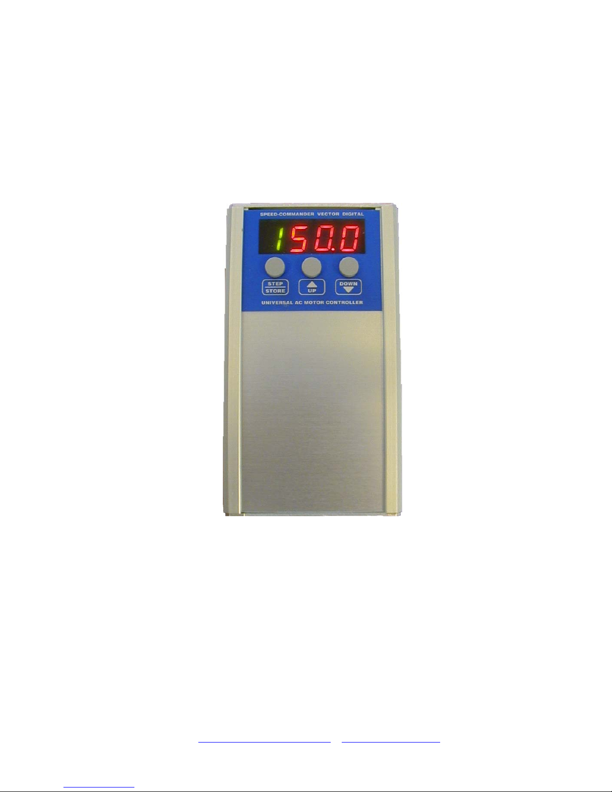
SPEED-Commander
Universal frequency inverter
Standard user guide
Version 5.x.x
Universal AC-Motor-Controller
With integrated:
• Speed control
• PI-regulation
• Positioning
• Synchronous Control
• Torque limiting
STRÖTER Antriebstechnik GmbH
40549 Düsseldorf . Krefelder Straße 117 . Telefon: 0211/95600-0
40522 Düsseldorf . Postfach 19 03 27 . Fax: 0211/504415
http://www.stroeter.com/
- info@stroeter.com

Standard user guide
V51-00-V19 eng
-2- Rights to changes reserved
The Speed Commander
Frequency inverter are used
to control the speed of a 3
phased ac motor.
This generation of the Speed
Commander is developed to
be used in all sorts of
industrial applications. The
Speed Commanderen is a
UNIVERSAL AC MOTOR
CONTROLLER; it contains a
lot of other special programs
besides the ordinary speed
controlling. These special
programs can be used for
simple as well as advanced
applications as pressure
regulation, serial
communication, time
controlling, torque control
and many more.
The buttons and the display
on the Speed Commander set
up the special programs.
This manual covers the
complete product line from
0,75Kw to 22Kw.
Manuals for special program
must be ordered separately.
It is very important that this
manual is read before
connecting the controller
because of:
• Personal safety
• Product lifetime
• Reliability
• Optimum
performance.
SPEED-COMMANDER
Index:
1
Introduction......................................................................................................3
1.1 Generally....................................................................................................3
1.2 Properties / advantages ..............................................................................3
1.3 CE-Approval..............................................................................................4
1.4 Technical specifications.............................................................................4
1.5 Power and torque curves............................................................................6
2 Installation........................................................................................................7
2.1 Generally....................................................................................................7
2.2 Mounting and installation ..........................................................................7
2.3 Decision of motor direction .......................................................................8
2.4 Decision of the counter direction (When using encoder)...........................8
2.5 Parameter setting........................................................................................9
2.6 Parameter table – Standard frequency inverter (program 0) ....................10
2.7 Notes to parameters .................................................................................11
2.8 Information about positions tolerance and hysteresis (PAR. U and Y) ...17
2.9 Error codes...............................................................................................18
2.10 Mains supply............................................................................................19
2.11 Control inputs ..........................................................................................20
2.12 Emissions and immunity..........................................................................22
2.13 Connection samples for program 0 ..........................................................23
2.14 Connection of brake motor and resistor...................................................24
3 Actual settings................................................................................................25

Standard user guide
V51-00-V19 eng
-3- Rights to changes reserved
1 Introduction
1.1 Generally
The Speed Commander V5 is a static frequency inverter with DC-link voltage for
continuously variable speed control of AC motors.
• Vector modulation and 16bit microprocessor
• Display for
- Motor frequency, current, DC link voltage, parameters, error codes, positions and more.
• Galvanic separated control inputs for:
- Motor frequency, Motor voltage (torque)
- Right rotation
- Left rotation
- STOP (Brake function)
- OFF (Powerless motor wires)
- STOP (DC-Braking)
• Programmable relay and NPN outputs.
• Special V/F curves for ventilation and pump operation.
• Power range from 0,75 kW - 1x230 VAC / to 22 kW - 3x400 VAC
• Integrated software programs for:
- PI-regulation (Pressure , temperature etc.)
- Positioning
- Digital synchronous drive
- Torque limiting / Supervision
• Serial communication with PC or PLC
• Special software with custom designed PLC functions.
• Possibility to upgrade internal software by serial RS232 connection to PC (SpeedUp).
1.2 Properties / advantages
• Danish developed hard and software
• Flexible and future safe software development of the controller board
• Simple control of parameters by digital parameter setting.
• High start torque (170%)
• Soundless motor drive by high pulse frequency and vector modulation.
• IxR- compensation (Boost)
• Programmable voltage / frequency relation.
• DC-braking
• Over/under voltage protection. Overload protection.
• Small dimensions.
• Possibility to drive multiple motors.
• Options:
- Serial communication RS232 / RS485
- Brake-Chopper and brake resistor
- External display
- SpeedUp Windows program for updating the internal software.
Standard user guide
V51-00-V19 eng
-4- Rights to changes reserved
1.3 CE-Approval
The SPEED-COMMANDER frequency inverter is designed to be build-in machinery systems. To meet
the demands for low-tension directive 73/23/EEG and the EMC-directive 89/336/EEC, must the
directions for setup and Correct EMC installation be meet. The frequency inverter are designed after
following standards:
EN 60204-1
Safety of machine systems – Electrical machine gear
EN 60146-1-1
Semiconductor inverter – Generally demands for mains powered inverters
EN 50081-1
Standards for emission
EN 50082-2
Standards for immunity (Industrial area)
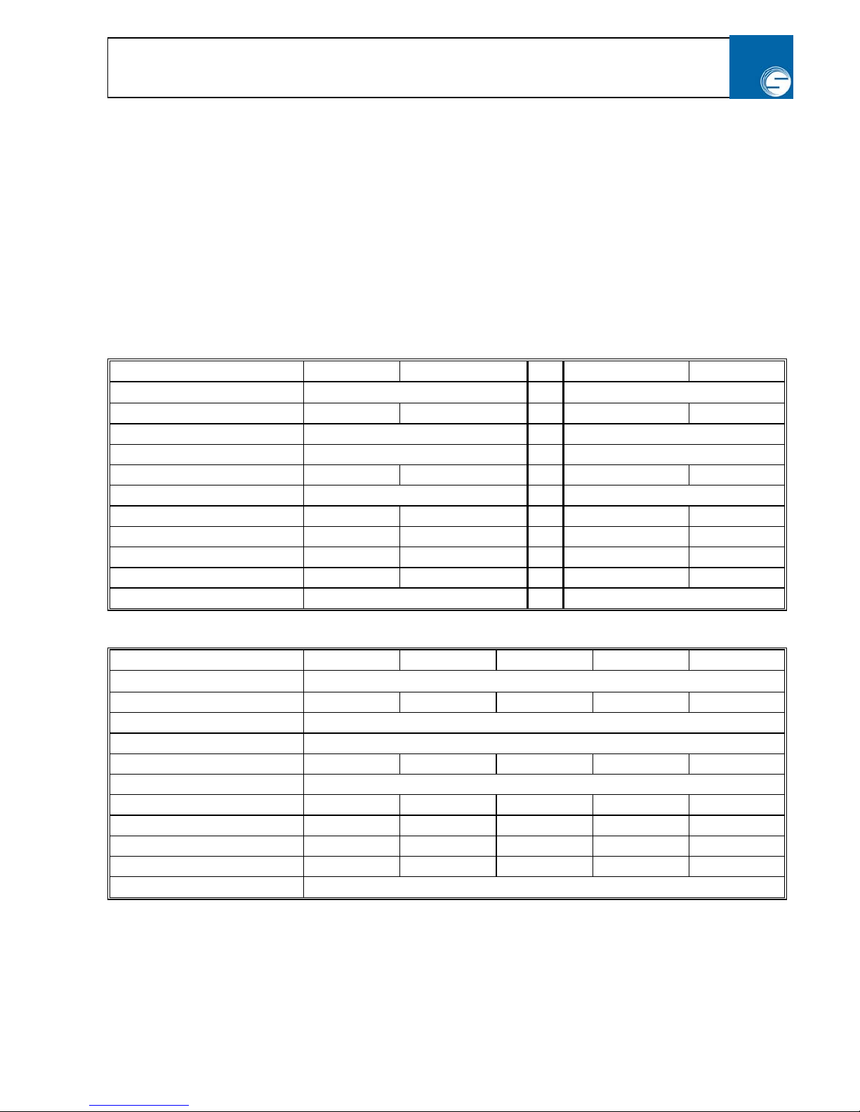
1.4 Technical specifications
Type: SC 750/5 SC 1500/5 SC3-1100/5 SC3-2200/5
Mains supply:
230 V ± 10% / 50 - 60 Hz
3 x 400 V ± 10% / 50 - 60 Hz
Max. Motor load: 0,75 kW 1,5 kW 1,1 kW 2,2 kW
Output voltage: 3 x 0 - 230 V 3 x 0 - 400 V
Output frequency: 0 - 400 Hz 0 - 400 Hz
Nominal current: 3 x 4 A 3 x 7 A 3 x 3,6 A 3 x 5,5 A
Overload: 150% in 30 sec. 150% in 30 sec.
Max. current limit (TRIP) 3 x 7,6 A 3 x 14 A 3 x 6,8 A 3 x 10,5 A
Input current About 8 A About 15 A About 3 x 4 A About 3 x 5 A
Recommended mains fuse: 16 A 20 A 3 x 10 A 3 x10 A
Max heat loss 50 W 100 W 80 W 160 W
Capsulation: IP 20 IP 20
Type: SC3-4000/5 SC3-5500/5 SC3-7500/5 SC3-11000/5 SC3-22000/5
Mains supply:
3 x 400 V ± 10% / 50 - 60 Hz
Max. Motor load: 4,0 kW 5,5 kW 7,5 kW 11 kW 22 kW
Output voltage: 3 x 0 - 400 V
Output frequency: 0 - 400 Hz
Nominal current: 3 x 9,5 A 3 x 13 A 3 x 18 A 3 x 24 A 3 x 44 A
Overload: 150% in 30 sec.
Max. current limit (TRIP) 3 x 18 A 3 x 25 A 3 x 34 A 3 x 45 A 3 x 66 A
Input current 3 x 10 A 3 x 14 A x 20 A 3 x 28 A 3 x 45 A
Recommended mains fuse: 3 x 10 A 3 x 16 A 3 x 20 A 3 x 35 A 3 x 50 A
Max heat loss 250 W 350 W 400 W 500 W 1000 W
Capsulation: IP 20
Standard user guide
V51-00-V19 eng
-5- Rights to changes reserved
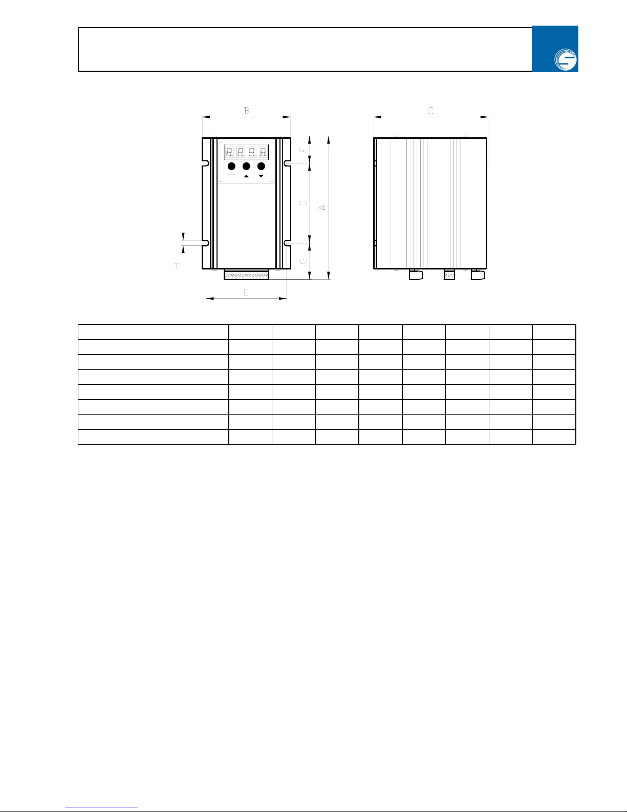
Mechanical measures:
Type:
A B C D E F G H
SC-750/5
163 104 133 90 96 30 43 6
SC-1500/5 and SC3-2200/8
298 104 133 140 96 86 72 6
SC3-1100/5
268 104 133 140 96 56 72 6
SC3-4000/5
298 186 155 200 176 60 37 6
SC3-5500/5 and SC3-7500/5
387 186 155 200 176 105 82 6
SC3-11000/5
392 186 155 200 176 105 87 6
SC3-22000/5
492 186 155 300 176 105 87 6
UNIVERSAL AC MOTOR CONTROLLER
SPEED-COMMANDER VECTOR DIGITAL
STORE
STEP DOWNUP
Standard user guide
V51-00-V19 eng
-6- Rights to changes reserved
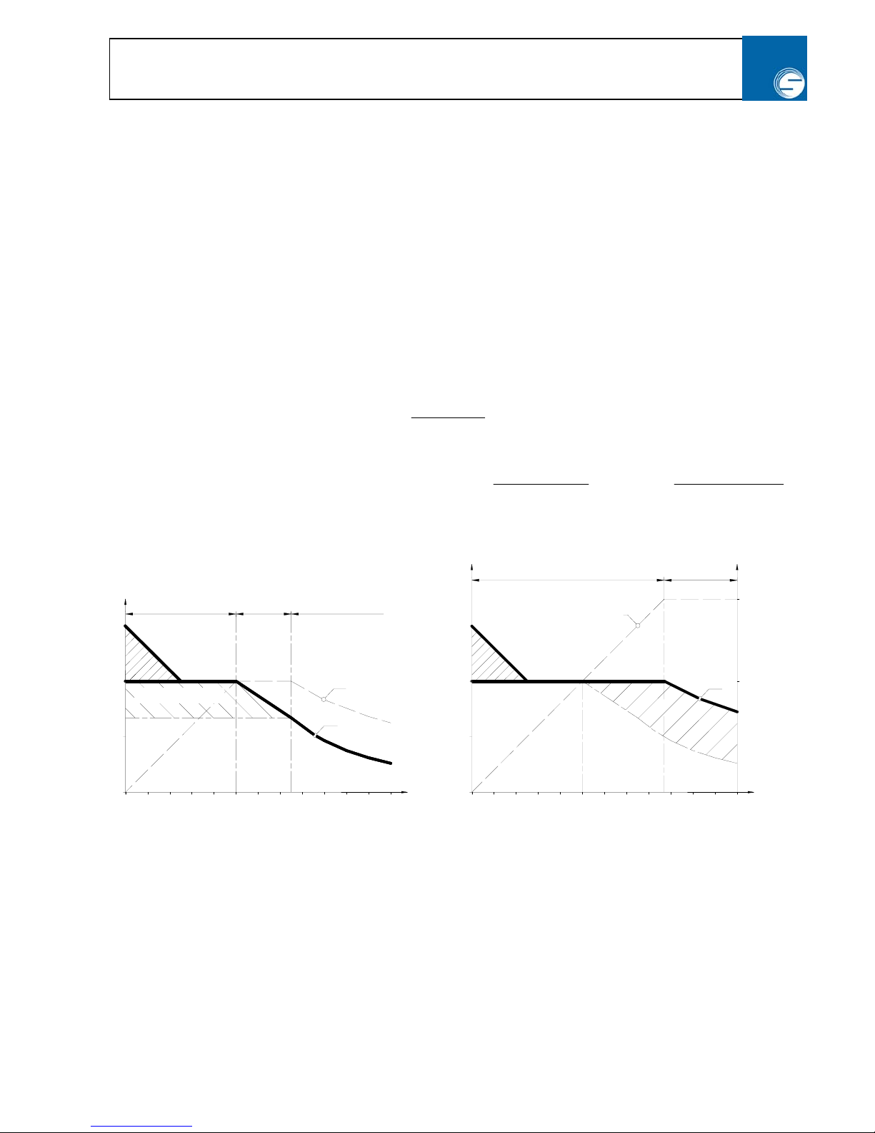
1.5 Power and torque curves
When setting up a drive the torque sequence must be considered in the wanted regulation area.
This can roughly be divided into 3 groups:
• Constantly torque in all regulation area e.g. conveyer
• Rising torque at speed acceleration e.g. Pumps or ventilation.
• Falling torque at speed acceleration e.g. drilling machines or tools machines.
Diagram below might help to choose the right function and power selection.
Power and torque curve
Zone 1: Power rises linear with frequency. Rotation torque M is constant (Mn).
Warning: By continuous run with motor torque below 20 Hz, use a motor size larger or a motor with
ventilation.
Zone 2:
Power is constant (Pn)
Torque falls with rising frequency
f
f
M
Knæk
∗
=
n
M
Zone 3:
Power and torque falls with rising frequency
f
f
P
Knæk
∗
∗
=
n
P5,1
2
2
n
M5,1
f
f
M
Knæk
∗∗
=
Fig. 1 Fig. 2
Frequency / Voltage point at 50 Hz Frequency / Voltage point at 87 Hz
If you choose to set the systems max frequency to
75 Hz instead of 50. Is it possible to equalize the
smaller motor torque with a larger gearing in the
gear.
Advantages:
• 1,5 times larger regulations area
• 1,5 times larger torque below 50Hz
• Higher start torque.
• Ventilation of motor might not be needed.
Suitable for 3 phased mains supply( SC3- ) and
motor voltages at 230 / 400V by setting the motor in
delta ∆. This way you take advantage of the linear
V/F curve until 87Hz. The motor is supplied with
230V at 50 Hz and 400V at 87Hz
Advantages:
• 1,73 times larger regulations area
• 1,73 times larger motor power at 1,73 times
larger frequency inverter power.
• 100% torque from above 87 Hz.
[Hz]
50
20
10
30
40
50
60
100
70
80
90 110 120
150
[%]
P/M
P
M
50
20
10
30
50
40
60 80
70
90
[Hz]
110100 120
P/M
100
150
[%]
P
M
230
400
[V]
100
Zone 1 Zone 2 Zone 3
Zone 1 Zone 2
Motorvoltage
Frekvens
knækpunkt
Moment overskud f < 75Hz
Kun under start
(Boost)
Kun under start
(Boost)
Frekvens knækpunkt 87 Hz
Moment forhøjelse i
forhold til Fig. 1
Moment forhøjelse i
forhold til Fig. 1

Standard user guide
V51-00-V19 eng
-7- Rights to changes reserved
2 Installation
2.1 Generally
The SPEED-COMMANDER frequency inverter makes it possible to regulate the speed of a 3-phased AC
motor in power ranges until 22Kw
This manual must follow the inverter to secure correct installation. Please check the following points:
• Is the supplied device in the ordered power range?
• Is the inverter damaged under transportation?
• Is internal parts or connections plugs damaged or loose?
2.2 Mounting and installation
Safety precautions:
• Connection and setup must be carried out by trained personal.
• Trained personal must be familiar with all the safety precautions in this manual.
• Avoid touching the high voltage parts while powered up and until 5 min after mains power is
removed.
• When working with electrical systems always have a second trained person present in case of
emergency. This person could stop the system and give first aid.
• The motor terminal might contain high voltage even when motor not running.
• The inverter might start unwanted after power up (depends on the parameter setting).
• Connection and setup must be carried out in order of the electricity regulations.
Mounting description:
• The inverter must be mounted vertically to ensure that the heat sink functions correct and air can flow
freely through.
• When mounting inside a box ensure that there are at least 80mm for SC-750/5 to SC3-2200/5 and
100mm for SC3-4000/5 to SC3-22000/5 of free space over and under the inverter.
• In some cases it might be necessary to make calculations on the heat caused by the heat loss in the
inverter to ensure long lifetime.
• Avoid strong vibrations.
• The surrounding conditions of the inverter have influence on the lifetime and functionality of the
device.
Following demands must be kept:
• Ambient temperature 0º C to +40º C
• Humidity less than 90% (non condensation)
• Protection against noise, metal particles, humidity, corrosion and explosive gasses.
• Max. Altitude 1000m above sea
Standard user guide
V51-00-V19 eng
-8- Rights to changes reserved
Note!
• High ambient temperature reduces the electronically lifetime considerably.
• If fan is mounted please check it frequently.
• The Speed Commanderen must not be exposed to vibrations, humidity, water, dust and aggressive
gasses.
• Max altitude: 1000 meter above sea.
Reductions factor: Ambient temp.: Output current:
At ambient temperature above
40°C is it necessary to reduce the
max output current after
following table:
≤40°C
≤45°C
≤50°C
≤55°C
100%
85%
67%
50%
The suppluer / manufacture cannot be held responsible for any damage cursed by wrong treatment,
unauthorized operation or badly maintenance of the device.
Important! In case of problems that cannot be identified, please contact supplier
Find your contact here: www.speed-tech.dk
2.3 Decision of motor direction
First try the direction of the motor with TIP in small movements. The inverters control inputs are
disconnected so it enters the OFF mode. Now activate the
STEP/STORE button in 2 sec and while
pressing the button press the ▲ button for forward or the ▼ for reverse.
Note that STEP/STORE must
be activated else dose the motor stop. If the motor goes in the wrong direction, change 2 of the motor
wires. (Remove mains power and wait for 5 min)
NOTE The drive direction against the reference switch
is
reverse
2.4 Decision of the counter direction (When using encoder)
Check the counter direction in small steps with TIP function a described above. The counter must count
up when TIP’ing forward and down when reversing. If it is opposite change the encoders A/B wires
terminal 11 and 12.
Warning! Avoid touching the electronically parts while powered up and until 5 min after mains
supply has been removed. The frequency inverter restarts automatically when powered on if
automatic restart is selected.
 Loading...