


For the professional user
Operating Instructions
Für den professionellen Anwender
Betriebsanleitung
Class:
VTD410EV-SEPC1
Klasse:
Model:
1
Ausführung:
Machine number:
Maschinen-Nr.:
Dated:
Stand:
Spezialmaschinen GmbH

The sign of quality
ou nd the Strobel trademark on every Strobel
Y
machine leaving our works. And with good reason.
This symbol is a guaranteen of the high quality of
our products. Quality which creates trust – trust
in our technology, our service and, not least of all,
in our good name.
Im Zeichen der Qualität
ie nden die Strobel-Schutzmarke auf jeder
S
Strobel-Maschine, die unser Werk verlässt.
Und das aus gutem Grund. Denn dieses Zeichen
garantiert Ihnen die hohe Qualität unserer
Produkte. Qualität, die Vertrauen schafft – in unsere
Technik, unseren Service und nicht zuletzt in unseren
guten Namen.

A decision with future
trobel clients know that they can expect a particularly
S
high standard of performance from our company and our
machines. Now you have settled for one of our products.
For us this is a source of encouragement and of obligation
to Justify your trust.
If you wish to prot from the performance and efciency of
your Strobel machine as long as possible, exact handling
and thorough care is necessary. For this reason we kindly
request that you read the operating instructions closely.
It provides all the information you need for trouble free
operation.
And if you do happen to need a spare part the enclosed
spare parts list gives a complete overview. It is clearly
classied according to components so that you can nd the
required part quickly and easily. In order to avoid errors we
request you to quote machine class, machine number and
part number completely on your spare part order.
We wish you lots of success in your work with your new
Strobel machine.
Spezialmaschinen GmbH


Operating Instructions
STROBEL Class 410EV-SEPC1
Contents
1 General notes on safety ............................................................................................ 3
2 General ..................................................................................................................... 5
2.1 Operating instructions ..................................................................................... 5
2.2 Class identification, serial number and orientation of the machine................. 5
2.3 Range of application ....................................................................................... 5
2.4 Technical data ................................................................................................ 6
3 Installation and putting into service ........................................................................... 7
3.1 Unpacking the machine .................................................................................. 7
3.2 Installation ...................................................................................................... 7
3.3 Sense of rotation ............................................................................................ 9
3.4 Motor drive via V-belts .................................................................................... 9
3.4.1 Tensioning the V-belt ......................................................................... 9
3.5 Positions of the machine ................................................................................ 9
3.6 Lubrication .................................................................................................... 13
4 Instructions for use .................................................................................................. 14
4.1 Needles and threads .................................................................................... 14
4.2 Inserting the needle (Fig. 8) .......................................................................... 14
4.3 Threading and thread courses ...................................................................... 16
4.3.1 Threading ......................................................................................... 16
4.3.2 Thread courses ................................................................................ 16
4.4 Thread tension.............................................................................................. 18
4.5 Setting the stitch length ................................................................................ 19
4.6 Setting the material guide ............................................................................. 20
4.7 Sewing drive ................................................................................................. 20
1 BA_VTD410EV-SEPC1_A1_140417_en

5 Operating the machine ............................................................................................ 21
5.1 Right hand treadle ........................................................................................ 21
5.2 Operating the gathering device (EV) ............................................................ 21
5.2.1 Knee lever ........................................................................................ 22
5.2.2 Gathering (left hand treadle) ............................................................ 22
5.2.3 Operating the shaft coupling for the front cup .................................. 23
5.2.4 Setting the differential feed (Fig. 14) ................................................ 23
5.3 Inserting and removing the fabric ................................................................. 24
5.3.1 Sewing ............................................................................................. 24
6 Machine maintenance ............................................................................................. 25
6.1 Checking the oil level .................................................................................... 25
6.2 Oil drain tube ................................................................................................ 26
7 Variable sewing tools .............................................................................................. 26
Subject to change without prior notice
2 BA_VTD410EV-SEPC1_A1_140417_en

1 General notes on safety
The non-compliance wi th the fol l owing notes on safety can lead to bodily
injuries or to damages of the machine.
1. The machine must only be operated by persons familiar with the relevant
operating instructions and who have been instructed accordingly.
2. Before commissioning also read the notes on safety and the operating
instructions of the sewing drive manufacturer.
3. The machine must only be operated according to its designation and not
without the appropriate guards; all explicit safety regulations must also be
observed.
4. For threading, for changing the reels, for exchanging sewing tools such as
needles, grippers, stitch plate, transport devices, if necessary cutter and
cutting block, for cleaning, when leaving the workplace and for
maintenance work, switch off main switch or pull mains plug. With a
mechanically operated coupling motor without activation lock, wait until the
motor has stopped.
5. General maintenance work must only be carried out by appropriately
instructed persons in accordance with the operating instructions.
6. Repair, modification and maintenance work must only be carried out by
qualified staff or by appropriately instructed persons.
7. During maintenance and repair work at pneumatic devices, the machine
must be disconnected from the pneumatic supply network. Exceptions are
only admissible during adjusting work and function test by appropriately
instructed qualified staff.
8. Work at the electrical equipment must only be carried out by qualified
staff.
9. Work at parts and devices under voltage is not allowed. Exceptions are
regulated by the regulation EN50110 (DIN VDE0105).
10. Modification or alteration at the machine must only be undertaken under
consideration of all explicit safety regulations.
11. Only spare parts released by us for use are to be used during repairs.
12. The commissioning of the upper part is prohibited until it has been
determined that the entire sewing unit complies with the regulations of the
EC guidelines.
3 BA_VTD410EV-SEPC1_A1_140417_en

13. Warning notes in the operating instructions of the machine, which point
out special points of danger, are marked at the appropriate positions with
the safety symbol.
Warning notes in the operating instructions of the machine which point out
special dangers of injury for operating or qualified staff, are marked at the
appropriate positions with the symbol
it is essential that you observe and follow these notes as well as the
generally valid safety regulations.
4 BA_VTD410EV-SEPC1_A1_140417_en

2 General
2.1 Operating instructions
Any person involved in the installation, operation, maintenance and repair of
the machine must have read and understood the operating instructions and
mainly the safety instructions before starting the machine.
2.2 Class identification, serial number and ori e nt a t ion of the
machine
The operating side of the machine is the starting point for the description
referring to sides. The class identification (type) as well as the machine and
model number (after the dash) are located below the left handwheel.
These data are also shown on the front page of the cover sheet of the
Operating Instructions.
2.3 Range of applicati on
High capacity insoling machine for attaching the insole to uppers made of
Kevlar, leather and textile materials up to a total thickness of 11 mm, with
differential feed for gathering low extra fullness at the ball part and with shaft
coupling for the front cup drive.
Equipped with pneumatically controlled gathering device in combination with
the adjustable differential feed for gathering extra fullness at the toe, and shaft
coupling for the front cup drive.
5 BA_VTD410EV-SEPC1_A1_140417_en

2.4 Technical data
Speed: max. mechanically admissible 1800 min-1
Recommended rated speed 1500 min-1
Min. Motor power 550 W
Machine/pulley diameter dw 80
V-belt profile 10 x 6 mm
Stitch length 3 – 8 mm
Kind of stitch single thread overseam
Needle system 134
Needle size 120 – 180
Recommended thread twisted polyester filament
Thread size 20/3, 30, 40
Stitch type 501
Kind of feed rear and front cup drive
Pneumatic connection 6- 6.5 bar
Air consumption – average value 0.5 l per working stroke
Required space 0.7 x 1.06 m
Noise:
Average noise level at a speed of
n = 1900 min-1: LpAm 76 dB (A)
Noise test according to DIN 45635-48-1 KL3
6 BA_VTD410EV-SEPC1_A1_140417_en
3 Installati on a nd put t ing into service
3.1 Unpacking the machine
The machines of the series 400 are only supplied complete.
The thread stand, oil and other machine tool accessories located with in the
package.
Make sure that all accessories have been unpacked before throwing away any
packing material.
3.2 Installation
ATTENTION!
Danger of bodily injuries or finger bruises through pulling in
of garments or hairs!
The machine may not be operated without belt guards for
head and motor.
The electrical connection must be carried out according to the marking of the
cable or the supplied wiring diagram.
Check if all screws on the stand are tight and retighten them, if necessary.
Before putting the machine into service make sure that the electrical connecting
data on the motor's name plate, your electric network and the frequency, and all
other connecting values, e.g. for the air, correspond to the data shown on the
machine and the operating instructions.
Since feed cup opening and some other operations are realized pneumatically,
a compressed air connection of 6 bar is required (see point “2.4 Technical
data”). Regulation of the pressure by means of compressed air conditioner
293.0975 at the stand.
ATTENTION!
Before putting the machine into service make sure
that the electrical connecting data on the motor’s
name plate, your electric network, and all other connecting
values, e. g. for the air, correspond to the data shown on
the machine and the operating instructions.
All rust preventing agents, such as Vaseline and similar agents, have to be
wiped off carefully, particularly from the most important sewing tools.
7 BA_VTD410EV-SEPC1_A1_140417_en

Fig. 1
8 BA_VTD410EV-SEPC1_A1_140417_en

3.3 Sense of rotation
The correct sense of rotation of the hand wheel is clockwise in line of vision on
the hand wheel.
3.4 Motor drive via V-belts
3.4.1 Tensioning the V-belt
Caution! Danger of injury!
When checking the belt tension, switch off the machine at
the mains. Do not operate the machine without the belt
guard. Otherwise there is a DANGER of crushing
fingers, of injuries to the body and of pulling in parts of
clothing.
The tensioning of the V-belt is carried out by swivelling the motor underneath
the table plate after releasing the retaining nut with SW 24.
The V-belt must not be tensioned too much, especially with the stop motor. You
should be able to depress it with light thumb pressure by about 2 cm.
Too little V-belt tensioning can impair the positioning of the machine and
therefore impair the function sequence.
3.5 Positions of the ma c hine
Caution! Danger of injury!
Danger of crushing fingers and needle through stitching as
well as pulling in of parts of clothing.
Keep fingers and hands away from moving parts when
setting the position generator and checking the positions
with switched-on machine.
General:
The machine requires a pulse generator that is mounted on the main shaft
(handwheel) of the machine and that detects the mechanical position of the
machine and sends it to the control.
The pulse generator has to be mounted on the machine as follows:
The pulse wheel (1) from the encoder must be positioned so that the
outgoing edge (disc transition from "light" to "dark" in the machine direction)
in the sensor (2) when the machine with the needle reaches the front
9 BA_VTD410EV-SEPC1_A1_140417_en
position (Fig. 2).
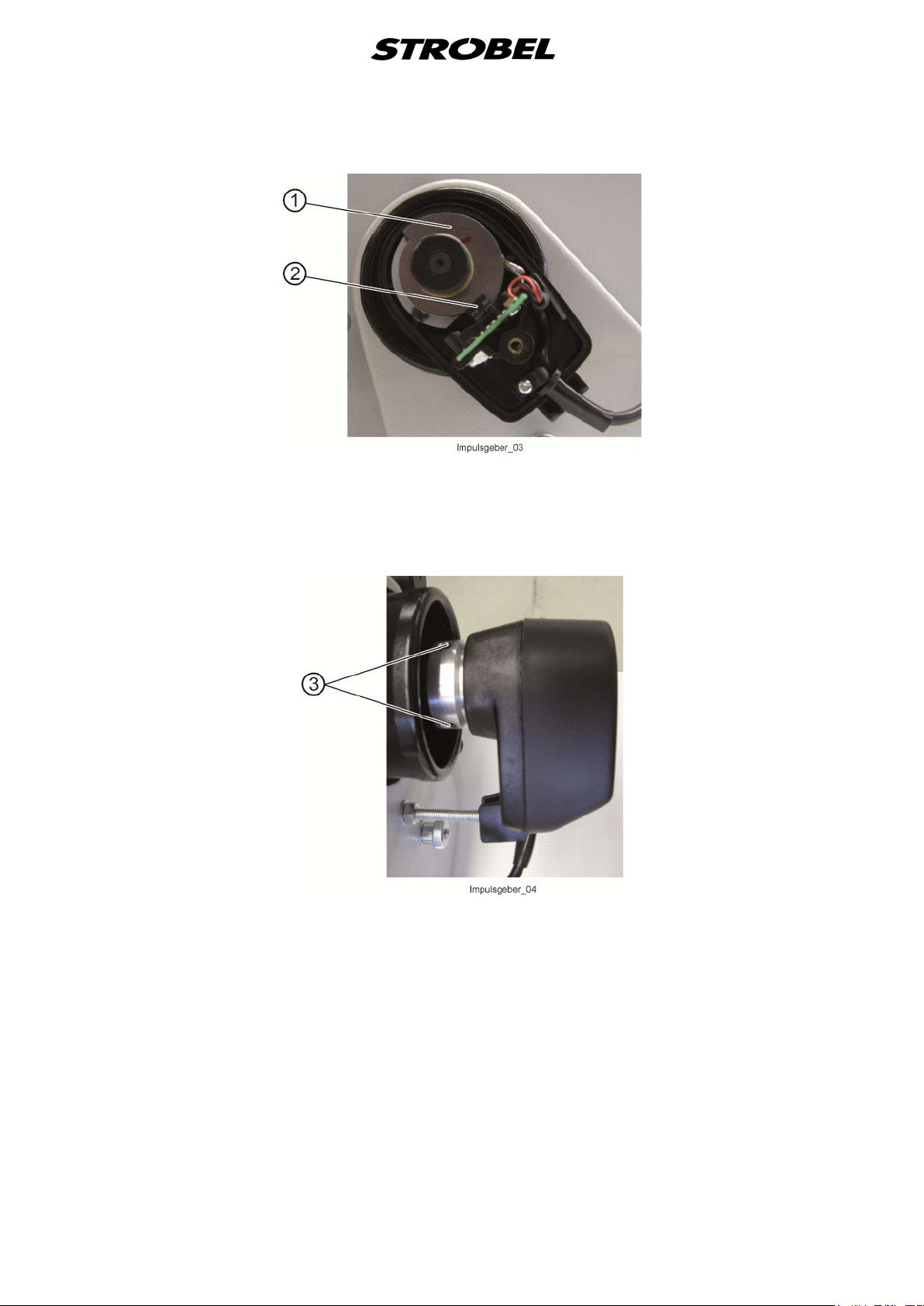
Fig. 2
To adjust or remove, loosen the two clamping screws (2), Fig. 3. Retighten
them well before restarting.
Fig. 3
The proper position of the position transmitter to the flange is marked with a
spot of paint.
10 BA_VTD410EV-SEPC1_A1_140417_en

Positions:
The machine requires two needle positions and, depending on sewing drive,
possibly also a reference position.
Reference position (if necessary, e.g. sewing drive DC1500-AB322A (Fig. 4)):
The reference position needs to be set so that the tip of the needle
concludes with the outer transport table edge in the direction of the
piercing.
Fig. 4
Needle position (when s top outs i de the stitch (Fig. 5)):
This needle position is important for inserting and removing the material
and is achieved by stepping back the right pedal (pedal position -2).
The needle position needs to be set so that the tip of the needle
concludes at a distance of 7 mm from the outer transport table edge in the
direction of the piercing. The tip is located thereby over the table.
The needle position is position 2 at the sewing drive.
Fig. 5
11 BA_VTD410EV-SEPC1_A1_140417_en

Needle position (when s top i n the stitch (Fig. 6)):
This needle position is important when stopping in the stitch (pedal
position 0), when swiveling in the separating plate of the hold-back device
and for the threading.
The needle position needs to be set so that the tip of the needle
concludes at a distance of 10 mm after the transport table edge in the
direction of the piercing. The tip is located thereby in front of the table.
The needle position is position 1 at the sewing drive.
Fig. 6
12 BA_VTD410EV-SEPC1_A1_140417_en

3.6 Lubrication
First lubrication (see also point “6.1 Checking the oil leve”).
Remove outer and inner machine cover and pour original STROBEL oil
supplied with the machine, from above.
To take off the inner cover first pull out the oil pipe 196.0716 which is plunging
in the oil rising pipe 193.0473 of the pump (Fig. 7).
Fig. 7
The special STROBEL oil (viscosity 46 c St) supplied with the machine should
always be used.
The oiling points are lubricated automatically, thus no maintenance is required
(see also point “6.1 Checking the oil leve/oil quantity”).
When remounting the inner cover make sure that the lower part of the main oil
pipe 196.0716 is pushed into the oil rising pipe 193.0473 of the oil pump
(Fig. 7). Otherwise the automatic lubrication does not work and the
machine will be heavily damaged through blocking of the shafts in the
bearings, etc.
Therefore the instructions should be foll owed carefully and, after filling
the machine with new oil, the machine shoul d be operated for a short
while and the corre ct working of the automatic lubri cation should be
controlled through the oil inspection glas s in the outer cover.
13 BA_VTD410EV-SEPC1_A1_140417_en

4 Instructions for use
for using different needle types.
4.1 Needles and threads
Use needle type 134.
Since there are several needle points available for the different materials to be
sewn, choose the most suitable needle point according to the needle
manufacturer's catalogue. Recommended needle type for leather is 134 LR, for
textile material 134 R.
When sewing fixed parts it may happen that the needle eye pastes up and
there is no correct loop formation.
Thicker and hard materials require thicker needles.
Guaranteed remark!
This machine has been set and sewn off with genuine
Strobel needles.
No guarantee can be granted if the settings are modified
4.2 Inserting the nee dle (Fig. 8)
ATTENTION!
Switch off the machine electrically and make sure that the
machine is really in the standstill position by stepping the
treadle for the motor control before changing the needle.
Otherwise DANGER of finger bruises and needle throughstitches.
Introduce the needle with its horizontal groove pointing downwards, push it to
the rear until it strikes against the needle stop 134.0251 (Fig. 8), then clamp it
by means of the screw 171.0406 (Fig. 9).
14 BA_VTD410EV-SEPC1_A1_140417_en

Fig. 8
Fig. 9
15 BA_VTD410EV-SEPC1_A1_140417_en

4.3 Threading and thread courses
ATTENTION! Danger of bodily injuries
Switch off machine electrically and confirm that the
machine is really in standstill position by operating the
treadle for the motor control before threading.
Otherwise danger of finger bruises and needle through
stitches.
CAUTION!
The function “Preparation threading” does
not
replace the electrical switching off of the machine during
threading.
This function serves only to ensure that the needle is
already in the correct position when the machine is
switched off.
4.3.1 Threading
Before the actual threading of the machine, the needle point can be brought
into the correct position with the function “Preparation threading”.
The function is activated or deactivated by the button “4” on the V810 operating
control and displayed with an arrow over the button or otherwise with the
“-Stop-” display in the display.
Please see the operating instruction manual for the sewing drive.
4.3.2 Thread courses
Because of the pneumatically controlled gathering device two successive
Asked thread tensions are grown. The front tension 838.0196 operating
normally, the rear thread tension 938.0196 activity occurs when the partition
plate of Gathering device swung and fullness, as is gathered at the toe. For this
shirring a firmer tension is needed to better fix the resulting material folds on
the shoe sole, and can get a good gathering. After swinging the partition plate,
the front is now more normal tension back into activity and that the rear thread
tension is released.
16 BA_VTD410EV-SEPC1_A1_140417_en

The thread course is as follows (Fig. 10):
Put the thread reel over the supporting bolt of the reel stand and pull the thread
end through the eye of bow 294.0052. Guide the thread through the rear eyes
of the thread guide 116.0355 (through 1 to 3 eyes depending on the thread)
and the thread tension discs 184.0049, through the front eye of thread guide
116.0355 to the thread tensions discs 184.0049 of the front thread tension
device, then through thread retaining spring 163.0008 (when sewing certain
materials there may be no need to guide the thread through retaining spring
163.0008) and to the front eye of the thread guide 116.0357 (Fig. 11).
Then guide the thread through the thread guide tube 184.0142 to the needle
bar head; from there below pin 160.0079 and above the thread clamping screw
138.0081. After guiding it through the needle clamp plate 285.0193 from the left
to the right, guide the thread through the needle eye from below
(Fig. 8 and Fig. 9).
Fig. 10
17 BA_VTD410EV-SEPC1_A1_140417_en

Fig. 11
4.4 Thread tension
The thread tension is regulated by means of the tension nut 279.0624 (Fig. 10)
depending on the thread type, quality and thickness. A thick and strong thread
requires a tight thread tension.
18 BA_VTD410EV-SEPC1_A1_140417_en

4.5 Setting the stitch length
ATTENTION!
Switch off the machine electrically and make sure that the
machine is really in standstill position by stepping the
treadle for the motor control before setting the stitch
length. Otherwise: DANGER of finger bruises and needle
through stitches/punctures.
As shown in Fig. 12, the stitch length can be regulated with the stitch regulating
knob 244.0209 in the left handwheel by turning it to the left or to the right up to
the limit stop. The stitch length can be regulated from approx. 3.0 to 8.0 mm.
Turning to the left results in a shorter stitch.
Turning to the right results in a longer stitch.
Fig. 12
19 BA_VTD410EV-SEPC1_A1_140417_en

4.6 Setting the material guide
ATTENTION!
Switch off machine electrically and make sure that the
machine is really in standstill position by stepping the
treadle for the motor control.
Otherwise: DANGER of finger bruises and danger of
injuries through the screw driver.
A difference is to be made between the rigid and the height-adjustable material
guides.
The rigid material guides are equipped with a fixed height limit stop and can
only be replaced by another material guide, if necessary (see fig. in the parts
lists - material guide).
The height-adjustable material guide can be adjusted by means of the knurled
nut. Make sure that the looper does not touch it.
4.7 Sewing drive
Machines of series 400 are equipped with modern DC-sewing drives as
standard equipment.
Please note that with these sewing drives quantity of stitches, sense of rotation,
switching time etc. can only be changed by programming.
The quantity of stitches cannot be influenced by changing the V-belt pulley.
Please take the steps to be made for the programming of the sewing drive from
the operation manual enclosed.
20 BA_VTD410EV-SEPC1_A1_140417_en

5 Operating the mac hine
The machine is operated with an electronic-pneumatic control. The operation is
very easy:
5.1 Right hand treadle
By means of the right hand treadle the motor is operated, the front cup is
opened and the needle is positioned.
The process is as follows:
- Usually the front cup is opened.
- Insert the material.
- Press the pedal forward slightly (pedal position +1/2), pressure plate is
closed.
- Press the pedal further to the front (pedal position ≥ +1), machine sews all
the faster the further the pedal is pressed forward.
- Return pedal to idle position (pedal position 0), machine stops in the
needle position 1 (the needle now stands about 10 mm in front of the
transport plate). (See also point “5.2 Operating the gathering device (EV)”
- “5.2.2 Gathering (left hand treadle)”)
- Press pedal all the way back (pedal position -2), machine moves to needle
position 2 and the pressure plate is opened (the needle stands with the tip
about 4 mm within the transport plate).
5.2 Operating the gathe ring device (EV)
If the pneumatic gathering device is needed to gather extra fullness, e.g. at the
toe part, stop the sewing process at the previously determined point - as
described in point “5.1 Right hand treadle” the needle is now in the material and
keeps it in this position (Fig. 13).
Fig. 13
Keep insole and upper apart in a way that the gathering device can swivel down
between the two parts.
21 BA_VTD410EV-SEPC1_A1_140417_en

5.2.1 Knee lever
By means of the knee lever the partial cup opening needed for the swivelling of
the gathering device is operated. The front cup opens up to the previously set
extent (setting see point “3.6.2.2 Mounting of pneumatically controlled shaft” in
mechanics instruction). The gathering device swivels down between insole and
upper, the front cup is closed. The whole process is done automatically, sewing
can be continued.
5.2.2 Gathering (lef t ha nd t readle)
After having placed the gathering device between insole and upper, the
differential feed can be operated by stepping on the left hand treadle. The more
the treadle is pressed down the more material is gathered. However, the
gathering effect can be limited to a certain value by means of the limit screw
138.0275 at the crank (Fig. 14).
As described in point “0 Threading”, additional thread tension device 938.0196
is actuated automatically during the gathering process. The higher thread
tension can be set depending on the material.
Also, if necessary, little extra fullness e.g. at the ball part can be gathered
during sewing by just operating the left hand treadle (without using the
gathering device or the knee lever respectively).
Fig. 14
After the gathering process (when reaching the next mark at the shoe) the
sewing process is stopped again briefly,
The knee lever is operated again, the front cup opens briefly, the gathering
device swivels up, the front cup is closed, and the sewing process can go on.
Then operate the right hand treadle as described in point “5.1 Right hand
treadle” and remove the sewn part.
This process can be repeated at any time.
22 BA_VTD410EV-SEPC1_A1_140417_en

5.2.3 Operating the shaf t c oupling for the front c up
To eliminate the blocking effect between material and feed cups, mainly when
sewing a small radius (heel parts) caused by the double feed system, the front
cup drive is equipped with a shaft coupling which can be operated electro
pneumatically by means of the left hand treadle.
When reaching the heel part the front cup drive can be interrupted by heeling
the left hand treadle, the sewing process can be terminated.
When reaching the straight shoe part, the left hand treadle is brought back to
its 0-position, the front cup drive is reactivated.
This process can be repeated at any position, unless the gathering device is
actuated.
5.2.4 Setting the differential feed (Fig. 14)
As described in point “5.2 Operating the gathering device (EV)”, for gathering
extra fullness the gathering device is swiveled down at a certain point of the
shoe. In “0” position of the stop bolt 138.0273 the feed cups run synchronously.
When setting it down to the lowest point on the selector gate (figure 6) the front
cup reduces its speed down to a total of 48 % of the rear cup speed.
Which position is suitable has to be determined by means of tests and the
different materials.
23 BA_VTD410EV-SEPC1_A1_140417_en

5.3 Inserting and re m ovi ng t he fabric
ATTENTION!
The operating personnel should observe the sewing range
carefully during the sewing.
Otherwise: DANGER of finger bruises and needle through
stitches/punctures.
When the machine is in standstill position and the needle is placed approx.
7 mm within the feed cup, by opening the front cup up to approx. 14 mm by
either actuating the treadle or the pneumatic cup opening the sewing material
can be inserted or removed easily.
Put the sewing material edge to edge and then place it up to the height limit
stop of the material guide, close the front cup and start sewing.
When using a stop motor the needle is positioned automatically after the
sewing process when heeling the treadle.
Not till then the thread can be torn over the edge of the feed cup and the
material can be removed, or the material is removed and the thread is cut using
scissors.
5.3.1 Sewing
Class VTD410EV is used for attaching the insole to the upper. A pneumatically
controlled gathering device in combination with a differential feed adjustable
during sewing (see point “5.2.4 Setting the differential feed (Fig. 14)”) facilitates
gathering of extra fullness at the toe part of Vulcano and leather shoes of a
medium thickness. The result is a neat seam which is completely covered
during the subsequent vulcanizing process .
24 BA_VTD410EV-SEPC1_A1_140417_en

6 Machine maintenance
ATTENTION!
Switch off the machine electrically and confirm that the
machine is really in standstill position by stepping the
treadle for the motor control.
Otherwise: DANGER of finger bruises and needle through
stitches/punctures.
The machine is maintenance free due to the automatic lubrication system (see
point “3.6 Lubrication”), only the oil drain hole “B” should be cleaned from dirt
and hair once a week, to enable the oil coming from the needle bar to drain off
(Fig. 12).
6.1 Checking the oil l e vel
Make sure that there is always sufficient oil in the machine to enable the pump
to submerge into the oil and to bring upwards the oil (see also point
“3.6 Lubrication”).
A plastic container with a capacity of exactly 1 litre is supplied with the machine.
After having filled the machine with one litre oil, the oil pump's suction piece is
submerged into the oil.
Oil quantity and cleanness should be checked every six to twelve months
maximum.
If the oil is still clean enough, the oil quantity can be checked using the plastic
container. Drain the oil into this container and refill it into the machine if the oil
quantity is still correct. It is recommended to order a second oil container to
complete the oil quantity to one liter, if necessary.
There is an oil inspection glass on the outer machine cover (Fig. 7) through
which the correct function of the automatic lubrication can be controlled.
The first oil change should be done after about six month’s operation.
25 BA_VTD410EV-SEPC1_A1_140417_en

6.2 Oil drain tube
For easier machine maintenance there is a oil draining tube 133.0742 going
through a table plate boring at the lower cover, i.e. waste oil can be drained
without the necessity to dismantle the machine head.
Oil drain tube 133.0742 is sealed by means of an oil retainer ring 190.0124 and
a screw 170.0900 (Fig. 15).
Fig. 15
To drain the waste oil put a container under the oil draining tube and remove
the screw 170.0900. Remount screw 170.0900 tightly after draining the oil.
Before putting the machine into service make sure that all protection devices
(cover, belt guard, etc.) are fully effective and that all screws are tight.
7 Variable sewing tools
The following chart shows all sewing tools available.
26 BA_VTD410EV-SEPC1_A1_140417_en

Class VTD410EV-SEPC1
Standard
182.0252
feed cup saw-teethed
Ø68,8 mm, pitch 2,25 mm
Optional Extra
for California shoes
182.0255
feed cup
Ø68,8 mm, pitch 1,5 mm
Optional Extra
for California shoes
182.0254
feed cup saw-teethed
Ø68,8 mm, pitch 2,25 mm
Standard
282.0256
front cup saw-teethed
Ø27,5 mm, pitch 2,25 mm
Optional Extra
for California shoes
282.0259
front cup
Ø27,7 mm, pitch 1,5 mm
Optional Extra
for California shoes
282.0258
front cup saw-teethed
Ø27,5 mm, pitch 2,2 mm
27 BA_VTD410EV-SEPC1_A1_140417_en


Und wir können noch mehr für Sie tun!
Unser Lieferprogramm bietet für jede Branche und
jegliche Anforderung genau die richtige Problemlösung.
And we can do a lot more for you!
Our range offers the correct problem solution for
every branch and for all requirements.
Für die Bekleidungsindustrie:
Ein- und ZweifadenHochleistungs-Saummaschinen
DoppelblindstichSaummaschinen
Zweifaden-Blindstich-
Stafermaschinen
Roll- und Flachpikiermaschinen
Pikier-Automat
und
weitere Spezial-Nähmaschinen
For the clothing
industry:
Single an two thread high
performance hemming
machines
Bluff edge hemming machines
Two thread blind stitch felling
machines
Roll and at padding machines
Automatic lapel padding
machine
and other special sewing
machines
Für die Schuhverarbeitung:
Einfaden-Überwendlichmaschinen mit und ohne
Differentialtransport
For the shoe industry:
Single-thread overseaming machines with and without differential feed
Für Kürschnereien
und Pelzkonfektion:
Pelzschnellnäher
Pelzpikiermaschine
Futterstafermaschine
For the fur industry:
Rapid fur sewing machines
Fur padding machine
Lining felling machine
Für Heimtextilien:
Ein- und ZweifadenBlindstichmaschinen
For the home textiles
industry:
Single and two thread
blind stitch machines
Für die Polsterverarbeitung:
Ein- und ZweifadenÜberwendlichmaschinen
Ein- und ZweifadenBlindstichmaschinen
For the upholstery
industry:
Single and two thread
overseaming machines
Single and two thread
blind stitch machines
Für die Konfektion
technischer Textilien:
Ein- und ZweifadenÜberwendlichmaschinen
For the processing
of technical textiles:
Single and two thread
overseaming machines

Noch Fragen?
Dann rufen Sie uns an, schreiben Sie uns oder
kommen Sie einfach bei uns vorbei.
Sie können jederzeit weitere Informationen über
unsere Produkte anfodern oder die StrobelNähmaschinen in unserem Ausstellungsraum live
erleben. Wir freuen uns auf Sie!
Any further questions?
Then phone, write or simply come and see us. You
can have further information about our products at
any time, or experience the Strobel machines live in
our show room. We’re looking forward to meeting you!
Sp ez i al ma s ch in e n Gm b H
Postfach 1242
82168 Puchheim
Siemensstraße 3
82178 Puchheim
DEUTSCHLAND
www.strobel.biz
Telefon: +49 89 80096-0
Telefax: +49 89 80096-190
 Loading...