


For the professional user
Mechanic‘s Instructions
Für den professionellen Anwender
Mechanikeranleitung
Class:
Klasse:
Dated:
Stand:
VEB200-1 Ausf. 2
VEB200-2 Ausf. 2
Spezialmaschinen GmbH

The sign of quality
ou nd the Strobel trademark on every Strobel
Y
machine leaving our works. And with good reason.
This symbol is a guarantee of the high quality of
our products. Quality which creates trust – trust
in our technology, our service and, not least of all,
in our good name.
Im Zeichen der Qualität
ie nden die Strobel-Schutzmarke auf jeder
S
Strobel-Maschine, die unser Werk verlässt.
Und das aus gutem Grund. Denn dieses Zeichen
garantiert Ihnen die hohe Qualität unserer
Produkte. Qualität, die Vertrauen schafft – in unsere
Technik, unseren Service und nicht zuletzt in unseren
guten Namen.

A decision with future
trobel clients know that they can expect a particularly
S
high standard of performance from our company and our
machines. Now you have settled for one of our products.
For us this is a source of encouragement and of obligation
to Justify your trust.
If you wish to prot from the performance and efciency of
your Strobel machine as long as possible, exact handling
and thorough care is necessary. For this reason we kindly
request that you read the operating instructions closely.
It provides all the information you need for trouble free
operation.
And if you do happen to need a spare part the enclosed
spare parts list gives a complete overview. It is clearly
classied according to components so that you can nd the
required part quickly and easily. In order to avoid errors we
request you to quote machine class, machine number and
part number completely on your spare part order.
We wish you lots of success in your work with your new
Strobel machine.
Spezialmaschinen GmbH


Mechanic’s instructions
STROBEL Classes VEB200-1 and VEB200-2
Contents
1 General notes on safety ............................................................................................ 5
2 General ..................................................................................................................... 7
2.1 Operating instructions ..................................................................................... 7
2.2 Class identification, serial number and orientation of the machine ................. 7
2.3 Range of applications ..................................................................................... 7
2.4 Technical data ................................................................................................ 8
2.5 Brief setting instruction for Cl. VEB200-1,-2 ................................................... 9
3 Hints for repair and settings .................................................................................... 10
3.1 Mounting the needle plate ............................................................................ 10
3.1.1 Removing the needle plate (Fig. 2) .................................................. 11
3.1.2 Remounting the needle plate (Fig. 2) ............................................... 11
3.1.3 Setting the needle plate (Fig. 1) ....................................................... 12
3.1.4 Replacing the needle glide plate (Fig. 3) .......................................... 12
3.1.5 Setting the cloth retainers (Fig. 4) .................................................... 13
3.2 Needle lever ................................................................................................. 14
3.2.1 Mounting (Fig. 5) .............................................................................. 14
3.2.2 Setting the needle stroke (Fig. 7) ..................................................... 15
3.3 Loop stroke (Fig. 6) ...................................................................................... 17
3.3.1 Setting the loop stroke (Fig. 7) ......................................................... 17
3.4 Looper .......................................................................................................... 18
3.4.1 Removing and remounting the looper (Fig. 7) .................................. 18
3.4.2 Removing and remounting the looper shaft (Fig. 7) ......................... 18
3.4.3 Looper deflection (Fig. 3) ................................................................. 18
3.4.4 Setting the looper (Fig. 8) ................................................................. 18
3.5 Feed dog (upper feed) (Fig. 10) ................................................................... 20
3.5.1 Setting the feed dog ......................................................................... 20
3.6 Feed plates ................................................................................................... 21
3.6.1 Setting the feed plates ..................................................................... 21
3.6.2 Setting the feed plate lifting (Fig. 10) ............................................... 21
3.7 Plunger ......................................................................................................... 22
3.7.1 Replacing the plunger shafts (Fig. 11) ............................................. 22
3.7.2 Setting the plunger (Fig. 12) ............................................................. 23
3.7.3 Setting the cloth support arm (Fig. 11) ............................................. 24
3.7.4 Setting the spring initial tension at the feathered plungers
(Fig. 11) ............................................................................................ 24
1 MA_VEB200-1-2_A2_181015_en

3.8 Thread trimmer (Fig. 14) ............................................................................... 25
3.8.1 Removing and remounting of the thread trimmer drive (Fig. 14) ...... 25
3.8.2 Adjustment (Fig. 14) ......................................................................... 27
3.8.3 Replacing the knife (Fig. 14) ............................................................ 28
3.9 Sense of rotation .......................................................................................... 28
3.10 Cutting position ............................................................................................. 28
3.11 Positions ....................................................................................................... 29
3.12 Setting the positions ..................................................................................... 32
3.12.1 General notes .................................................................................. 32
3.12.2 Setting the reference position .......................................................... 32
3.12.3 Setting positions 1 and 2 .................................................................. 33
3.13 Display of the needle positions ..................................................................... 34
3.14 Pneumatic lifting ........................................................................................... 35
3.14.1 Setting the lifting .............................................................................. 35
3.15 Sewing drive ................................................................................................. 35
3.16 Seam lock (Fig. 19) ...................................................................................... 36
3.16.1 Setting the feed dog at the seam lock .............................................. 36
Subject to change without prior notice
2 MA_VEB200-1-2_A2_181015_en

Appendix
Circuit diagrams
Electric mains, sewing drive - sewing machine lamp:
258.00.35 Mains connection plan cl. general
(AB611A with/without sewing machine lamp gen.)
Connecting the sewing ma chine:
258.21.63 Electrical connection plan cl. 45, 58, 103, 120, 170, VEB
258.21.75 Electrical connection plan cl. VEB with seam lock
259.00.37 Pneumatic circuit diagram cl. gen. with pneum. lifting
259.10.37 Pneumatic construction circuit diagram cl. gen.
with pneum. Lifting
259.00.65 Pneumatic circuit diagram
cl. VEB100-1, -2, -2W, VEB200-1, -2 with seam lock
259.10.65 Pneumatic construction circuit diagram
cl. VEB100-1, -2, -2W, VEB200-1, -2 with seam lock
Connecting Thread trimmer:
258.21.47 Electric connection diagram cl. Gen. – thread trimmer
Strobel - Switchable functions (DC1210-AB611A)
Strobel - Parameter list (DC1210-AB611A)
We reserve the right to make design changes.
3 MA_VEB200-1-2_A2_181015_en

4 MA_VEB200-1-2_A2_181015_en

1
General notes on safety
Every person in charge of setting up, operating, servicing and repairing the
machine must first read and understand the operating instructions and
particularly the safety instructions before starting up the machine.
Failure to comply with the following safety instructions can lead to bodily
injury or damage to the machine.
1. The machine must only be operated by persons familiar with the relevant
operating instructions and who have been instructed accordingly.
2. Before commissioning also read the notes on safety and the operating
instructions of the sewing drive manufacturer.
3. Only use the machine in the intended manner and never without the
provided guards. Always observe the pertinent safety regulations.
4. Switch off the main switch or pull the power plug for threading, changing
the reels, exchanging sewing tools such as needle, gripper, needle plate,
transport devices, possibly cutter and cutting block, for cleaning and when
leaving the workplace as well as for maintenance.
5. General maintenance tasks may be carried out only by properly trained
persons in accordance with the operating instructions.
6. Repair work, retrofitting and maintenance may be carried out only by
technicians or specially trained personnel.
7. When servicing or repairing pneumatic equipment, the machine must be
disconnected from the pneumatic supply. Exceptions are only allowed for
adjustment work and tests of functionality performed by specially trained
technicians.
8. Only specially qualified technicians may work on the electrical equipment.
9. It is forbidden to work on electrically live components! Exemptions are
covered by the EN50110 (DIN VDE0105) regulations.
10. Any retrofitting or alterations to the machine may only be performed under
strict compliance with all pertinent safety regulations.
11. Only use our approved spare parts when servicing and/or repairing the
machine.
12. It is forbidden to operate the sewing head until it is determined that the
entire sewing unit complies with EU provisions.
13. It is essential that you observe and follow these instructions as well as the
generally valid safety regulations.
5 MA_VEB200-1-2_A2_181015_en

14. Warning instructions given in the operating instructions that pertain to
especially dangerous parts of the machine must be indicated at these
positions using a safety symbol.
Warning instructions given in the operating instructions that pertain to
special injury hazards for operating personnel or technicians must be
indicated at these positions using a safety symbol.
6 MA_VEB200-1-2_A2_181015_en

2
2.1
2.2
2.3
General
Operating instructions
Any person involved in the installation, operation, maintenance and repair of
the machine must have read and understood the operating instructions and
mainly the safety instructions before starting the machine.
Class identification, serial num be r and orientati on of t he machine
The operating side of the machine is the basis for descriptions referring to
sides. The class identification (type) as well as serial and model number (after
the dash) is located on the right hand side of the housing. These data are also
shown on the front page of the operating instructions.
Range of applicati ons
Classes VEB200-1 and VEB200-2 are suitable for bluff edging thin fabrics up to
approx. 400 grammes.
The Kl.VEB200-1 has a fixed plunger on the left and a spring-loaded plunger
on the right as well as two spring-loaded cloth retainers on a 9.5 mm needle
plate.
The right cloth retainer is combined with a regulating screw which limits the
cloth retainer lift-off upwards.
The Kl.VEB200-2 has a spring-loaded plunger on the left and right. It is also
delivered with a 9.5 mm needle plate. Both cloth retainers are spring-loaded
here and combined with a knurled screw which limits the cloth retainer lift-off
upwards.
The range of applications of the different machines can be extended by
exchanging the variable sewing tools, i.e. those other fabric qualities than the
above mentioned ones can be sewn as well.
For variable sewing tools please see point 7 in operating instruction.
7 MA_VEB200-1-2_A2_181015_en

2.4
Technical data
Recommended rated speed 1800 min-1
Machine pulley diameter dw 71 mm
Min. sewing drive power 550 W
Toothed belt pulley/machine Z = 20
Toothed belt profile HTD 5M-15
Stitch length-upper feed 4 - 7 mm
(depend on fabric)
Kind of stitch single thread chain stitch bluff edge blind stitch
Stitch type 105
Needle system GROZ-BECKERT 1669 EEO
Needle size 80
Thread polyester continuous filament
Thread size 200/2
Pneumatic connection 6 bar
Average air consumption depending on the equipement
Required space 0.5 m x 1.1 m
Noise:
Average noise level at a speed of
n = 1800 min-1: LpAm 70 dB (A)
Noise test according to DIN 45635-48-1 KL3
8 MA_VEB200-1-2_A2_181015_en

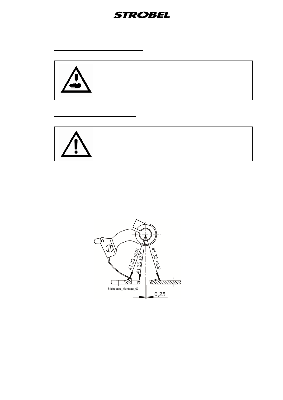
2.5
Brief setting instruction for Cl. VEB200-1,-2
theoretic needle radius 41.3 mm
left needle guide 41.33 +0.02 mm
needle glide plate 41.30 ±0.01 mm
right needle guide 41.36 +0.02 mm
needle stroke, needle eye to looper finger 1 +0.5 mm
ball pin to needle shaft 2 ±0.5 mm
Slot ball pin approx. 15°
Looper stroke 19 +0.5 mm
Pressures:
Feed plate left 12 N
Feed plate right 6 N
Cloth support arm meas. at plunger shaft 140 N
Ratchet pressure measured from below to pusher height:
VEB200-1 Ratchet right approx. 4 N
Ratchet left approx. 4 N
VEB200-2 Ratchet right, limited upwards approx. 4 N
Ratchet left, limited upwards approx. 4 N
Feed length approx. 4 - 7 mm
Lifting between needle plate
and feed plates approx. 11 mm
Lifting between needle
and plunger approx. 9 mm
Loop stroke 2.8 mm
Number of spot tacks 2 – 4 stitches
9 MA_VEB200-1-2_A2_181015_en
3
3.1
Hints for repai r and settings
ATTENTION, DANGER!
Observe safety and operating instructions before realizing
any maintenance and repair works.
Failure to do so may result in heavy bodily injuries.
Mounting the needle plate
ATTENTION!
Switch off machine electrically!
Needle plates are set at works and can be replaced easily as complete kit.
When replacing the needle guide the dimensions have to be checked by means
of a gauge as shown in Fig. 1. After removing the needle lever the gauge is
mounted to the needle shaft and senses the needle guides by turning the
handwheel.
Fig. 1
10 MA_VEB200-1-2_A2_181015_en

3.1.1
Removing the needle pla t e (Fig. 2)
1. Switch off machine electrically, cloth support arm is lifted.
2. Remove needle and needle lever.
3. Remove the thread trimmer’s drive unit as described under “3.8.1
Removing and remounting of the thread trimmer drive (Fig. 14)” or pull the
plug only.
4. Release needle plate fastening screws (1) and (2) and remove the
complete needle plate unit to the front.
Fig. 2
VEB200-1 VEB200-2
3.1.2
Remounting the needle plate (Fig. 2)
Install in reverse order. Make sure that both cloth retainers are positioned
centrally on the plungers and that the needle plate lies horizontally. Push the
needle plate bow completely upwards until threaded pin (3) fits closely to the
needle shaft bush.
11 MA_VEB200-1-2_A2_181015_en
3.1.3
3.1.4
Setting the needle plate (Fig. 1)
The theoretic needle radius of 41,3 mm should be 0,03 mm to 0,05 mm larger
at the left needle guide, 0,01 mm smaller to 0,01 mm larger at the needle glide
plate and 0,06 mm to 0,8 mm larger at the right needle guide.
The settings should be realized with a gauge. Deviations may deteriorate the
sewing result considerably and may cause damages or pre-mature waste of the
sewing tools.
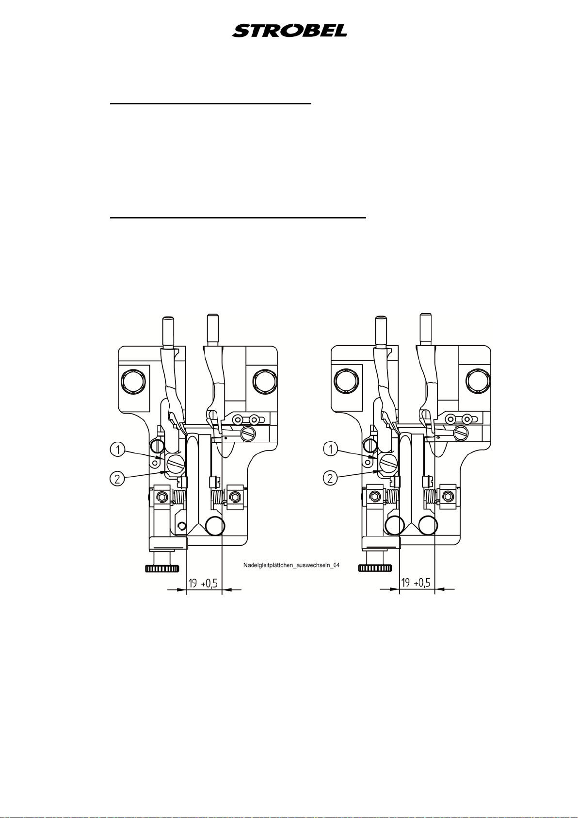
Replacing the needl e glide plate (Fi g. 3)
Loosen screw (2) to remove the needle glide plate (1). When re-mounting the
needle glide plate make sure that it fits closely to the needle plate bridge.
Fig. 3
VEB200-1 VEB200-2
12 MA_VEB200-1-2_A2_181015_en
3.1.5
Setting the cloth retainers (Fig. 4)
After replacing the needle plate (1) check if the cloth retainers (2) are placed
centrically on the plungers (3). If necessary, displace the cloth support arm
axially.
Fig. 4
On the Kl.VEB200-1 both cloth retainers are feathered.
The pressure of about 4N left and 4N right is set by the bushes (5) (Fig. 2).
On the Kl.VEB200-2 both cloth retainers are feathered and combined with a
setting screw (4) (Fig. 2) that limits the cloth retainer lift to the top.
Basic setting for the pressure of the two cloth retainers about 4N. When setting
the cloth retainer lift, the pressure changes.
This combination is called plunger stopper, but can be used only in combination
with feathered plungers.
Plunger stopper and feathered plunger prevent that outer seams of the sewing
material are punctured during the sewing across cross-seams and other
thickenings and undesired markings become visible.
13 MA_VEB200-1-2_A2_181015_en

3.2
3.2.1
Needle lever
Mounting (Fig. 5 )
ATTENTION!
Switch off machine electrically!
Release screw (1), swivel the thread take-up (2) and remove the needle lever
(3). When mounting the needle lever make sure that the needle is mounted
centrically to the needle channel and that the needle point is flush with the right
hand edge of the left hand needle guide.
Fig. 5
14 MA_VEB200-1-2_A2_181015_en

3.2.2
Setting the needle stroke (Fig. 7)
Set the needle stroke in a way that at a loop stroke of 2.8 +0.3 mm the left side
of the needle eye has a distance of approx. 1 mm to the right hand edge of the
large looper finger, the point of the large looper finger being above the needle
center (
To adjust the stroke turn the main shaft until screw (1) is in horizontal position
under the boring in the upper head side. Release the screw (Allan key size 4);
ball bolt (2) can be adjusted through the rear head side (remove the oval cover)
by means of a slotted screwdriver. Insert the ball bolt in horizontal position so
that the slot of the ∅6 bolt is placed vertically under the ∅7 bolt.
Clockwise turning means a larger needle stroke, anticlockwise turning results in
a smaller needle stroke. The distance ball bolt to needle shaft is
2 ±0.5 mm. Readjust the needle lever as per “3.2.1 Mounting” after adjusting
the needle stroke.
Tighten screw (1). Check looper and needle movements through turning the
main shaft by means of the handwheel.
Fig. 6).
Fig. 6
15 MA_VEB200-1-2_A2_181015_en

Fig. 7
16 MA_VEB200-1-2_A2_181015_en

3.3
3.3.1
Loop stroke (Fig. 6)
The loop stroke is the needle’s way from its right cusp point to the point where
the point of the large looper finger is placed above needle center.
Setting the loop stroke (Fig. 7)
ATTENTION!
Switch off machine electrically!
At factory the loop stroke is set to 2.8 mm (Fig. 6).
Adjustment:
- Screw out universal joint : smaller loop stroke
- Screw in universal joint : larger loop stroke
Thread pitch = 0.5 mm per turn.
Proceed as follows to turn the looper shaft:
1. Release screw (3) and push looper (10) to the front.
2. Release nut (4) on the looper shaft.
3. Release screws (5) in connecting rod head (6).
4. Loosen set collar (7) and pull out looper shaft and connecting rod head (6)
from universal joint (8).
Do not release bolt (9)!
The loop stroke is determined by means of a special gauge or calliper gauge.
17 MA_VEB200-1-2_A2_181015_en

3.4
3.4.1
3.4.2
3.4.3
Looper
Removing and remounting the looper (Fig. 7)
ATTENTION!
Switch off machine electrically!
Release cap screw (3) and pull the looper (10) towards the front.
When remounting the looper (10) make sure that it is completely pushed in and
that it’s positioning surface fits exactly to the looper take-up.
Tighten cap screw (3).
Removing and remounting the looper shaft (Fig. 7 )
The looper shaft with ball jointed lever (12) can be taken out after removing the
looper (10) and releasing set collars (7) and (11).
Looper deflection ( Fig. 3)
3.4.4
The looper deflection is 19 +0.5 mm (control dimension).
Setting the looper ( Fig. 8)
In the moment of the loop take-up the looper fingers should be placed 0.1 - 0.2
mm above the needle, also when a thicker needle is used. The needle should
not be touched!
The horizontal distance from the large looper finger to the needle eye should be
1.5 mm (
move centrically through the looper fingers. These values can be set through
turning and moving eccentric bolt (1) (release adjusting screw (2)) and through
turning the looper shaft against connecting rod head (6) (Fig. 7).
Proceed as follows to turn the looper shaft (Fig. 9):
- Release nut (4) on the looper shaft.
- Release screws (5) in connecting rod head (6).
- Slightly twist the looper shaft (1) with the open-end spanner.
Check the looper movement through carefully moving the main shaft by means
of the handwheel. Check if all fastening screws are tight!
Fig. 6). On the left side, when the loop is released, the needle should
18 MA_VEB200-1-2_A2_181015_en

Fig. 8
Fig. 9
19 MA_VEB200-1-2_A2_181015_en

3.5
3.5.1
Feed dog (upper feed) (Fi g. 10)
The machine is equipped with a pyramid-teethed feed dog (4). Its movement in
relation to the needle plate can be adjusted after releasing screws (5). Or it can
be replaced by saw-teethed feed dog.
Setting the feed dog
ATTENTION!
Switch off machine electrically!
1. Set maximum stitch length.
2. Clamp the feed dog so that it is parallel to the needle plate and that it
shows the teeth depth under the lower needle plate side. It should not
touch the needle plate opening but it should be placed to the needle as
close as possible.
It should be possible to place a paper of 0.2 mm thickness between the
transport supports and the needle plate precisely when the needle pierces, with
needle tip centrally between the plungers (check).
Observe the tipping point of the pressure foot!
20 MA_VEB200-1-2_A2_181015_en

3.6
3.6.1
3.6.2
Feed plates
Setting the feed plates
ATTENTION!
Switch off machine electrically!
The feed plates should tilt easily and should sit close to the needle plate. To
guarantee a material feed free of twist, the pressure should be set to 12N on
the left and to 6N on the right side, measured at the pivot of the feed plates.
Tense the tension springs correspondingly (Setting screws on the left back side
and on the right on the top side of the material support arm).
Setting the feed plate lifti ng ( Fig. 10)
When lifting the cloth support arm the feed plates are pressed downwards.
Adjustable eccentric bolt (1) in cloth support arm extension and threaded pin (2)
in lever (3) serve as limit stop. With the cloth support arm being in its utmost
upper position there should be a play of approx. 1 to 2 mm between lever and
bolt to guarantee a secure pressing of the feed plates to the needle plate at any
stitch depth regulation.
Fig. 10
21 MA_VEB200-1-2_A2_181015_en

3.7
3.7.1
Plunger
ATTENTION!
Switch off machine electrically!
Replacing the plunger shafts (Fig. 11)
1. Remove cloth support arm extension.
2. Remove the rubber cover on the cloth support arm.
3. Loosen the screw (7) and the attachment screw (1) at lever (2) and pull
out the left plunger shaft (3).
4. Loosen the screw (7) and the attachment screw (4) at lever (5) and pull
out the right plunger shaft (6).
Assembly viceversa. Set the plunger shafts free of any play!
Fig. 11
VEB200-1
VEB200-2
22 MA_VEB200-1-2_A2_181015_en

3.7.2
Setting the plunger (Fig. 12)
Blind stitch settings for thick fabrics as shown in
shown in Fig. 12b.
The plungers are placed centrically in the needle plate opening and 0.2 mm left
from the needle shaft center (Fig. 13). For needle penetration the left plunger
should already be in standstill position when the needle point is still approx. 2.5
mm away (Fig. 13). The right plunger comes one revolution later.
Fig. 12a and for thin fabrics as
Fig. 12
a b
Fig. 13
23 MA_VEB200-1-2_A2_181015_en

3.7.3
3.7.4
Setting the cloth s upport arm (Fig. 1 1 )
Set the cloth support arm upwards by means of the stitch depth regulation until
the needle is lifted by 0.2 mm by means of the left plunger in its upper cusp
point. Use threaded pin (8) to limit the maximum height of the plunger and
fixate with threaded pin (9).
In this position the scale at the regulating knob should show “0”. The cloth
support arm should be axially free of any play.
Setting the spri ng initial tension at the feathered plungers (Fig. 11)
The right plunger is kept under tension at both classes by a spring.
The left plunger is feathered only with the cl. VEB200-2. It is kept under tension
by a spring. By turning the cylinder head screw 170.0261 with a screwdriver
(from the machine accessories) the pressure can be increased or lowered.
24 MA_VEB200-1-2_A2_181015_en

3.8
3.8.1
Thread trimmer (Fig. 14)
The blade of the thread trimmer is activated by a rotary magnet, to which an
electric release control system (microswitch) is connected. This prevents the
machine from starting when the blade is no longer in its inital position. Thus the
release control system prevents a possible collision between blade and looper.
Removing and remounting of t he t hread trimmer drive (Fig. 14)
Attention!
Switch off machine electrically!
1. Remove plug (1).
2. Loosen the screw (2) and remove from blade (3), spring (4) and disc (5).
3. Loosen the screw (6) on the needle plate clamp (7) and remove the thread
trimmer drive.
4. Installation in reverse order.
Ensure the blade is in corre ct position on the shaft!
25 MA_VEB200-1-2_A2_181015_en

Fig. 14
26 MA_VEB200-1-2_A2_181015_en

3.8.2
Adjustment (Fig. 14)
- The thread trimmer drive must be inserted as far as it will go into the needle
plate clamp.
Swivel the drive backwards so that there is a gap of about 1 mm between
the drive and the sewing head.
- The blade of the knife has until about 2 - 3 mm from needle lever, stand
forward, readjust if necessary.
Remove clamp (8).
Loosen the screws (9) and (10) on the small gearwheel (11) and adjust by
turning the blade shaft.
Push together gearwheel and blade shaft to the limit and tighten.
- Setting the microswitch (12) and gearwheel (11).
- When replacing the rotary magnet (13), ensure that the tooth gap between
the gearwheels is approx. 0.1 mm.
Ensure free movement of parts!
Fig. 15
27 MA_VEB200-1-2_A2_181015_en

3.8.3
3.9
Replacing the knif e (Fig. 14)
Attention!
Switch off machine electrically!
To replace cylinder head screw (2), unscrew it (hold shaft (14) with open-end
wrench 5 mm).
Caution: Do not hold onto the rotary knob (15) since the gearwheels can be
damaged!
The nose of knife (3) should sit in the shaft's groove to guarantee the right
position for the thread trimming.
Turn the main shaft manually and check the trimming position. (Fig. 15)
Sense of rotation
The correct sense of rotation of the hand wheel is clockwise.
3.10
The positions are properly set in the factory.
Cutting position
The machine should be positioned in such a way as the pedal is stepped back
that the distance between looper and blade in cutting position is approx. 1 mm.
For Strobel and EFKA controls, this corresponds to parameter 171, position
P2E.
28 MA_VEB200-1-2_A2_181015_en

3.11
Positions
Function
Setting the reference position
This function sets the reference position.
Function
Setting positions 1 and 2
This function sets the two positions.
The AB611A control has two positions. The positions are set exclusively by
programming the control.
A position is determined by a position input and output value. The values
correspond to the number of increments (steps), counted from an entered
reference position. A rotation is divided into 360 steps (increments), i.e. 1 step
= 1 degree.
Parameter
F-170
Parameter
F-171
NOTE!
To ensure a safe and proper process, must be between the two positions
must defer by at least 50 steps (increments).
Additionally there must be 25 steps between position input value and
output value for the same position (very important for internal control
functions).
For the precise programming of the individual positions refer to chapter “3.12
Setting the positions”.
The setting of the positions can be easily checked using the F-172 function.
Refer to chapter “3.13 Display of the needle positions”.
29 MA_VEB200-1-2_A2_181015_en

Reference position:
Turn hand wheel in the direction of the machine until the tip of the needle lines
up with the right (inner) edge of the needle glide washers in the stitch-in
direction.
For that the right plunger needs to be up (Fig. 16).
Fig. 16
Information on programming of the positions on the motor can be found in the
accompanying sewing drive instructions.
Machine with or without thread trimmer:
Turn hand wheel in the direction of the machine until the hook of the thread
blade securely catches the thread loop above the looper without touching it.
(Fig. 17).
When using a motor with integrated position transmitter, appropriate ratio (2:1)
and toothed-belt drive, it needs to be observed that the left plunger is at top.
Please check by manual activation of the thread trimmer afterwards.
On machines without thread trimmer this position is approximately the left
reversal point of the needle.
Please note: This position is position 2 on motor!
Fig. 17
30 MA_VEB200-1-2_A2_181015_en

Notes for sewing drives which have two needle positions (i.e. sewing drive
DC1210-AB611A (Fig. 18)):
The above mentioned needle position is position 2 at the sewing drive.
Position 1 must be set at the sewing drive in such a way, that the point of the
needle (1) in the direction of stitch exit closes with the right (inner) edge of
the needle slide plate. At the same time, the thread loop lies tensioned
over the looper.
Fig. 18
31 MA_VEB200-1-2_A2_181015_en

3.12
3.12.1
3.12.2
Setting the positions
General notes
The individual positions of the machine (machine positions) can be found in the
operating manual of the sewing machine.
NOTE!
For sewing machines that actually need only one position, both positions
always need to be programmed anyway for the control programming. This
is because the needle does have to be positioned somewhere following a
change in display in observance of the notes in chapter “3.11 Positions”.
The setting of the positions can be easily checked using the F-172 function.
Refer to chapter “3.13 Display of the needle positions”.
Setting the reference position
After entering the code number “1907” and button “E” for the technician level:
- Select parameter F-170. Display shows: .1.7.0.
- Press “E” button. Sr1_
- Press “>>” button. P0 I_I
Turn the handwheel in the machine's direction of rotation
until the circulation symbol disappears from the display.
Set the handwheel or needle to the sewing machine's
reference position (Refer to chapter “3.10 Cutting
position”).
- Press “E” button. .1.7.1.
- Exit the programming level by pressing the “P” button
or
continue with chapter “3.12.3 Setting positions 1 and 2” as of step 2.
32 MA_VEB200-1-2_A2_181015_en

3.12.3
Setting positions 1 a nd 2
After entering the code number “1907” and button “E” for the technician level:
- Select parameter F-171. Display shows: .1.7.1.
- Press “E” button. Sr2_
- Press “>>” button. P1E
Turn the handwheel in the machine's direction of rotation
until “P1E” changes to the position value in the display.
Then set the handwheel or needle to the position 1 of the
sewing machine (Refer to chapter “3.10 Cutting position”).
Remember or record the position value.
- Press “E” button. P2E
Turn the handwheel in the machine's direction of rotation
until “P2E” changes to the position value in the display.
Then set the handwheel or needle to the position 2 of the
sewing machine (Refer to chapter “3.10 Cutting position”).
Remember or record the position value.
- Press “E” button. P1A
Turn the handwheel in the machine's direction of rotation
until “P1A” changes to the position value in the display.
Then turn the handwheel or needle until the position value
“P1E + 25” is displayed.
- Press “E” button. Display shows: P2A
Turn the handwheel in the machine's direction of rotation
until “P2A” changes to the position value in the display.
Then turn the handwheel or needle until the position value
“P2E + 25” is displayed.
- Press “P” button. .1.7.1.
- Press “P” button.
33 MA_VEB200-1-2_A2_181015_en

position 1
position 2
P1E
280
P2E
150
P1A
305
P2A
175
position 1
position 2
P1E
275
P2E
150
P1A
300
P2A
175
At least one cycle needs to be sewn so that the setting is saved before the
machine is switched off.
For class VEB200-1, -1F, -2, -2F:
For class VEB200-1RF, -2RF:
3.13
Depending on the looper and needle setting, the values could variate slightly.
Display of the needle positions
Function
Display of the Positions 1 and 2 (down / up)
The setting of the positions can be easily checked using this function.
After entering the code number “1907” and button “E” for the technician
level:
- Select parameter F-172. Display shows: .1.7.2.
- Press “E” button. Sr 3
- Turn handwheel according to the motor's direction of rotation.
Display on the control:
Parameter
F-172
Segment 5 is switched on ⇒ Position 1E
Segment 5 is switched off ⇒ Position 1A
Segment 6 is switched on ⇒ Position 2E
Segment 6 is switched off ⇒ Position 2A
- Press “P” button. .1.7.2.
- Press “P” button.
34 MA_VEB200-1-2_A2_181015_en

3.14
3.14.1
3.15
Pneumatic lifting
ATTENTION!
Switch off machine electrically!
Setting the lifting
Reduce the lifting speed of the cloth support arm at the one-way restrictor so
that there is no hard noise when the arm is lowered.
The piston in the pneumatic cylinder should move up to the limit stop. When the
cloth support arm is lowered it should be possible to press it down by approx. 1
mm.
Sewing drive
Separate operating instructions with programming instructions and wiring
diagrams are supplied with the sewing drive.
35 MA_VEB200-1-2_A2_181015_en

3.16
Seam lock (Fig. 19)
The seam lock is made at the seam end by lifting the feed dog.
Therefore the feed dog is lifted, the plunger is lowered and a second thread
tension is activated.
Fig. 19
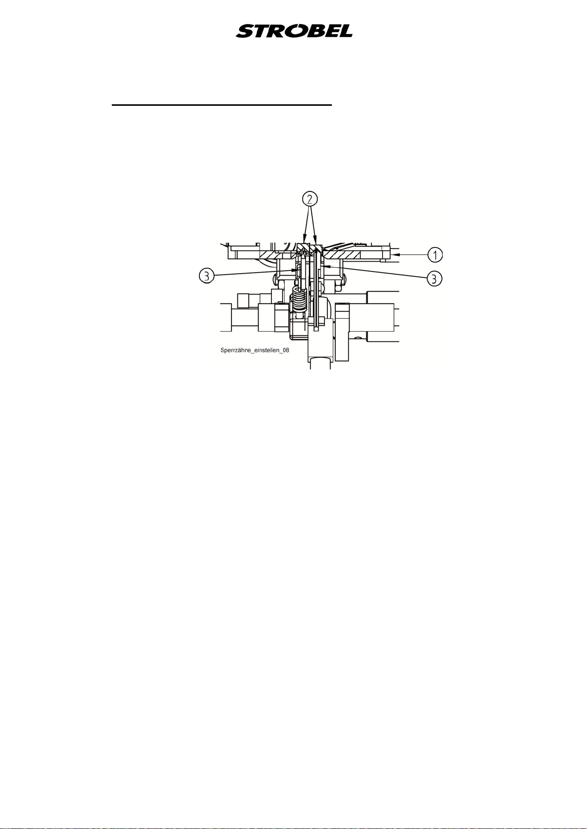
3.16.1
Setting the feed dog at the seam lock
The feed dog height is set by means of pneumatic cylinder (1) through lever (2)
and eccentric bush (3). The feed movement remains the same as before but
the feed dog does not catch the material.
The setting should be very smooth. Aluminium plate (4) is only fixed with one
screw and can be slightly displaced, therefore please make sure that none of
the moving parts touches the plate or jams.
Tense spring (5) at lever (2) by means of screw (6) in a way that during the
normal sewing operation the feed dog cannot be pressed upwards (through the
pressure of the feed plates). In this case the machine would rattle during
sewing.
36 MA_VEB200-1-2_A2_181015_en

ATTENTION: Set the feed dog in a way that during the end seam lock and
the programmable seam lock (lifted position) neither looper
nor looper shaft touch the feed dog in the upper part. In the
lower part the feed dog should move just above the material
but should not catch it.
With the feed dog not being lifted, i.e. during the normal sewing operation, it
should feed the material. This is a bit complicated since the feed dog can be
pushed in all directions due to the large borings.
The lifting height of the feed dog can be set through threaded pin (7) in the
aluminium plate (from below).
Threaded pin (7) is fixed through bolt (8) and threaded pin (9).
Please make sure that in lifted position the feed dog does not feed the material
and does not touch the looper.
Position of eccentric bushing:
outer steel bushing (10) : Eccentric backwards app. 10° up
inner bushing (3) : Eccentric forwards app. 25° down
37 MA_VEB200-1-2_A2_181015_en

Nähleuchte (allg.)
sewing light (gen.)
Netzanschluss
power connection
258.00.35
Netz-Anschlussplan Kl. allg.
(AB611A mit/ohne Nähleuchte allg.)
Mains connection plan cl. gen.
(AB611A with/without sewing light gen.)
Kabelbefestigung mit Kabelbinder
cable mounting with cable strap
3x 293.0290
Kabelzugentlastung
cable strain relief
193.0992
Rechtes Gehäuseteil
right casing
Linkes Gehäuseteil
left casing
Steuerkasten
control box
Efka-AB611A
Sicherung (8,0A M)
fuse (8,0A M)
293.0978
195.0042
gn-ge / gn-ye
bl / bu
br / bn
bl / bu
br / bn
bl / bu
br / bn
F 8,0A M
F 8,0A M

ST2
+5V / 0,2A
0V
+15V / 0,3A
+24V(1)
+24V(1)
+24V(1)
0V
POS1Q
POS2Q
G1Q
3A
+24V(1)
+24V(1)
3A
0,5A
0,5A
0,5A
6,5A
6,5A
3A
3A
0,5A
0,5A
0,5A
0,5A
LÜ ( MV1 )
FA
LSP
258.21.63en
Electrical connection plan cl. 45, 58, 103, 120, 170, VEB
(DC1200-AB611A)
Control box Efka drive
(1) Nominal voltage 24V, idle voltag e max. 30V
Designation
Strobel operating manual
Thread trimmer (FA) Output 1 (M1) 37
Run inhibition (LSP) Input 1 (IN1) 7
Lifting (LÜ) Press foot lifting (FL) 35
Designation
Efka operating manual
PIN
37 pin
Sub-D
16
4
17
Colour code
connection cable
yellow
brown
grey
blue
white
brown

ST2
+5V / 0,2A
0V
+15V / 0,3A
+24V(1)
+24V(1)
+24V(1)
0V
POS1Q
POS2Q
G1Q
3A
+24V(1)
+24V(1)
3A
0,5A
0,5A
0,5A
6,5A
6,5A
3A
3A
0,5A
0,5A
0,5A
0,5A
LÜ ( MV1 )
FA
LSP
VR ( MV2 )
258.21.75en
Electrical connection plan cl. VEB with seam lock
(DC12xx-AB611A)
Control box Efka drive
(1) Nominal voltage 24V, idle voltag e max. 30V
Designation
Strobel operating manual
Thread trimmer (FA) Output 1 (M1) 37
Run inhibition (LSP) Input 1 (IN1 7
Lifting (LÜ) Press foot lifting (FL) 35
Locking system (VR) Locking system (VR) 34
Designation
Efka operating manual
PIN
37 pin
Sub-D
16
4
17
17
Colour code
connection cable
yellow
brown
grey
blue
white
brown
green
brown

259.00.37
Pneumatischer Schaltplan Kl. allg. mit pneum. Lüftung
(Efka-DC1200/DC1210)
Pneumatic circuit diagram cl. gen. with pneum. lifting
(Efka DC1200/DC1210)
1A1
10bar max
0 Z 1
1V1
1V10
6bar
A
P
R
195.0513
0 Z 1 Wartungseinheit Service unit
1 V 1 3/2-Magnetventil "Lüftung" 3/2-solenoid-way valve "lifting"
1 V 10 Drosselrückschlagventil "Lüftung" throttle non-return valve "lifting"
1 A 1 Zylinder "Lüftung" cylinder "lifting"

259.10.37
Pneumatischer Bauschaltplan Kl. allg. mit pneum. Lüftung
(Efka-DC1200/DC1210)
Pneumatic construction circuit diagram cl. gen. with pneum. lifting
(Efka-DC1200/DC1210)
Wartungseinheit
service unit
293.0975
(293.0841)
297.0170
Lüftung
lifting
(293.0850)
Magnetventil
solenoid valve
293.0469
8
O
193.0478 3000 lg
6
O
193.0473 500 lg
R
1 V 1
P (R)
193.0658
193.0530
298.0179
293.0852
A
293.0850
193.0473 450 lg
O
6
298.0077
293.0470
293.0850
A
Kl. allg. 298.0546
B
Cl. gen.
Kl. 170 298.0680
293.0469
Cl. 170
195.0514
233.0713 2 Reduziernippel R1/4-R1/8 (nur Kl. 170) reduction nipple R1/4-R1/8 (only Cl. 170)
293.0469 2 Schalldämpfer R1/8 silencer R1/8
293.0470 1 Doppelnippel R1/8 nipple R1/8
193.0473 950 PA-Schlauch Ø6 PA hose Ø6
193.0478 3000 PA-Schlauch Ø8 PA hose Ø8
193.0530 1 Dichtungsring R1/8 gasket R1/8
193.0658 1 Muffe R1/8 bushing R1/8
293.0850 2 L-Einschraubanschluss R1/8-6 L-threaded connection R1/8-6
293.0852 1 G-Einschraubanschluss R1/8-6 threaded connection R1/8-6
293.0975 1 Wartungseinheit service unit
297.0170 1 Schnellverschlusskupplung Ø8 coupling Ø8
298.0077 1 Drosselrückschlagventil R1/8 throttle non-return valve R1/8
298.0179 1 3/2 Wege-Magnetventil 3/2-solenoid-way valve
298.0546 1 Kurzhubzylinder Ø32x25 (Kl. allg.) short stroke cylinder Ø32x25 (Cl. gen.)
298.0680 1 Kurzhubzylinder Ø50x25 (Kl. 170) short stroke cylinder Ø50x25 (Cl. 170)
2x 233.0713 (nur Kl. 170 / only Cl. 170)

259.00.65
Pneumatischer Schaltplan Kl. VEB100-1, -2, -2W, VEB200-1, -2
mit Nahtsicherung
Pneumatic circuit diagram cl. VEB100-1, -2, -2W, VEB200-1, -2 with seam lock
(Efka-DC12xx)
10bar max
1V10
0 Z 1
1V1
1A1
6bar
1A2 1A3 1A4
B
A
P
R
1V2
B
A
P
R
195.0515
0 Z 1 Wartungseinheit Service unit
1 V 1 4/2-Magnetventil "Lüftung" 4/2-solenoid-way valve "lifting"
1 V 2
1 V 10 Drosselrückschlagventil "Lüftung" One-way flow restrictor "lifting"
1 A 1 Zylinder "Lüftung" Cylinder "lifting"
1 A 2 Zylinder "Zwischenlüftung" Cylinder "intermediate lifting"
1 A 3 Zylinder "Transporteur" Cylinder "feed"
1 A 4 Zylinder "Fadenbremse" Cylinder "thread brake"
4/2-Magnetventil "Zwischenlüftung,
Transporteur,Fadenbremse"
4/2-solenoid-way valve "intermediate
lifting, feed, thread brake"

259.10.65
Pneumatischer Bauschaltplan Kl. VEB100-1, -2, -2W, VEB200-1, -2
mit Nahtsicherung
Pneumatic construction circuit diagram cl. VEB100-1, -2, -2W, VEB200-1, -2
with seam lock
(Efka-DC12xx)
Magnetventil
Wartungseinheit
2x 298.0510
solenoid valve
Beschriften
service unit
298.0512
L2
L1
L2
L1
293.0975
4x 293.0850
1V2
1V1
3x 293.0772
298.0511
(293.0850)
293.0469 2 Schalldämpfer R 1/8 silencer R 1/8
2x 293.0905
r
3
1V2
1V1
r
3
293.0469
2
2 B
293.0470 1 Doppelnippel R 1/8 nipple R 1/8
2x 293.0855
193.0473 2700 PA-Schlauch Ø6 PA hose Ø6
193.0478 3000 PA-Schlauch Ø8 PA hose Ø8
p
1
4
4
p
1
6
O
193.0473 720 lg
O
8
293.0772 3 Verschlußschraube R 1/8 lock screw R 1/8
293.0850 7 L-Einschraubanschluss R 1/8-6 L-threaded connection R 1/8-6
293.0853 2 L-Einschraubanschluss M5-4 L-threaded connection M5-4
293.0855 2 G-Steckanschluss 6-4 G-plug connection 6-4
293.0905 2 Y-Steckanschluss Ø6 Y-plug connection Ø6
293.0975 1 Wartungseinheit service unit
196.0716 2000 PA-Schlauch Ø4 PA hose Ø4
297.0170 1 Schnellverschlusskupplung Ø8 coupling Ø8
298.0077 1 Drosselrückschlagventil R 1/8 throttle non-return valve R 1/8
298.0211 1 Miniatur-Zylinder miniature cylinder
298.0510 2 4/2-Wege Magnetventil 4/2-solenoid-way valve
298.0511 1 Eingangsmodul G1/8 links input module G1/8 left
298.0512 1 Eingangsmodul G1/8 rechts input module G1/8 right
298.0547 1 Miniaturzylinder miniature cylinder
298.0582 1 Kurzhubzylinder short stroke cylinder
298.0583 1 Kurzhubzylinder short stroke cylinder
195.0516
O
4
196.0716 980 lg
O
6
193.0473 680 lg
O
4
196.0716 1000 lg
O
6
193.0473 660 lg
O
6
3x 293.0850
193.0473 570 lg
298.0077
A
293.0469
B
293.0853
298.0547
293.0853
298.0211
293.0470
feed dog
297.0170
lifting
Lüftung
193.0478 3000 lg
298.0852
298.0853
Transporteur
thread brake
Fadenbremse
(293.0841)

258.21.47
Elektrischer Anschlussplan Kl. allg.
Fadenabschneider
Electric connection diagram cl. gen.
Thread trimmer
Fadenabschneider
Thread trimmer
13,4
M16x 0,75
Schraubverschluß
screw coupling
Kontakt
Laufsperre
(NC)
Contact
run inhibition
(FA in Ruhestellung =
Kontakt geschlossen)
(FA at rest =
contact closed)
Rundstecker 4 pol.
Typ: Hirschmann Mas 3100 Ausf. B
circular plug 4-pin
type: Hirschmann Mas 3100 Ausf. B
Seitenansicht
side view
Verderansicht
front view
3
4
2
2
1
(C)
1
4
(NO)
rot/red
weiss/white
weiss/white
rt/rd
ws/wh
ws/wh
1 2 3 4
Drehmagnet
solenoid
Spannung/Voltage: + 24 VDC
Strom/electricity: 4 A
weiss/white
ws/wh
Spule
Spool
PIN Benennung/Description
1 NO Kontakt Laufsperre
Contact run inhibition
2 C Kontakt Laufsperre
Contact run inhibition
3 +24 V DC Spule Drehmagnet
DC Spool solenoid
4 0 V DC Spule Drehmagnet
DC Spool solenoid
195.0016

Explanation:
0 = Off
Button "E" Seg1
Button "E" Seg2
Button "+" Seg3
Button "+" Seg4
Button ">>" Seg5
Button ">>" Seg6
Button "-" Seg7
Button "-" Seg8
00
0
0
0
0
0
0
0
0
Strobel-Switchable Functions ( DC1210-AB611A )
"Control"
Machine class
F-290
Basic position "needle pos. 1"
Basic position "needle pos. 2"
Thread trimmer ON/OFF
Softstart ON/OFF
Not assigned
Mode
1 = On
Setting range
Preset at Mode 56 56 0 0 0 0 0 1 0 1
VEB200-1 56 0 0 0 0 0 1 0 1
VEB200-1F 56 0 0 1 0 0 1 0 1
VEB200-1RF 56 0 0 1 0 1 0 0 1
VEB200-2 56 0 0 0 0 0 1 0 1
56
1
1
Output M3 ON/OFF
1
1
1
1
Autom. lifting at the seam end
Autom. lifting in the seam
1
1
VEB200-2F 56 0 0 1 0 0 1 0 1
VEB200-2RF 56 0 0 1 0 1 0 0 1
Stand: 16.07.2018 - PT_AB611A-DC1210

00
Machine class
Strobel - Parameter list ( DC1210-AB611A )
F-467 F-290 F-365 F-001 F-002 F-003 F-010 F-013 F-014 F-019 F-026 F-100 F-110 F-111 F-112 F-113
Characteristic of the pedal EB401
Machine classes selection
Motor selection
Mode
Einstellbereich
Einheit min-1 min-1 min-1 min-1
Presetwert im Modus 56 3 56 0 3 003 001 0 0 0 3 4 002 200 2200 0600 0600
VEB200-1 9 56 1 0 001 001 0 0 0 1 4 002 100 0900 0300
1
10
56
0
2
beginning backtack "simple"
000
254
end backtack "simple"
Stitch number
000
254
end backtack "double"
Stitch number
000
254
OFF/ SIMPLE / DOUBLE
end backtackstiche
Stitch number
0
2
Thread trimmer
OFF / ON
0
1
OFF / ON
pedal position "-1"
Output 3
0
1
Lifting with
0
4
Stitch number softstart
0
4
000
254
Positioning speed n1
070
390
(setting range) n2-
n2_
9900
Maximum speed
Beginning backtack speed n4
0200
9900
End backtack speed n4
0200
9900
VEB200-1F 9 56 1 0 001 001 0 1 0 3 4 002 100 0900 0300
VEB200-1RF 9 56 1 0 001 001 1 1 0 3 4 002 100 0900 0300
VEB200-2 9 56 1 0 001 001 0 0 0 1 4 002 100 0900 0300
VEB200-2F 9 56 1 0 001 001 0 1 0 3 4 002 100 0900 0300
VEB200-2RF 9 56 1 0 001 001 1 1 0 3 4 002
Stand: 16.07.2018 - PT_AB611A-DC1210
100 0
900 0300

Stand: 16.07.2018 - PT_AB611A
Machine class
Strobe
Braking effect when changing the
Strobel - Parameter list ( DC1210-AB611A )
F-115 F-121 F-134 F-135 F-153 F-155 F-156 F-161 F-180 F-181 F-182 F-201 F-202 F-203 F-204 F-207
Einstellbereich
Einheit
Presetwert im Modus 56
Starting delay after the lifting signal
trimming device
0000
2550
Switch-off delay, control signal
of the motor
0
1
Number of turn-back steps
Direction of rotation
000
359
Switch delay for turn back
000
990
OFF / ON
0
1
lifting at pedal position "-1"
Switch delay of the
Turn back
0020
2550
switches off
000
500
of the lifting
000
600
Full drive time
Control signal trimming device
Lower limit of the n-max
Softstart speed n6
setting range
0070
1500
min-1 min-1 ms Grad ms ms ms ms %
0500 0200 0 1 05 1 0200 0 040 200 0 1000 300 500 040 15
0200
n2-
OFF / ON
Softstart
0
1
Festoon stitch backtack
OFF / ON
0
1
Holding force during
machine standstill
OFF / ON
00
50
0
4
Holding force (continuous duty) of
the lifting
F-254
1
values only with transmission ratio
1:1)
00
55
set-point <= 4 steps ((indicated
VEB200-1
VEB200-1F
VEB200-1RF
VEB200-2
VEB200-2F
VEB200-2RF
0250 0200 0 1 05 1 0200 1 040 200 0 1000 300 500 040 10
0250 0200 0 1 05 1 0200 1 040 200 0 1000 300 500 040 10
0250 0200 0 1 05 1 0200 1 040 200 0 1000 300 500 040 10
0250 0200 0 1 05 1 0200 1 040 200 0 1000 300 500 040 10
0250 0200 0 1 05 1 0200 1 040 200 0 1000 300 500 040 10
0250 0200 0 1 05 1 0200
1 0
40 200 0 1000 300 500 040 10

Stand: 16.07.2018 - PT_AB611A
Machine class
Braking effect when changing the
Stop time for switching the
Accelerating power of the drive
F-208 F-210 F-219 F-220 F-234 F-236 F-240
values only with transmission ratio
set-point <= 5 steps (indicated
(festoon stitch backtack)
backtack signal
1:1)
Positioning force when
stopping the drive
(indicated values only with
transmission ratio 1:1)
activated run inhibition
Restarting after
Lifting mode
In.1
Selecting the input function
F-241
-
F-246
Selecting the input function
In.2 - In.7
F-246 F-254 F-269 F-270 F-272 F-280 F-281 F-284
Selecting the input function
In.2 - In.7
Upper limit continuous duty
for lifting (F-204)
Positioning offset
position sensors
Selection of the
Transmission motor shaft to
machine shaft
thread trimmer
thread trimmer
Delay time
Output M3
On-time
Delay time
Einstellbereich
Einheit
Presetwert im Modus 56
VEB200-1
VEB200-1F
VEB200-1RF
VEB200-2
VEB200-2F
VEB200-2RF
00
55
20 140 04 20 1 2 00 00 124 100 015 0 1000 0100 0180 0000
20 140 04 12 1 2 00 00 100 015 0 1000 0100 0180 0000
20 140 04 12 1 2 06 00 100 015 0 1000 0100 0180 0000
20 140 04 12 1 2 06 00 100 015 0 1000 0100 0180 0000
20 140 04 12 1 2 00 00 100 015 0 1000 0100 0180 0000
20 140 04 12 1 2 06 00 100 015 0 1000 0100 0180 0000
20 1
000
5000055
ms % Ink ms ms ms
40 04 12 1 2 06 00 100 015 0 1000 0100 0180 0000
00
55
0
1
0
2
00
47
00
47
000
124
001
100
000
100
060150
9999
0000
5000
0000
5000
0000
5000


Und wir können noch mehr für Sie tun!
Unser Lieferprogramm bietet für jede Branche und
jegliche Anforderung genau die richtige Problemlösung.
And we can do a lot more for you!
Our range offers the correct problem solution for
every branch and for all requirements.
Für die Bekleidungsindustrie:
Ein- und ZweifadenHochleistungs-Saummaschinen
DoppelblindstichSaummaschinen
Zweifaden-BlindstichStafermaschinen
Roll- und Flachpikiermaschinen
Pikier-Automat
und
weitere Spezial-Nähmaschinen
For the clothing
industry:
Single and two thread high
performance hemming
machines
Bluff edge hemming machines
Two thread blind stitch felling
machines
Roll and at padding machines
Automatic lapel padding
machine
Für die Schuhverarbeitung:
Einfaden-Überwendlichmaschinen mit und ohne
Differentialtransport
For the shoe industry:
Single-thread overseaming machines with and without differential feed
Für Kürschnereien
und Pelzkonfektion:
Pelzschnellnäher
For the fur industry:
High-speed fur sewing machines
Für Heimtextilien:
Ein- und ZweifadenBlindstichmaschinen
For the home textiles
industry:
Single and two thread
blind stitch machines
Für die Polsterverarbeitung:
Ein- und ZweifadenÜberwendlichmaschinen
Ein- und ZweifadenBlindstichmaschinen
For the upholstery
industry:
Single and two thread
overseaming machines
Single and two thread
blind stitch machines
Für die Konfektion
technischer Textilien:
Ein- und ZweifadenÜberwendlichmaschinen
For the processing
of technical textiles:
Single and two thread
overseaming machines
and other special sewing
machines

Noch Fragen?
Dann rufen Sie uns an, schreiben Sie uns oder
kommen Sie einfach bei uns vorbei.
Sie können jederzeit weitere Informationen über
unsere Produkte anfodern oder die StrobelNähmaschinen in unserem Ausstellungsraum live
erleben. Wir freuen uns auf Sie!
Any further questions?
Then phone, write or simply come and see us. You
can have further information about our products at
any time, or experience the Strobel machines live in
our show room. We’re looking forward to meeting you!
Sp ezi al m as ch i ne n G mb H
Postfach 1242
82168 Puchheim
Siemensstraße 3
82178 Puchheim
DEUTSCHLAND
www.strobel.biz
Telefon: +49 89 80096-0
Telefax: +49 89 80096-190
 Loading...