

Strobel VEB200-1, VEB200-2 Mechanic's Instructions

For the professional user
Mechanic‘s Instructions
Für den professionellen Anwender
Mechanikeranleitung
Class:
Klasse:
Dated:
Stand:
VEB200-1 Ausf. 2
VEB200-2 Ausf. 2
Spezialmaschinen GmbH

The sign of quality
ou nd the Strobel trademark on every Strobel
Y
machine leaving our works. And with good reason.
This symbol is a guarantee of the high quality of
our products. Quality which creates trust – trust
in our technology, our service and, not least of all,
in our good name.
Im Zeichen der Qualität
ie nden die Strobel-Schutzmarke auf jeder
S
Strobel-Maschine, die unser Werk verlässt.
Und das aus gutem Grund. Denn dieses Zeichen
garantiert Ihnen die hohe Qualität unserer
Produkte. Qualität, die Vertrauen schafft – in unsere
Technik, unseren Service und nicht zuletzt in unseren
guten Namen.

A decision with future
trobel clients know that they can expect a particularly
S
high standard of performance from our company and our
machines. Now you have settled for one of our products.
For us this is a source of encouragement and of obligation
to Justify your trust.
If you wish to prot from the performance and efciency of
your Strobel machine as long as possible, exact handling
and thorough care is necessary. For this reason we kindly
request that you read the operating instructions closely.
It provides all the information you need for trouble free
operation.
And if you do happen to need a spare part the enclosed
spare parts list gives a complete overview. It is clearly
classied according to components so that you can nd the
required part quickly and easily. In order to avoid errors we
request you to quote machine class, machine number and
part number completely on your spare part order.
We wish you lots of success in your work with your new
Strobel machine.
Spezialmaschinen GmbH


Mechanic’s instructions
STROBEL Classes VEB200-1 and VEB200-2
Contents
1 General notes on safety ............................................................................................ 5
2 General ..................................................................................................................... 7
2.1 Operating instructions ..................................................................................... 7
2.2 Class identification, serial number and orientation of the machine ................. 7
2.3 Range of applications ..................................................................................... 7
2.4 Technical data ................................................................................................ 8
2.5 Brief setting instruction for Cl. VEB200-1,-2 ................................................... 9
3 Hints for repair and settings .................................................................................... 10
3.1 Mounting the needle plate ............................................................................ 10
3.1.1 Removing the needle plate (Fig. 2) .................................................. 11
3.1.2 Remounting the needle plate (Fig. 2) ............................................... 11
3.1.3 Setting the needle plate (Fig. 1) ....................................................... 12
3.1.4 Replacing the needle glide plate (Fig. 3) .......................................... 12
3.1.5 Setting the cloth retainers (Fig. 4) .................................................... 13
3.2 Needle lever ................................................................................................. 14
3.2.1 Mounting (Fig. 5) .............................................................................. 14
3.2.2 Setting the needle stroke (Fig. 7) ..................................................... 15
3.3 Loop stroke (Fig. 6) ...................................................................................... 17
3.3.1 Setting the loop stroke (Fig. 7) ......................................................... 17
3.4 Looper .......................................................................................................... 18
3.4.1 Removing and remounting the looper (Fig. 7) .................................. 18
3.4.2 Removing and remounting the looper shaft (Fig. 7) ......................... 18
3.4.3 Looper deflection (Fig. 3) ................................................................. 18
3.4.4 Setting the looper (Fig. 8) ................................................................. 18
3.5 Feed dog (upper feed) (Fig. 10) ................................................................... 20
3.5.1 Setting the feed dog ......................................................................... 20
3.6 Feed plates ................................................................................................... 21
3.6.1 Setting the feed plates ..................................................................... 21
3.6.2 Setting the feed plate lifting (Fig. 10) ............................................... 21
3.7 Plunger ......................................................................................................... 22
3.7.1 Replacing the plunger shafts (Fig. 11) ............................................. 22
3.7.2 Setting the plunger (Fig. 12) ............................................................. 23
3.7.3 Setting the cloth support arm (Fig. 11) ............................................. 24
3.7.4 Setting the spring initial tension at the feathered plungers
(Fig. 11) ............................................................................................ 24
1 MA_VEB200-1-2_A2_181015_en

3.8 Thread trimmer (Fig. 14) ............................................................................... 25
3.8.1 Removing and remounting of the thread trimmer drive (Fig. 14) ...... 25
3.8.2 Adjustment (Fig. 14) ......................................................................... 27
3.8.3 Replacing the knife (Fig. 14) ............................................................ 28
3.9 Sense of rotation .......................................................................................... 28
3.10 Cutting position ............................................................................................. 28
3.11 Positions ....................................................................................................... 29
3.12 Setting the positions ..................................................................................... 32
3.12.1 General notes .................................................................................. 32
3.12.2 Setting the reference position .......................................................... 32
3.12.3 Setting positions 1 and 2 .................................................................. 33
3.13 Display of the needle positions ..................................................................... 34
3.14 Pneumatic lifting ........................................................................................... 35
3.14.1 Setting the lifting .............................................................................. 35
3.15 Sewing drive ................................................................................................. 35
3.16 Seam lock (Fig. 19) ...................................................................................... 36
3.16.1 Setting the feed dog at the seam lock .............................................. 36
Subject to change without prior notice
2 MA_VEB200-1-2_A2_181015_en

Appendix
Circuit diagrams
Electric mains, sewing drive - sewing machine lamp:
258.00.35 Mains connection plan cl. general
(AB611A with/without sewing machine lamp gen.)
Connecting the sewing ma chine:
258.21.63 Electrical connection plan cl. 45, 58, 103, 120, 170, VEB
258.21.75 Electrical connection plan cl. VEB with seam lock
259.00.37 Pneumatic circuit diagram cl. gen. with pneum. lifting
259.10.37 Pneumatic construction circuit diagram cl. gen.
with pneum. Lifting
259.00.65 Pneumatic circuit diagram
cl. VEB100-1, -2, -2W, VEB200-1, -2 with seam lock
259.10.65 Pneumatic construction circuit diagram
cl. VEB100-1, -2, -2W, VEB200-1, -2 with seam lock
Connecting Thread trimmer:
258.21.47 Electric connection diagram cl. Gen. – thread trimmer
Strobel - Switchable functions (DC1210-AB611A)
Strobel - Parameter list (DC1210-AB611A)
We reserve the right to make design changes.
3 MA_VEB200-1-2_A2_181015_en

4 MA_VEB200-1-2_A2_181015_en

1
General notes on safety
Every person in charge of setting up, operating, servicing and repairing the
machine must first read and understand the operating instructions and
particularly the safety instructions before starting up the machine.
Failure to comply with the following safety instructions can lead to bodily
injury or damage to the machine.
1. The machine must only be operated by persons familiar with the relevant
operating instructions and who have been instructed accordingly.
2. Before commissioning also read the notes on safety and the operating
instructions of the sewing drive manufacturer.
3. Only use the machine in the intended manner and never without the
provided guards. Always observe the pertinent safety regulations.
4. Switch off the main switch or pull the power plug for threading, changing
the reels, exchanging sewing tools such as needle, gripper, needle plate,
transport devices, possibly cutter and cutting block, for cleaning and when
leaving the workplace as well as for maintenance.
5. General maintenance tasks may be carried out only by properly trained
persons in accordance with the operating instructions.
6. Repair work, retrofitting and maintenance may be carried out only by
technicians or specially trained personnel.
7. When servicing or repairing pneumatic equipment, the machine must be
disconnected from the pneumatic supply. Exceptions are only allowed for
adjustment work and tests of functionality performed by specially trained
technicians.
8. Only specially qualified technicians may work on the electrical equipment.
9. It is forbidden to work on electrically live components! Exemptions are
covered by the EN50110 (DIN VDE0105) regulations.
10. Any retrofitting or alterations to the machine may only be performed under
strict compliance with all pertinent safety regulations.
11. Only use our approved spare parts when servicing and/or repairing the
machine.
12. It is forbidden to operate the sewing head until it is determined that the
entire sewing unit complies with EU provisions.
13. It is essential that you observe and follow these instructions as well as the
generally valid safety regulations.
5 MA_VEB200-1-2_A2_181015_en

14. Warning instructions given in the operating instructions that pertain to
especially dangerous parts of the machine must be indicated at these
positions using a safety symbol.
Warning instructions given in the operating instructions that pertain to
special injury hazards for operating personnel or technicians must be
indicated at these positions using a safety symbol.
6 MA_VEB200-1-2_A2_181015_en

2
2.1
2.2
2.3
General
Operating instructions
Any person involved in the installation, operation, maintenance and repair of
the machine must have read and understood the operating instructions and
mainly the safety instructions before starting the machine.
Class identification, serial num be r and orientati on of t he machine
The operating side of the machine is the basis for descriptions referring to
sides. The class identification (type) as well as serial and model number (after
the dash) is located on the right hand side of the housing. These data are also
shown on the front page of the operating instructions.
Range of applicati ons
Classes VEB200-1 and VEB200-2 are suitable for bluff edging thin fabrics up to
approx. 400 grammes.
The Kl.VEB200-1 has a fixed plunger on the left and a spring-loaded plunger
on the right as well as two spring-loaded cloth retainers on a 9.5 mm needle
plate.
The right cloth retainer is combined with a regulating screw which limits the
cloth retainer lift-off upwards.
The Kl.VEB200-2 has a spring-loaded plunger on the left and right. It is also
delivered with a 9.5 mm needle plate. Both cloth retainers are spring-loaded
here and combined with a knurled screw which limits the cloth retainer lift-off
upwards.
The range of applications of the different machines can be extended by
exchanging the variable sewing tools, i.e. those other fabric qualities than the
above mentioned ones can be sewn as well.
For variable sewing tools please see point 7 in operating instruction.
7 MA_VEB200-1-2_A2_181015_en

2.4
Technical data
Recommended rated speed 1800 min-1
Machine pulley diameter dw 71 mm
Min. sewing drive power 550 W
Toothed belt pulley/machine Z = 20
Toothed belt profile HTD 5M-15
Stitch length-upper feed 4 - 7 mm
(depend on fabric)
Kind of stitch single thread chain stitch bluff edge blind stitch
Stitch type 105
Needle system GROZ-BECKERT 1669 EEO
Needle size 80
Thread polyester continuous filament
Thread size 200/2
Pneumatic connection 6 bar
Average air consumption depending on the equipement
Required space 0.5 m x 1.1 m
Noise:
Average noise level at a speed of
n = 1800 min-1: LpAm 70 dB (A)
Noise test according to DIN 45635-48-1 KL3
8 MA_VEB200-1-2_A2_181015_en

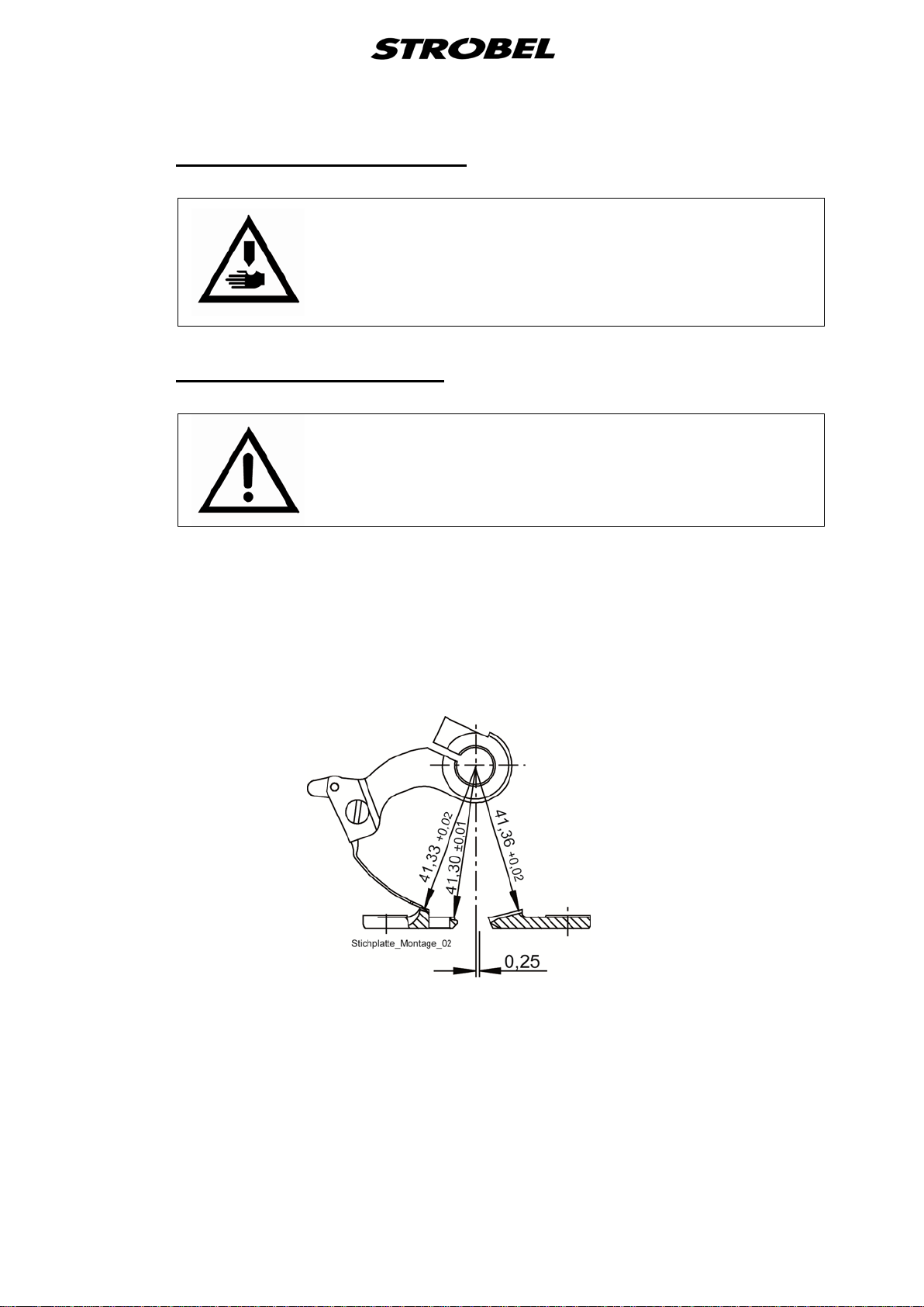
2.5
Brief setting instruction for Cl. VEB200-1,-2
theoretic needle radius 41.3 mm
left needle guide 41.33 +0.02 mm
needle glide plate 41.30 ±0.01 mm
right needle guide 41.36 +0.02 mm
needle stroke, needle eye to looper finger 1 +0.5 mm
ball pin to needle shaft 2 ±0.5 mm
Slot ball pin approx. 15°
Looper stroke 19 +0.5 mm
Pressures:
Feed plate left 12 N
Feed plate right 6 N
Cloth support arm meas. at plunger shaft 140 N
Ratchet pressure measured from below to pusher height:
VEB200-1 Ratchet right approx. 4 N
Ratchet left approx. 4 N
VEB200-2 Ratchet right, limited upwards approx. 4 N
Ratchet left, limited upwards approx. 4 N
Feed length approx. 4 - 7 mm
Lifting between needle plate
and feed plates approx. 11 mm
Lifting between needle
and plunger approx. 9 mm
Loop stroke 2.8 mm
Number of spot tacks 2 – 4 stitches
9 MA_VEB200-1-2_A2_181015_en
3
3.1
Hints for repai r and settings
ATTENTION, DANGER!
Observe safety and operating instructions before realizing
any maintenance and repair works.
Failure to do so may result in heavy bodily injuries.
Mounting the needle plate
ATTENTION!
Switch off machine electrically!
Needle plates are set at works and can be replaced easily as complete kit.
When replacing the needle guide the dimensions have to be checked by means
of a gauge as shown in Fig. 1. After removing the needle lever the gauge is
mounted to the needle shaft and senses the needle guides by turning the
handwheel.
Fig. 1
10 MA_VEB200-1-2_A2_181015_en

3.1.1
Removing the needle pla t e (Fig. 2)
1. Switch off machine electrically, cloth support arm is lifted.
2. Remove needle and needle lever.
3. Remove the thread trimmer’s drive unit as described under “3.8.1
Removing and remounting of the thread trimmer drive (Fig. 14)” or pull the
plug only.
4. Release needle plate fastening screws (1) and (2) and remove the
complete needle plate unit to the front.
Fig. 2
VEB200-1 VEB200-2
3.1.2
Remounting the needle plate (Fig. 2)
Install in reverse order. Make sure that both cloth retainers are positioned
centrally on the plungers and that the needle plate lies horizontally. Push the
needle plate bow completely upwards until threaded pin (3) fits closely to the
needle shaft bush.
11 MA_VEB200-1-2_A2_181015_en
3.1.3
3.1.4
Setting the needle plate (Fig. 1)
The theoretic needle radius of 41,3 mm should be 0,03 mm to 0,05 mm larger
at the left needle guide, 0,01 mm smaller to 0,01 mm larger at the needle glide
plate and 0,06 mm to 0,8 mm larger at the right needle guide.
The settings should be realized with a gauge. Deviations may deteriorate the
sewing result considerably and may cause damages or pre-mature waste of the
sewing tools.
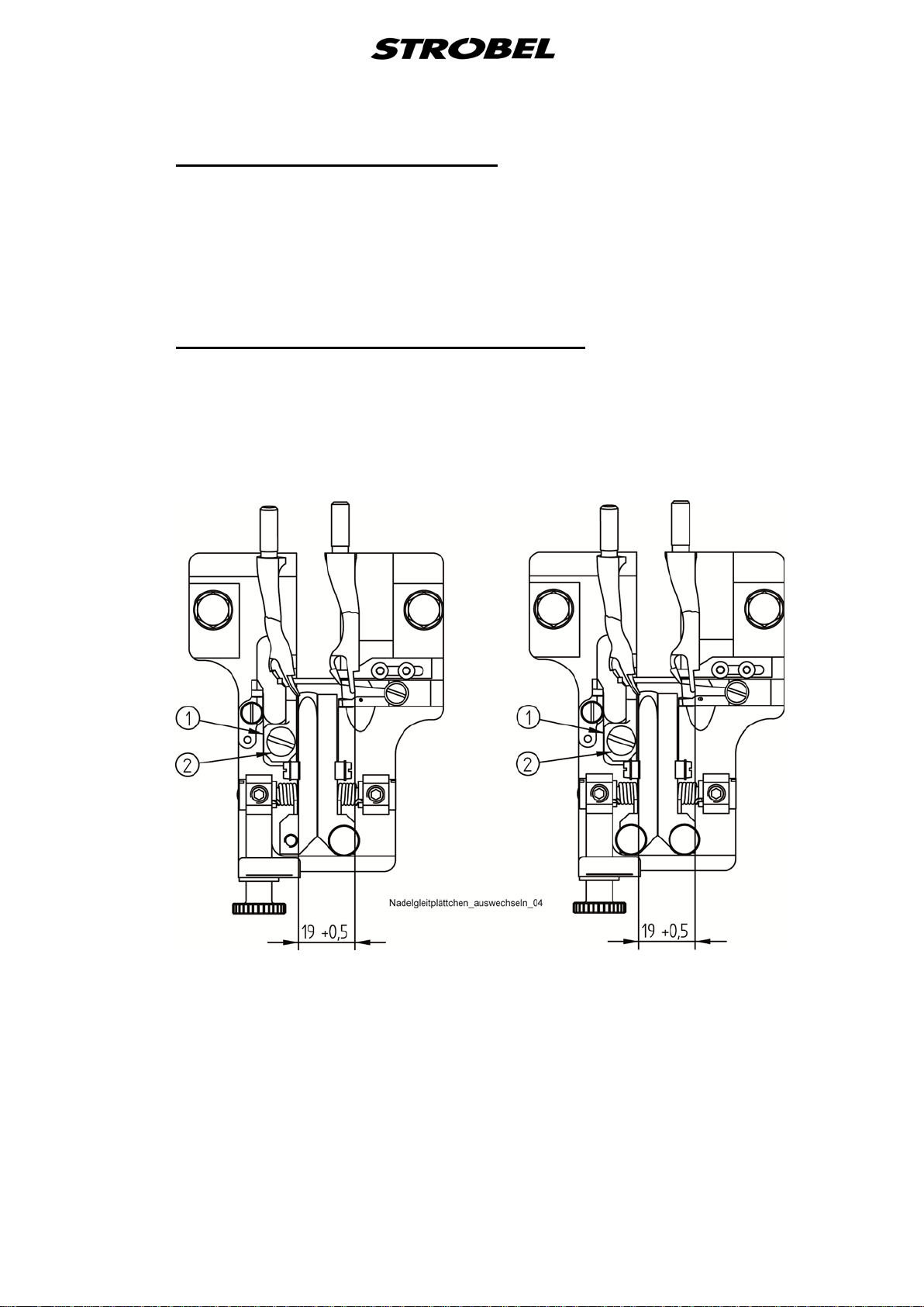
Replacing the needl e glide plate (Fi g. 3)
Loosen screw (2) to remove the needle glide plate (1). When re-mounting the
needle glide plate make sure that it fits closely to the needle plate bridge.
Fig. 3
VEB200-1 VEB200-2
12 MA_VEB200-1-2_A2_181015_en
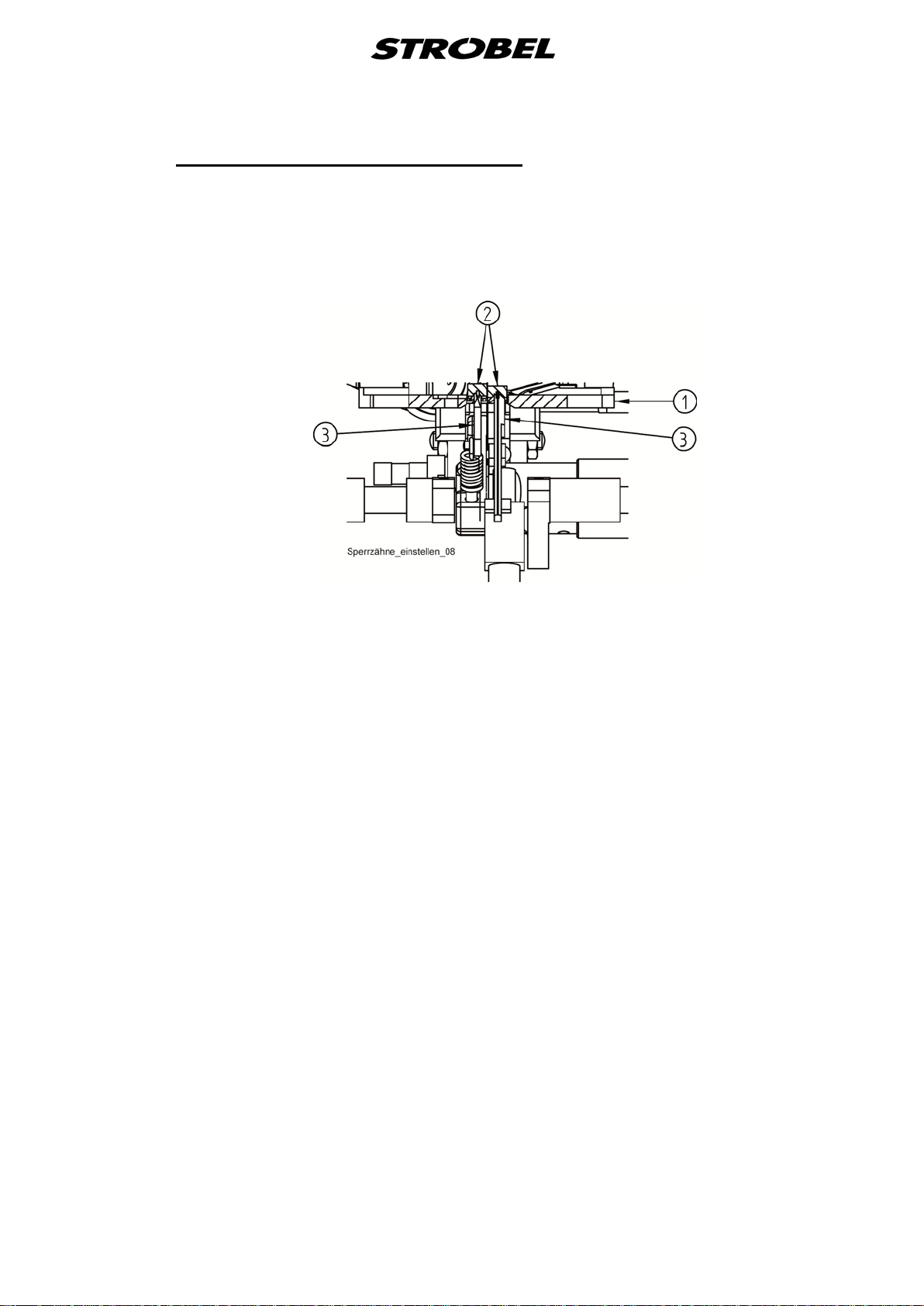
3.1.5
Setting the cloth retainers (Fig. 4)
After replacing the needle plate (1) check if the cloth retainers (2) are placed
centrically on the plungers (3). If necessary, displace the cloth support arm
axially.
Fig. 4
On the Kl.VEB200-1 both cloth retainers are feathered.
The pressure of about 4N left and 4N right is set by the bushes (5) (Fig. 2).
On the Kl.VEB200-2 both cloth retainers are feathered and combined with a
setting screw (4) (Fig. 2) that limits the cloth retainer lift to the top.
Basic setting for the pressure of the two cloth retainers about 4N. When setting
the cloth retainer lift, the pressure changes.
This combination is called plunger stopper, but can be used only in combination
with feathered plungers.
Plunger stopper and feathered plunger prevent that outer seams of the sewing
material are punctured during the sewing across cross-seams and other
thickenings and undesired markings become visible.
13 MA_VEB200-1-2_A2_181015_en
 Loading...