

Page 1

For the professional user
Für den professionellen Anwender
Betriebsanleitung
Class:
Klasse:
Model:
Ausführung:
Dated:
Stand:
VEB100-7
4
Operating Instructions
Spezialmaschinen GmbH
Page 2

Im Zeichen der Qualität
ou nd the Strobel trademark on every Strobel
machine leaving our works. And with good reason.
This symbol is a guarantee of the high quality of
our products. Quality which creates trust – trust
in our technology, our service and, not least of all,
in our good name.
ie nden die Strobel-Schutzmarke auf jeder
Strobel-Maschine, die unser Werk verlässt.
Und das aus gutem Grund. Denn dieses Zeichen
garantiert Ihnen die hohe Qualität unserer
Produkte. Qualität, die Vertrauen schafft – in unsere
Technik, unseren Service und nicht zuletzt in unseren
guten Namen.
S
Y
The sign of quality
Page 3

trobel clients know that they can expect a particularly
high standard of performance from our company and our
machines. Now you have settled for one of our products.
For us this is a source of encouragement and of obligation
to Justify your trust.
If you wish to prot from the performance and efciency of
your Strobel machine as long as possible, exact handling
and thorough care is necessary. For this reason we kindly
request that you read the operating instructions closely.
It provides all the information you need for trouble free
operation.
And if you do happen to need a spare part the enclosed
spare parts list gives a complete overview. It is clearly
classied according to components so that you can nd the
required part quickly and easily. In order to avoid errors we
request you to quote machine class, machine number and
part number completely on your spare part order.
We wish you lots of success in your work with your new
Strobel machine.
S
A decision with future
Spezialmaschinen GmbH
Page 4
Page 5

1 BA_VEB100-7_A4_180618_en
Operating instructions
STROBEL Class VEB100-7
Contents
1 General notes on safety ............................................................................................ 3
2 General ..................................................................................................................... 5
2.1 Operating instructions ..................................................................................... 5
2.2 Class identification, serial number and orientation of the machine ................. 5
2.3 Range of applications ..................................................................................... 5
2.4 Technical data ................................................................................................ 6
3 Installation and putting into service ........................................................................... 8
3.1 Unpacking the machine (Fig. 1) ...................................................................... 8
3.2 Installation (Fig. 2) .......................................................................................... 8
3.3 Sense of rotation .......................................................................................... 11
3.4 Motor drive using tooth belts ......................................................................... 11
3.4.1 Tension of toothed belt (Fig. 3) ........................................................ 11
3.4.2 Machine positions (Fig. 4) ................................................................ 12
3.5 The feed (Fig. 5 and Fig. 6) .......................................................................... 13
4 Instructions for use .................................................................................................. 15
4.1 Needles and threads .................................................................................... 15
4.2 Inserting the needle ...................................................................................... 15
4.3 Threading and straight grain ......................................................................... 16
4.4 Thread tension .............................................................................................. 17
4.5 Thread take-up lever .................................................................................... 17
4.6 Stitch depth regulator ................................................................................... 17
4.6.1 Setting the stitch depth .................................................................... 17
4.7 Cloth retainer ................................................................................................ 18
4.8 Sewing material transport ............................................................................. 19
4.8.1 Adjusting the stitch length ................................................................ 19
4.8.2 Adjusting the top feed ...................................................................... 20
4.9 Sewing drive ................................................................................................. 20
Page 6

2 BA_VEB100-7_A4_180618_en
5 Operating the machine ............................................................................................ 21
5.1 Switching on ................................................................................................. 21
5.2 Placing and removing the fabric - sewing process ........................................ 21
5.3 Sewing belt loops ......................................................................................... 22
5.3.1 Setting stitch depth and thread tension ............................................ 23
5.4 Quick hemmer changing device ................................................................... 24
5.5 Setting the hemmer ...................................................................................... 26
5.6 Fusible tapes ................................................................................................ 27
5.7 Cutting system .............................................................................................. 28
5.7.1 Sewing material ................................................................................ 28
5.7.2 Tape feed ......................................................................................... 28
5.7.3 Setting the cutting width ................................................................... 28
5.8 Pressing unit ................................................................................................. 30
5.8.1 General ............................................................................................ 30
5.8.2 Switch on the pressing unit (Fig. 17) ................................................ 32
5.8.3 Temperature setting (Fig. 20) ........................................................... 32
5.8.4 Inserting the sewn belt loop (Fig. 17) ............................................... 32
5.8.5 Interruption of the sewing process ................................................... 33
5.8.6 Selection of temperature and steam quality ..................................... 33
5.8.7 Belt loop guide ................................................................................. 33
5.8.8 Switching off the pressing unit ......................................................... 33
5.9 Problems during sewing and possible solutions ........................................... 34
6 Machine maintenance ............................................................................................. 37
7 Variable sewing tools .............................................................................................. 37
8 Optional parts .......................................................................................................... 39
8.1 Digital display 392.0637 ............................................................................... 39
8.2 Hemmer ........................................................................................................ 39
Subject to change without prior notice
Page 7

3 BA_VEB100-7_A4_180618_en
1
Every person in charge of setting up, operating, servicing and repairing the
machine must first read and understand the operating instructions and
particularly the safety instructions before starting up the machine.
General notes on safety
Failure to comply with the following safety instructions can lead to bodily
injury or damage to the machine.
1. The machine must only be operated by persons familiar with the relevant
operating instructions and who have been instructed accordingly.
2. Before commissioning also read the notes on safety and the operating
instructions of the sewing drive manufacturer.
3. Only use the machine in the intended manner and never without the
provided guards. Always observe the pertinent safety regulations.
4. Switch off the main switch or pull the power plug for threading, changing
the reels, exchanging sewing tools such as needle, gripper, needle plate,
transport devices, possibly cutter and cutting block, for cleaning and when
leaving the workplace as well as for maintenance.
5. General maintenance tasks may be carried out only by properly trained
persons in accordance with the operating instructions.
6. Repair work, retrofitting and maintenance may be carried out only by
technicians or specially trained personnel.
7. When servicing or repairing pneumatic equipment, the machine must be
disconnected from the pneumatic supply. Exceptions are only allowed for
adjustment work and tests of functionality performed by specially trained
technicians.
8. Only specially qualified technicians may work on the electrical equipment.
9. It is forbidden to work on electrically live components! Exemptions are
covered by the EN50110 (DIN VDE0105) regulations.
10. Any retrofitting or alterations to the machine may only be performed under
strict compliance with all pertinent safety regulations.
11. Only use our approved spare parts when servicing and/or repairing the
machine.
12. It is forbidden to operate the sewing head until it is determined that the
entire sewing unit complies with EU provisions.
13. It is essential that you observe and follow these instructions as well as the
generally valid safety regulations.
Page 8

4 BA_VEB100-7_A4_180618_en
14. Warning instructions given in the operating instructions that pertain to
especially dangerous parts of the machine must be indicated at these
positions using a safety symbol.
Warning instructions given in the operating instructions that pertain to
special injury hazards for operating personnel or technicians must be
indicated at these positions using a safety symbol.
Page 9

5 BA_VEB100-7_A4_180618_en
2
2.1
General
Any person involved in the installation, operation, maintenance and repair of
the machine must have read and understood the operating instructions and
mainly the safety instructions before starting the machine.
Operating instructions
2.2
The operating side of the machine is the basis for descriptions referring to
sides.
The class identification (type) as well as serial and model number (after the
dash) are located on the rear side of the housing.
Class identifi c a t ion, serial numbe r and orientation of t he
machine
2.3
Class VEB100-7 is suitable for sewing belt loops from waste fabric.
The cutting device trims the material automatically to the size for the 9.5 and
11 mm hemmer.
The supply of the sewing materials occurs by means of tape feed.
Range of applications
The integradet pressing unit presses the belt loops.
The steam can be supplied either by means of a central steam generating unit
with interconnected solenoid valve box including condenser and steam trap or
by means of a steam generator.
The range of applications of the different machines can be extended by
exchanging the variable sewing tools, i.e. that other fabric qualities than the
above mentioned ones can be sewn as well.
Variable sewing tools please see point 7.
Page 10

6 BA_VEB100-7_A4_180618_en
2.4
Recommended rated speed 1800 min-1
Technical data
Motor power 550 W
Toothed belt pulley/machine Z = 38
Toothed belt profile HTD 5M-9
Stitch length 3 - 6 mm
(depend on fabric)
Kind of stitch single thread chainstitch blindstitch
Stitch type 103
Needle system GROZ-BECKERT 1669 EEO
Needle size 90
Thread polyester continuous filament
Thread size 120/2
Pneumatic connection 3 - 6 bar
Average air consumption 2,5 m³/h (without suction)
Suction average air consumption 20 m³/h
Required space 0.7 m x 1.1 m
Pressing unit
Current voltage 230 V single phase alternating
Heating capacity 1.68 KW
Total connected load 1.80 KW
Temperature range 60 - 240°C
Heating up time approx. 10 min.
Working pressure:
Steam 2.5 - 5 bar
Pneumatics 3 - 4.5 bar
Pneumatics suction 5 - 6 bar
Feed length per revolution self-regulating
Operating noise:
Medium sound pressure level
at a speed n = 1800 min-1 LpAm 72 dB(A)
Noise test according to DIN 45635-48-1 KL3
Page 11
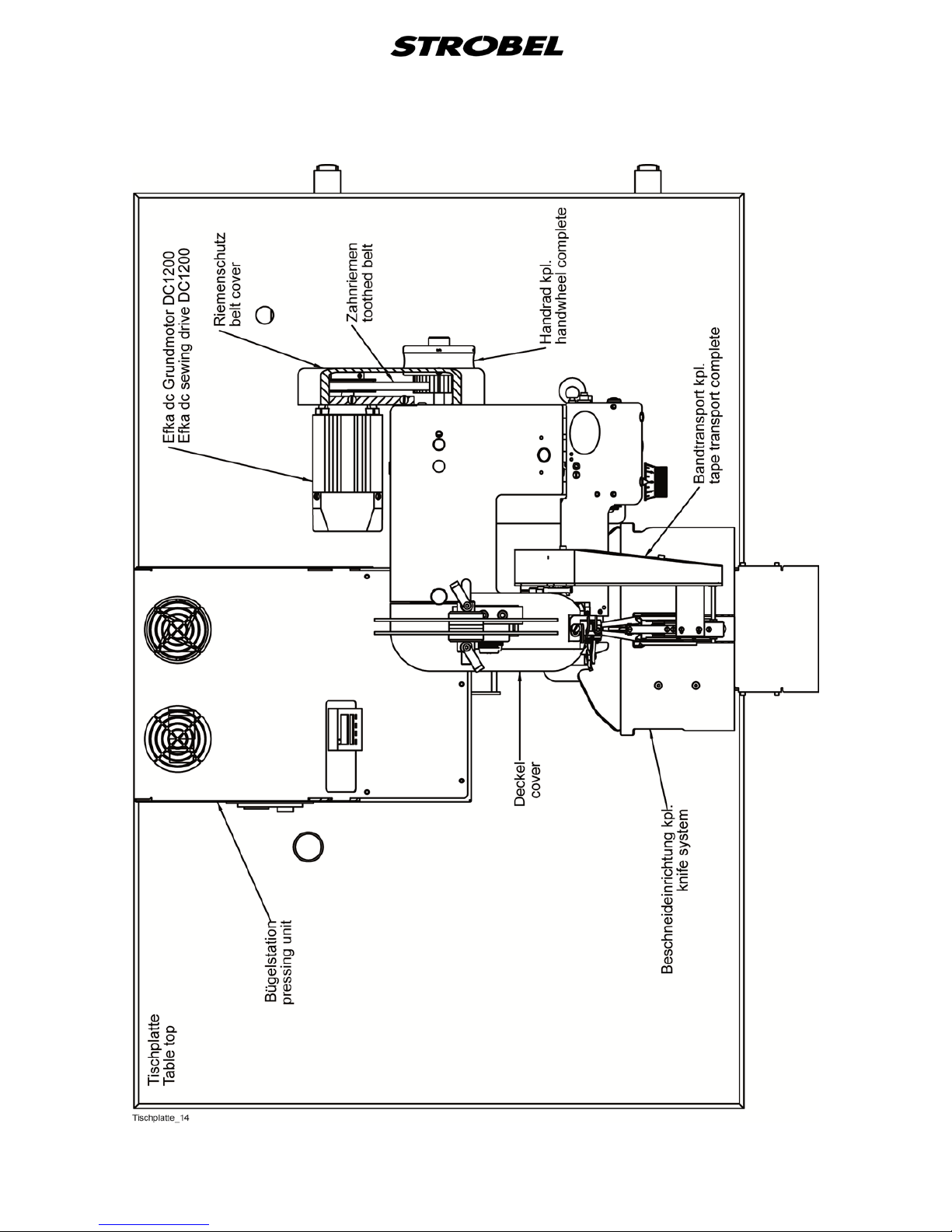
7 BA_VEB100-7_A4_180618_en
Fig. 1
Page 12
8 BA_VEB100-7_A4_180618_en
3
3.1
Installation a nd put t ing into service
If the pressing unit is supplied together with a Class VEB100-7 it is screwed
onto the table top behind the blindstitching machine.
Unpacking the machine (Fig. 1)
Make sure that all accessories have been unpacked before throwing away any
packing material.
3.2
Installation (Fig. 2)
CAUTION! Danger of injury!
Danger of bodily injuries or finger bruises through pulling in
of garments or hairs! The machine may not be operated
without belt guards for head and motor.
Make sure that all screws on the stand are tight and retighten them, if
necessary.
Attention!
Before putting the machine into service make sure that the
electric connecting data on the motor’s name plate, mainly
voltage and frequency, correspond to your electric network.
All rust protection agents, such as Vaseline and similar agents have to be
wiped off carefully from the sewing tools before putting the machine into
service.
Page 13
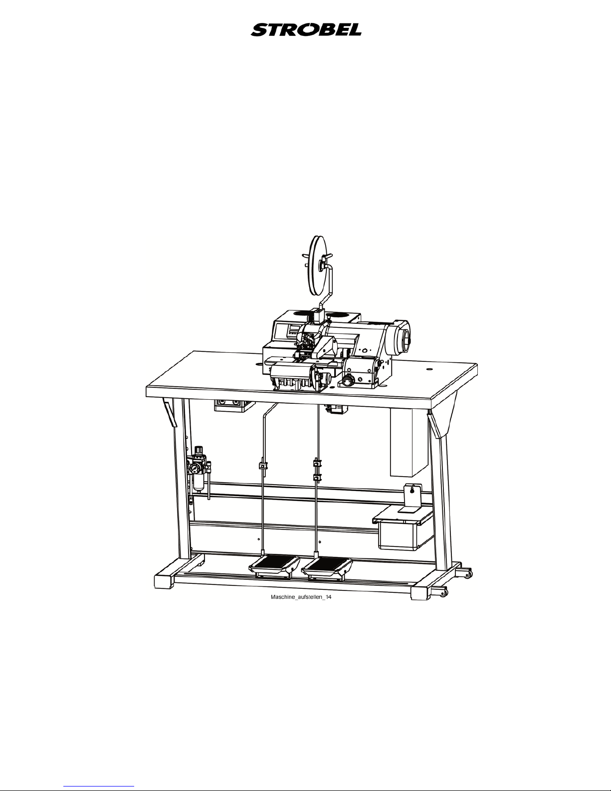
9 BA_VEB100-7_A4_180618_en
Fig. 2
Page 14
10 BA_VEB100-7_A4_180618_en
Pressing unit:
The pressing unit has to be connected to an additional central steam unit with
interconnected solenoid valve or to a steam generator.
Attention: To avoid condensation water it is recommended to use a short
teflon hose (approx. 2.5 m max.) with small diameter. And the
hose should not sag to avoid that condensation water is collected.
The steam quantity should be reduced or adapted to the needs by means of a
manual valve.
Check all screws and re-thighten them, if necessary.
Attention!
Before putting the pressing unit connected to a sewing
machine into service all connecting data such as current,
working pressure, steam, pneumatics have to be checked
comparing them with the values shown in the operating
instructions and the type plate.
Page 15
11 BA_VEB100-7_A4_180618_en
3.3
The correct sense of rotation of the hand wheel is clockwise in line of vision on
the hand wheel.
Sense of rotation
3.4
3.4.1
Motor drive using tooth belts
Tension of toothed belt ( Fig. 3)
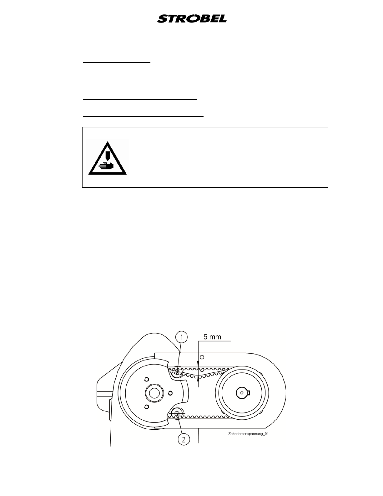
CAUTION! Danger of injury!
Switch off the machine at the mains when checking the
belt tension. Do not operate the machine without belt
guard. Otherwise DANGER of crushing fingers, of
injuries to the body or of pulling in of part of clothing.
The toothed belt should not be tensioned too much. You should be able to
compress it with light thumb pressure by about 5 mm.
Too little or too tight toothed belt tensioning can impair the positioning of the
machine and therefore impair the function sequence.
Tensioning the toothed belt (Fig. 3):
- Release the upper and the bottom retaining screw (1), (2) at the upper
part of the machine.
- Pull out the motor slightly and tighten the bottom retaining screw (2)
slightly.
- Tension the toothed belt by swivelling the motor.
- Tighten the upper and the bottom retaining screw (1), (2) again.
Fig. 3
Page 16
12 BA_VEB100-7_A4_180618_en
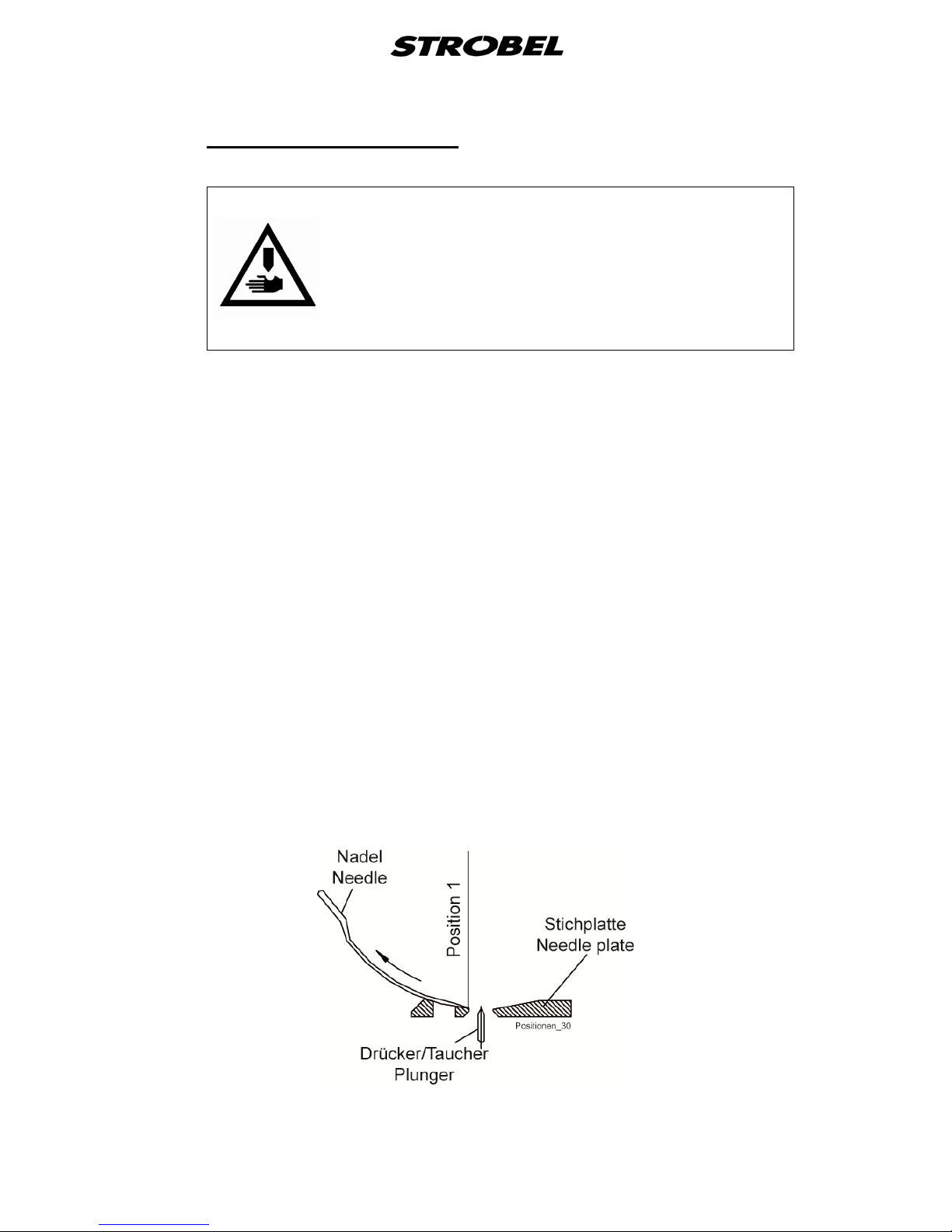
3.4.2
Machine positions (Fig. 4)
CAUTION!. Danger of injury!
Entanglement hazard for clothing or hair and danger of
finger injuries and needle punctures! When checking the
positions while the machine is turned on, keep your
fingers and hands away from moving parts.
General:
The machine requires a needle position and depending on the sewing drive,
possibly also a reference position.
Reference position:
The reference position must be set in such a way, that the point of the
needle in direction of the insertion stitch closes with the right (inner) edge
of the needle slide plate.
Notes for sewing drives which have two needle positions:
The above mentioned needle position is position 2 at the sewing drive.
It is essential that position 1 is set with consultation of the operating
instructions of the sewing drive
Needle position (when stopped within the stitch):
The needle position must be set so that the tip of the needle closes
against the right edge of the needle slide plate facing towards the outward
stitch.
At the same time, the thread loop lies under tension across the looper.
The needle position is position 1 at the sewing drive.
Fig. 4
Page 17
13 BA_VEB100-7_A4_180618_en
3.5
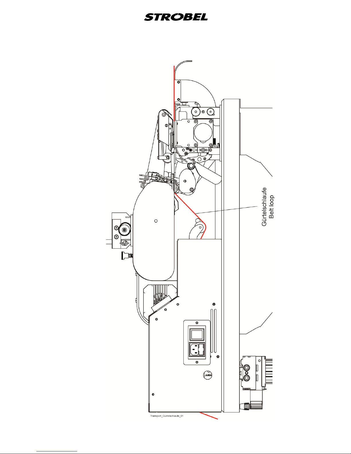
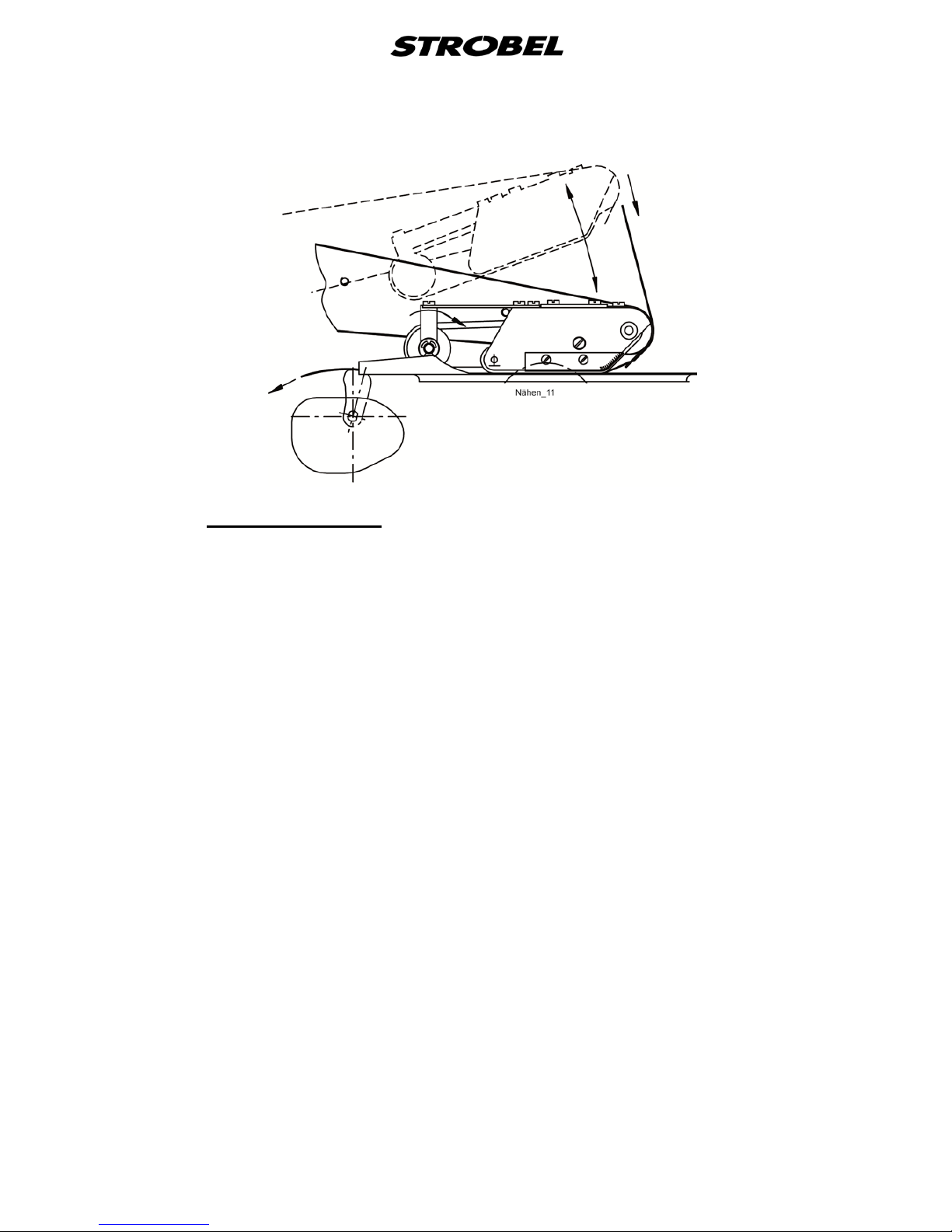
- The transport or the speed of the pressing unit is controlled automatically
by the deflector roll (
The feed (Fig. 5 and Fig. 6)
Fig. 5) (1). (see also “4.8.1 Adjusting the stitch
length“)
- After the needle plate, the loop of the belt has to be routed through
underneath the deflector roll before it is fed into the opening of the
pressing unit. If the belt loop is not routed underneath the deflector roll,
the transport cannot be controlled automatically, which leads to transport
problems. (Fig. 6)
Fig. 5
Page 18
14 BA_VEB100-7_A4_180618_en
Fig. 6
Page 19
15 BA_VEB100-7_A4_180618_en
4
4.1
Instructions for us e
The sewing quality can be influenced to a considerable extent by choosing the
most suitable needles and threads for the material to be sewn. It is
recommended to use controlled GROZ-BECKERT needles system 1669 EEO
only.
The machine is supplied with size 90 needles.
Needles and threads
Notice: A perfect needle is of great importance for a good sewing result.
Damages of the needle point which often can be made visible under
a magnifier only may deteriorate the sewing result. Replace the
needle in time!
We recommend twisted polyester filament threads of size 120/2 respectively.
Because of their high strength and ability to slide, combined with a low volume
they are to be preferred over a spun thread.
Guaranteed remark!
This machine has been set and sewn off with genuine
GROZ-BECKERT needles.
No guarantee can be granted if the settings are modified
for using different needle types.
4.2
Inserting the needle
CAUTION! Danger of injury!
Switch off machine electrically and confirm that the
machine is really in standstill position by operating the
treadle for the motor control before changing the needle.
Otherwise danger of finger bruises and needle
throughstitches.
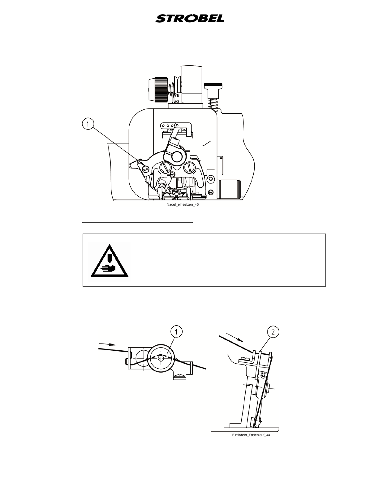
The curved needle shape determines its position in the needle lever. Attention
should be paid only to ensure that the needle piston is pushed to the stop in the
channel of the needle lever and that the screw (1) Fig. 7 of the needle clamping
plate is tightened well.
Page 20
16 BA_VEB100-7_A4_180618_en
Fig. 7
4.3
Threading and straight grain
CAUTION! Danger of injury!
Switch off machine electrically and confirm that the
machine is really in standstill position by operating the
treadle for the motor control before threading. Otherwise
danger of finger bruises and needle throughstitches.
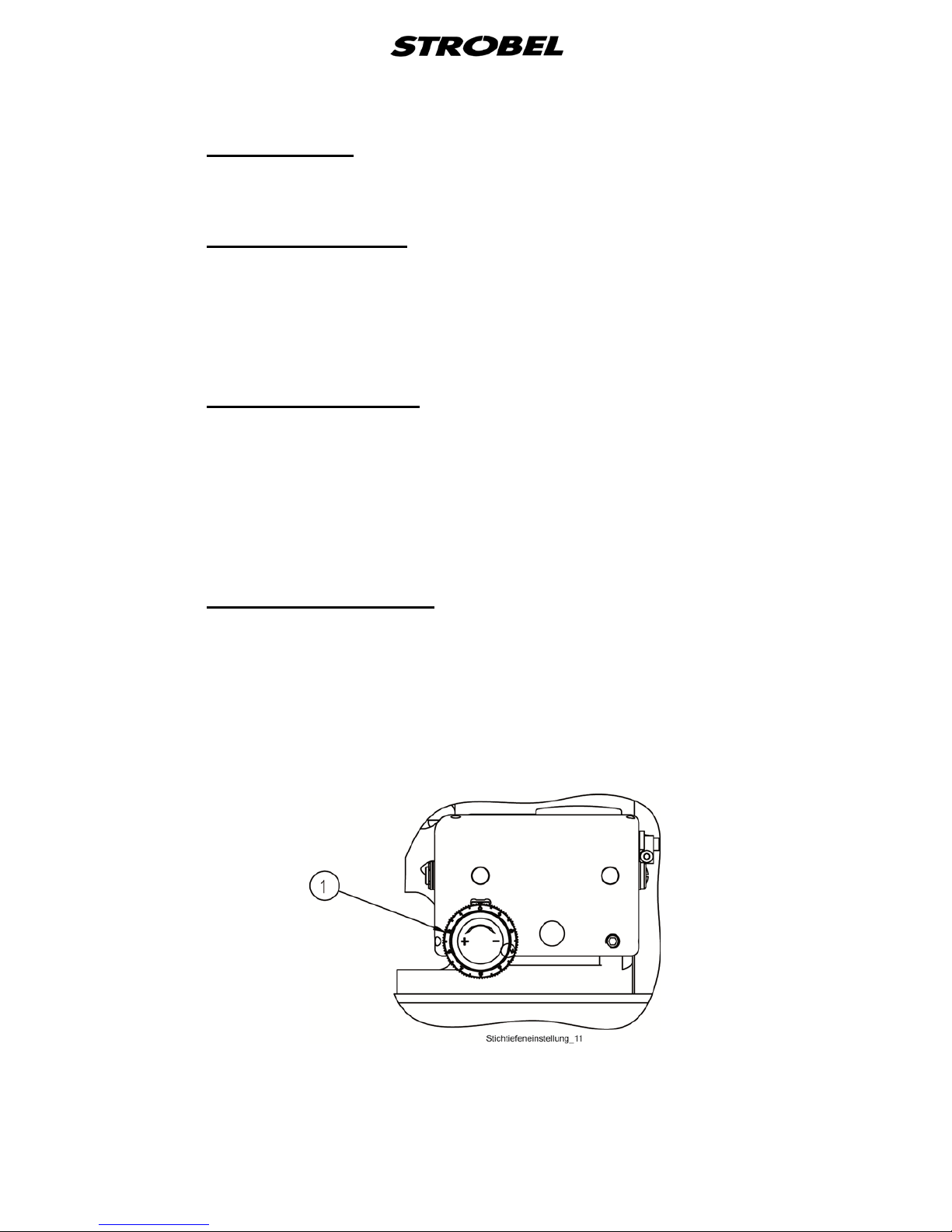
Fig. 8 shows the correct threading by using the thread take-up.
Fig. 8
Page 21
17 BA_VEB100-7_A4_180618_en
4.4
Depending on thread and fabric quality, nature and thickness the thread tension
is set by tension nut (1) (
Thread tension
Fig. 8).
4.5
The thread take-up lever (2)
Thread take-up lever
Fig. 8 avoids thread twist and turning over of the
loop, thus enabling a secure taking up of the loop by looper and needle. There
is a uniform stitch formation.
The function of the thread take-up lever is influenced by the thread course
(choice of the eyelet).
4.6
By means of the stitch depth regulator you can adjust the distance between the
upper edge of the plunger and the needle radius, i.e. the distance the plunger is
lifted or lowered depending on the material thickness. This determines the
depth the needle penetrates the fabric layers hold between plunger and
hemmer. This value is called stitch depth.
Stitch depth regula t or
A low stitch depth can result in skip stitches, if the stitch depth is too deep the
needle can stitch through the material.
4.6.1
The stitch depth is set by means of the adjusting knob (1) at the front side of
the machine (
Setting the stitch depth
Fig. 2).
Turning the adjusting knob to the left (+) means deeper needle penetration.
Turning the adjusting knob to the right (-) means lower needle penetration.
Per notch the stitch depth is altered by 0,005 mm.
Fig. 9
Page 22
18 BA_VEB100-7_A4_180618_en
4.7
Cloth retainer
Attention!
Danger of finger bruises through unintended actuation of
the treadle during setting works in the needle plate area.
The machine has no real cloth retainer. During the time of needle penetration
the material is hold between hemmer and plunger.
The pressure of the hemmer on the fabric layers should be as low as possible
to avoid any twist or marks.
This is of main importance for delicate fabrics such as e.g. velvet.
The hemmer should be set in a way that the fabric cannot move during needle
penetration.
This setting is of great importance with regard to the sewing quality!
See also point “0 When the hemmer is exchanged, the height of the hemmer in
relation to the curved knife needs to be checked and adjusted if necessary.
Turn the knurled screw (1) for this until the correct setting has been made.
Setting the hemmer”.
Page 23
19 BA_VEB100-7_A4_180618_en
4.8
The machine transports the sewing material using a rigid upper transport. The
feed (stitch length) can be set from 3 - 6 mm in 4 steps. Serially, a pyramidtoothed feed dog is mounted, which can be exchanged for a saw-toothed one if
necessary. (see point „
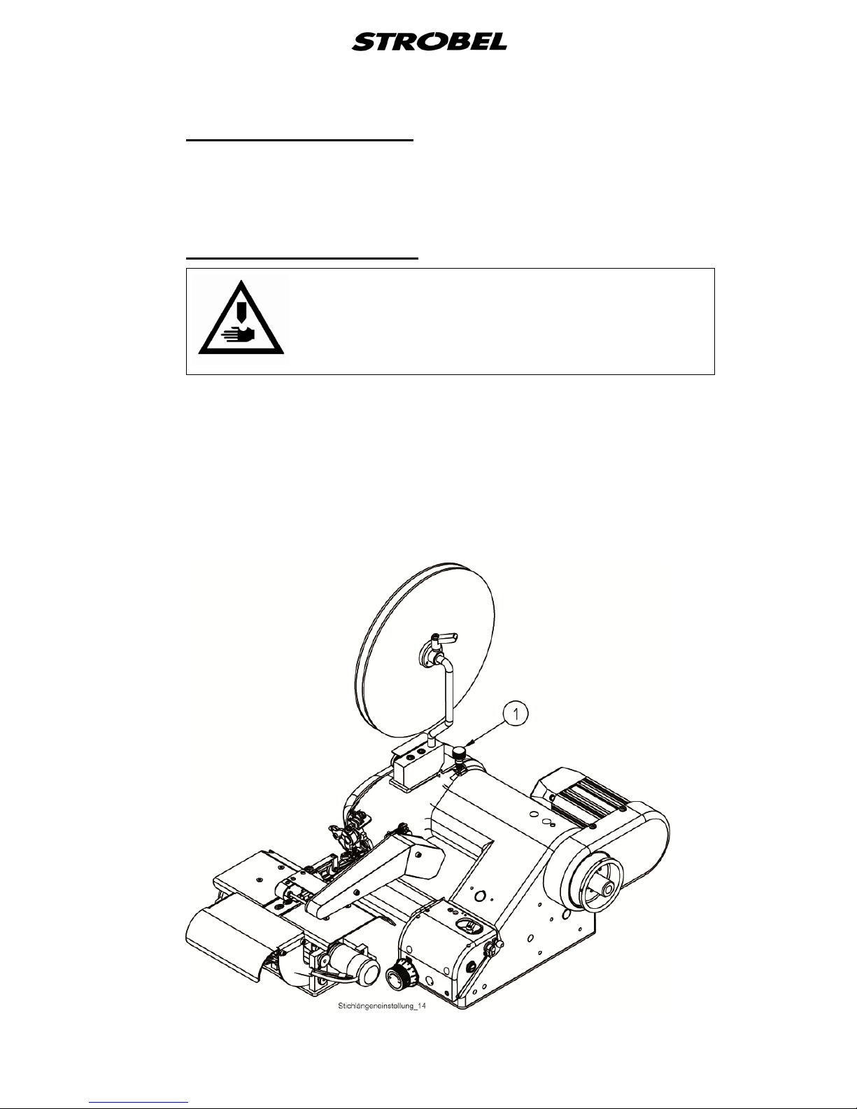
Sewing material transport
7 Variable sewing tools“).
4.8.1 Adjusting the stitch length
CAUTION!
Switch off the machine and compress the motor switch
pedal to ensure that the machine is truly switched off.
- Press the stitch setting knob (1) (Fig. 10) and turn the handwheel until it
simply snaps into place. The configured stitch length corresponds to the
number engraved in the handwheel as it comes to a standstill in the
highest position. Press down the setting knob and move the handwheel
forwards until the desired stitch length noticeably snaps into place.
See also point “3.5 The feed (Fig. 5 and Fig. 6)”.
Fig. 10
Page 24

20 BA_VEB100-7_A4_180618_en
4.8.2
The transporter can be adjusted in its intrusion depth to the needle plate by
loosening the two fastening screws. If the stitch length is adjusted across a
greater range e.g., from 6 to 3 mm, then the feed dog should be readjusted.
Adjusting the top feed
Adjustments might also be required when changing to sewing materials that are
thicker or otherwise different in quality.
Here, observe the instructions given in the mechanic's manual.
4.9
Please observe the operating instructions of the sewing drive supplied with the
machine where you will find instructions to program the control and the motor
speed.
Sewing dr ive
On programmable sewing drives the maximum speed can be set electrically.
Page 25
21 BA_VEB100-7_A4_180618_en
5
Operating the mac hine
CAUTION! Danger of injury!
Please observe the sewing area carefully during sewing.
Otherwise danger of finger bruises and needle
throughstitches.
5.1
Connect the compressed-air conditioner to the compressed air supplier
(10 bar) or to the compressor and set it to 3 - 4 bar.
Switch on the control and the pressing unit at the respective I/0 switch.
Switching on
5.2
The cloth support arm is lifted by pressing the left hand treadle.
Placing and removing t he f a bric - sewing process
The machine starts sewing by operating the right hand treadle.
The machine runs at maximum speed when the right hand treadle is completely
pressed down.
By operating the right hand treadle the trimming motor starts as well. It runs at a
constant speed (trimming speed) independent of the sewing drive.
Swing up the tape feed. Guide the tape through the back guide of the tape feed
into the hemmer. Lower the tape feed and feed the fabric towards the tape
(Fig. 11). By operating the right hand treadle the fabric is now guided through
the hemmer and a belt loop is sewn. The feed dog catches the sewn belt loop
from above and pulls it forward.
Make sure that no clue is formed behind the needle plate.
Cut an endless belt loop wherever required. The cloth support arm has not
necessarily to be lifted (left treadle).
Guide the belt loop behind the needle plate under the roll from the material
guide (1) (Fig. 5) to the pressing device.
Page 26
22 BA_VEB100-7_A4_180618_en
Fig. 11
5.3
There is a number of hemmers available to sew nearly all required fabrics. In
general, the belt loops are sewn of the waste fabrics of the trouser production.
Sewing belt loops
In the hemmer the fabric is symmetrically folded and centrically blindstitched.
Using a tape facilitates the sewing and reinforces the belt loop.
The correctly cut fabric is guided to the hemmer manually. The required fabric
width depends on the hemmer size. Depending on the fabric quality, usually the
cut material should be approx. 3 times as wide as the sewn belt loop:
e.g. hemmer size 9.5 - material width = 28.5 mm
The tape is first manually pushed through the bow at the hemmer into the
hemmer. As soon as the feed dog has caught the tape or the sewn belt loop an
endless belt loop can be sewn by just placing the next fabric under the previous
one. Make sure that the fabric enters the hemmer centrically.
Page 27
23 BA_VEB100-7_A4_180618_en
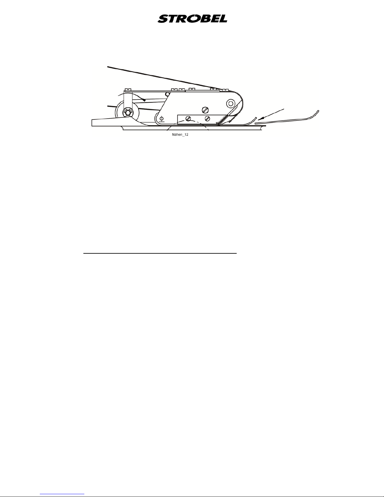
Fig. 12
Attention: very fuzzy fabrics may disturb the process.
The cuttings fall down into a garbage chute. The material is trimmed exactly
and then guided to the hemmer.
The tape is manually pushed through the bow at the swivelled down tape
feeding device and then through the hemmer’s bow into the hemmer. Now the
tape can be further fed to the needle by means of the knurled disk (Fig. 12). As
soon as the feed dog behind the needle plate has caught the tape, the
production of the belt loop can be started. The material is fed to the tape
feeding device along the limit stop on the right support plate.
If no tape or a very thin tape is used the belt loops should be sewn
“overlapping” to ensure that the material in the hemmer pulls the next fabric.
5.3.1
Set the stitch depth in a way that the tape is throughstitched and the outer
fabric is blindstitched.
Stitch depth regulation see also point “
Setting stitch dept h a nd t hread tension
4.6 Stitch depth regulator”.
Set the thread tension in a way that the left and right folded fabric side butt
without overlapping.
(Thread tension see point “4.4 Thread tension”)
Page 28
24 BA_VEB100-7_A4_180618_en
5.4
Quick hemmer changing device
CAUTION! Danger of injury!
When working on the cutting system, switch off the power
to the complete machine. Otherwise there is a danger of
fingers getting crushed or cut!
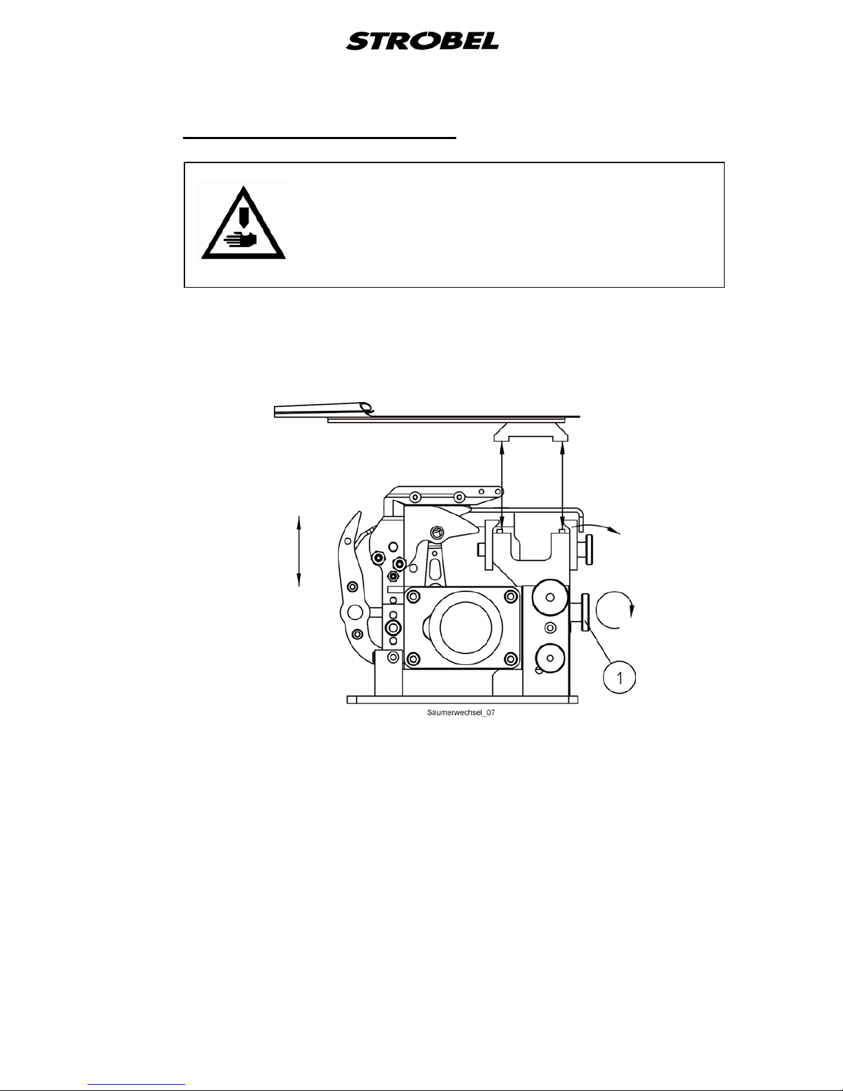
The hemmers are screwed to a holder and were set at works. The quick
hemmer changing device facilitates the hemmer replacement within one
hemmer size (width) without the necessity of re-adjusting it. (Fig. 13).
Fig. 13
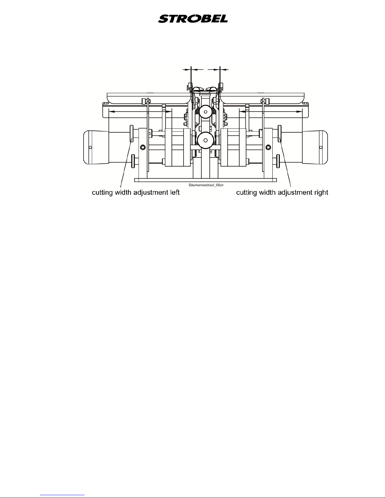
When changing the hemmer width the left and right supporting plates have to
be adjusted (Fig. 14).
Page 29
25 BA_VEB100-7_A4_180618_en
Fig. 14
When the hemmer is exchanged, the height of the hemmer in relation to the
curved knife needs to be checked and adjusted if necessary.
Turn the knurled screw (1) for this until the correct setting has been made.
Page 30
26 BA_VEB100-7_A4_180618_en
5.5
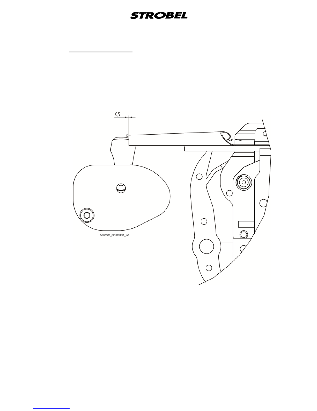
The hemmer lies on the plunger with the belt loop folded on one side already,
i.e. that the fabric is hold for the needle penetration and the set stitch depth is
ensured. Therefore the hemmer is slotted at the front part.
Setting the hemmer
The hemmer’s outlet should be approx. 0.5 mm in front of the needle plate
(Fig. 15).
Fig. 15
Page 31
27 BA_VEB100-7_A4_180618_en
5.6
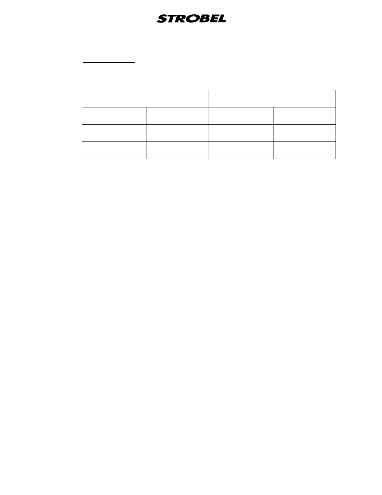
It is recommended to provide the belt loops with a fusible tape.
Choose the tape width according to the following chart:
Fusible tapes
hemmer size tape width
mm inch mm inch
9,5 3/8 8,5-9 5/16
11 7/16 10-10,5 3/8
Tapes of the most different qualities can be used.
Tapes coated on one side only or on both sides are used with the fabric when
pressing the ready sewn belt loop.
Caution: When fusible tapes with adhesive are used, be sure that no
adhesive residues can get stuck in the hot ironing station.
The belt loop should always be sewn overlapping or at least
without a gap.
Page 32
28 BA_VEB100-7_A4_180618_en
5.7
The cutting system with integrated quick hemmer changing device is mounted
to the table plate as the standard hemmer support.
The operation is supported by an additional tape feed (
Cutting system
Fig. 11).
The cutting system needs to be cleaned regularly.
See also point “6 Machine maintenance”
5.7.1
We recommend a minimal trimming width of at least 3 mm per side of the
sewing material to be sewn.
Sewing material
Suction
For the optional Suction, we recommend a maximum trimming width of
maximum 10 mm for each side of the sewing material.
Notice: The more stiff and inflexible the sewing material is, the lower the
trimming width should be, but not below the minimum trimming width.
5.7.2
The tape feed is pivoted in the machine head and is operated synchronously
with the machine’s upper feed.
When changing the hemmer, etc. it can be swiveled upwards. In normal
position it lies on the hemmer’s front part with a certain spring pressure and
feeds the material between the knives to the hemmer. To replace the toothed
belt screw off the cover on the left side. (
Tape feed
Fig. 12).
5.7.3
Setting the cutting width
CAUTION! Danger of injury!
When working on the cutting system, switch off the power
to the complete machine. Otherwise there is a danger of
fingers getting crushed or cut!
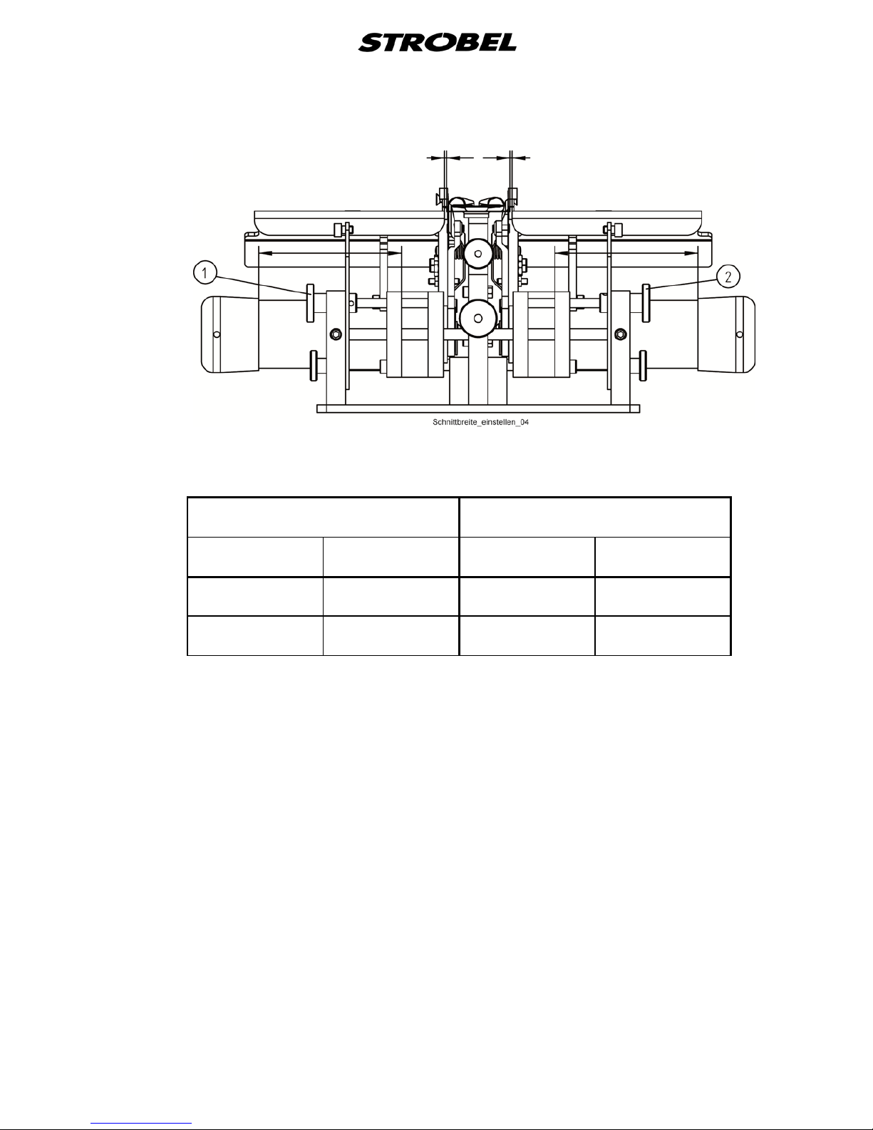
The cutting width is adjusted by the two upper left knurled nuts (1) and right (2)
on the cutting system. (Fig. 16).
Page 33
29 BA_VEB100-7_A4_180618_en
Fig. 16
Please use the following chart for the cutting widths at the knives’ cutting
edges:
hemmer size trimming width
mm inch mm inch
9,5 3/8 28,5 1 1/8
11 7/16 33 1 5/16
The trimming width can be set from 23 to 55 mm.
Page 34
30 BA_VEB100-7_A4_180618_en
5.8
Pressing unit
CAUTION! Danger of injury!
When working on the pressing unit, switch off the power to
the entire machine, disconnect the pneumatic supply and
allow the device to cool down. Otherwise there is a danger
of fingers getting crushed, scalding and electric shock!
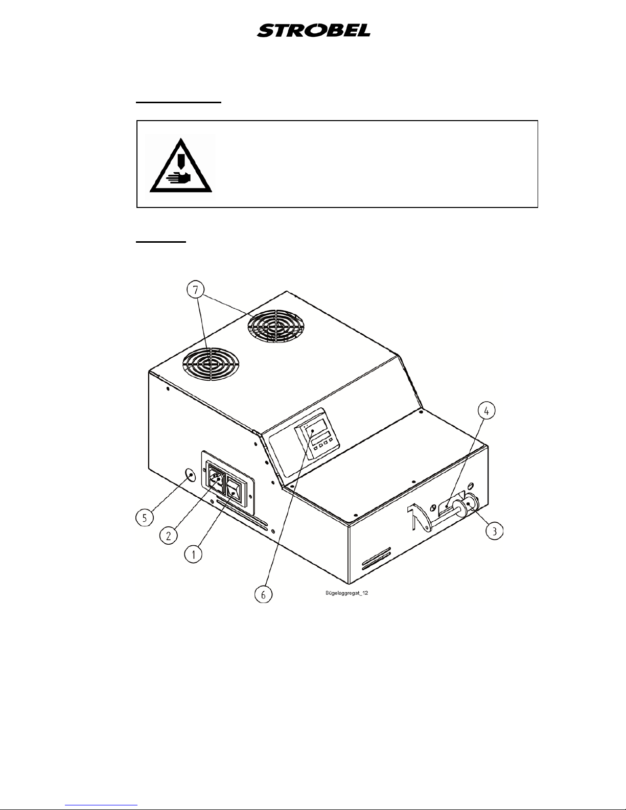
5.8.1
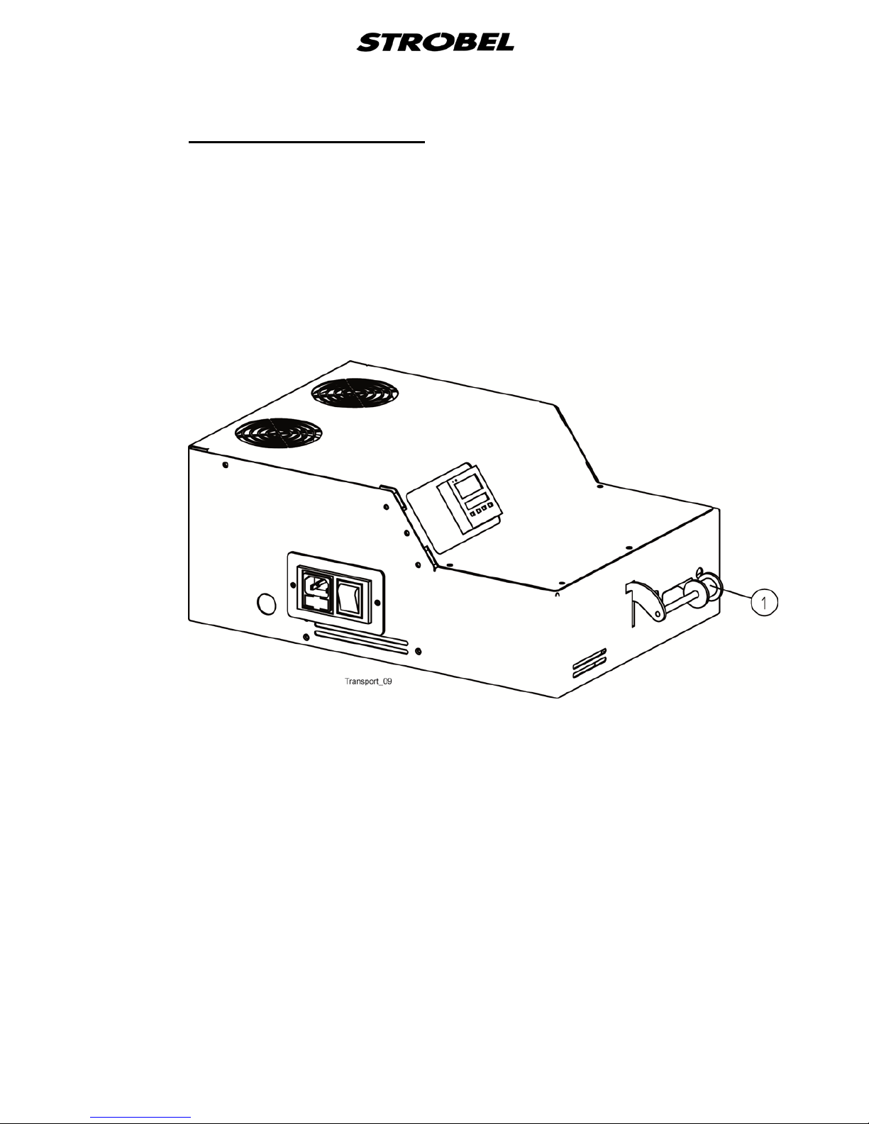
Fig. 17
General
1 I/0 switch
2 Electrical connection
3 Deflector roll
4 Belt loop inlet
5 Passage for pneumatic hoses
6 Temperature setting
7 Fans
Page 35
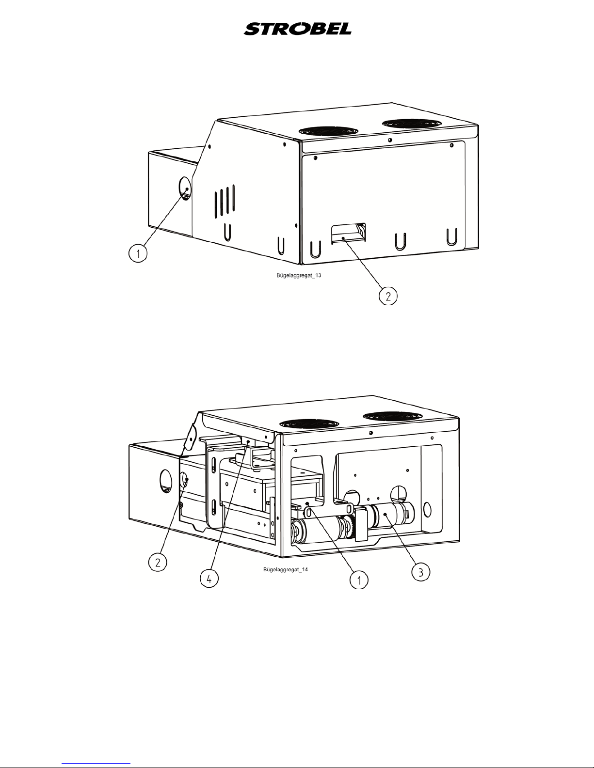
31 BA_VEB100-7_A4_180618_en
Fig. 18
1 Passage for steam connection
2 Belt loop outlet
Fig. 19
1 Blower connection
2 Steam connection
3 Step motor
4 Pneumatic cylinder
Page 36
32 BA_VEB100-7_A4_180618_en
5.8.2
Once the technician has duly mounted all air, steam and current connecting
cables the unit can be put into operation as follows:
Switch on t he pressing unit (Fig. 17)
The pressing unit itself is switched on at the pressing unit on the left side. The
pressing unit is ready once the set temperature is reached.
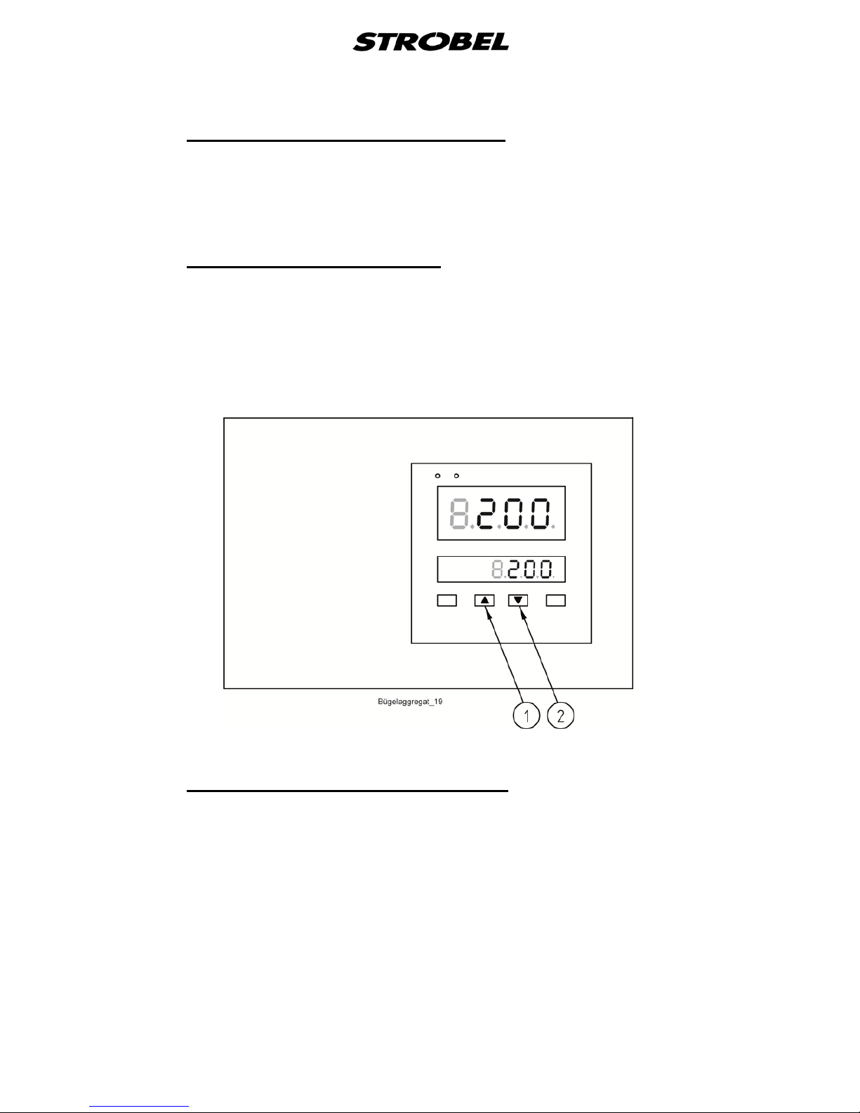
5.8.3
The desired temperature can be set at the temperature display by the two
arrows (up (1)/down (2)).
Temperature setting (Fig. 20)
The lower display shows the set/desired temperature.
The upper display shows the current temperature.
Fig. 20
5.8.4
1. Sew the belt loop long enough with the stitch upwards until about 5 cm
can be inserted into the pressing unit.
Inserting the sewn belt loop ( Fig. 17)
2. The loop of the belt has to be routed through “underneath” the deflector
roll (3) and fed into the opening of the pressing unit.
Caution: If the loop of the belt is NOT fed through underneath the
deflector roll, it is transported directly by the transport of the
pressing unit at maximum speed which can damage the belt
loop (stretch, rip, …). The deflector roll is responsible for the
automatically regulated transport.
Page 37

33 BA_VEB100-7_A4_180618_en
5.8.5
The ironing shoe is lifted when the sewing and ironing machine is switched on.
A built-in temperature regulator keeps the set temperature at about ±20 ºC
constant.
Interruption of t he se wing proces s
Please switch off the ironing device during longer interruptions of sewing with
I/0 switch (1) (as Fig. 17) at the control box for the ironing device.
Ironing material that remains between the hot lifted halves of the ironing unit
can be damaged for example by fine cloth fibres discolouring yellow or
becoming shiny. That depends however on the set ironing temperature.
5.8.6
To obtain a good pressing quality it is important to choose the right temperature
and steam quantity.
Selection of temperature and steam quality
if the temperature is too high: the material becomes shiny, delicate fabrics
are damaged; if adhesive tapes are used the
belt loops become hard after cooling down.
if the temperature is too low: condensation of water, water stains,
insufficient drying by compressed air, no or
bad conglutination if coated tapes are used.
too much steam: condensation of water, water stains,
insufficient drying by compressed air, too
much steam at the opening where the
material is positioned.
not enough steam: the material becomes shiny, bad pressing
quality.
5.8.7
When sewing without or with thin tapes (even coated tapes) it is necessary to
guide the belt loop under tension between sewing machine and pressing unit to
prevent the folded fabric edges from twisting which would result in a bad
pressing quality.
Belt loop guide
This could also be avoided by slightly penetrating the outer fabric layer with the
needle, however, when sewing delicate fabrics this results in marks and is
therefore not recommended.
5.8.8
After the pressing unit has been switched off, the ventilators continue to run
until a temperature of about 80 °C has been reached. To avoid damage, this
only works as long as the pressing unit is still connected to the mains.
Switching off the pressing uni t
Page 38
34 BA_VEB100-7_A4_180618_en
5.9
Problems during s ewing and possi ble solutions
CAUTION! Danger of injury!
Switch off machine electrically and confirm that the
machine is really in standstill position by operating the
treadle for the motor control. Otherwise danger of finger
bruises and needle throughstitches.
Thread tears
Possible reasons:
- sharp edges or grooves in the needle guide, thread take-up, looper
or needle eye after a long time of machine operation
- looper or loop stroke are not set correctly, therefore the thread loop
is not always caught
- thread tension set too high
- thread size does not correspond to needle size (thread is too thick)
Solutions:
- replace or polish the damaged parts
- re-adjust looper and/or loop stroke
- re-adjust thread tension, check thread course
- choose the correct thread size
Please observe: thread course, thread, needle plate with plunger and
cloth retainer, needle and thread tension should always
be set and chosen according to the material to be
sewn.
Inexact needle penetration
Possible reasons:
- worn out or damaged needle
- wrong setting of needle plate or needle guide
- damaged or worn out needle glide plate
- wrong needle size
- damaged plunger or wrong plunger setting
Solutions:
- replace damaged needle, choose suitable needle size
- check settings and re-set, if necessary
- replace needle glide plate
Page 39

35 BA_VEB100-7_A4_180618_en
Unintended skip stitching
Possible reasons:
- wrong looper setting
- wrong setting of loop stroke/needle stroke, therefore insufficient loop
formation (small/big)
Solutions:
- operate machine manually, check the looper motion
- check the settings, re-set, if necessary, replace damaged parts
- change thread feed through thread take-up, if necessary
Machine does not start, although the control lamp at the I/0 switch
lights
Possible reasons:
- control error
- mechanical damage, machine blocks
Solutions:
- cutting position, check the programming
- eliminate mechanical problem, call service, if necessary
The fabric is marked or damaged
Possible reasons:
- unsuitable feed dog teeth
- wrong setting of feed plate pressure
- damaged sewing tools (lower side of needle plate)
- unsuitable needle or thread size (too thin)
Solutions:
- replace feed dog or plunger (see point “7 Variable sewing tools”)
- check pressures, sewing tools and their functions, replace or repolish
damaged parts
- choose most suitable needles and threads
Page 40

36 BA_VEB100-7_A4_180618_en
Material feed problems
(stitch length different from settings)
Possible reasons:
- feed dog setting is not correct, material cannot be caught sufficiently.
- unsuitable feed dog toothing
- feed plate lift is blocked
- material accumulation in the needle plate
- seam or loop are caught by the feed dog
- unintended stitch length modification
Solutions:
- check feed dog setting and stitch length, replace feed dog, if
necessary
- set material support pressure correctly
- check if lower side of needle plate, feed or sewing parts are
damaged and replace or repolish them, if necessary
Page 41
37 BA_VEB100-7_A4_180618_en
6
Most of the bearings of the machine are maintenancefree. Apply one drop of
sewing machine oil (oil is supplied wit the accessories) every 20 operating
hours or at least once a week to the red marked points and oil borings.
Release the machine head's slotted pan-head screw and remove cover to
lubricate looper link and the feed crank.
Clean all movable parts regularly from fabric fibres.
Machine maintenance
Cutting system:
The trimming should be cleaned daily from cuttings, lint and threads.
The bearing points of the upper tape feed should be oiled daily.
Pressing unit:
The bracket assembly is maintenance free. All moving parts are lubricated
280°C with a maximum temperature bearing grease for long term lubrication
to +.
7
Variable sewing tools
CAUTION! Danger of injury!
Switch off machine electrically and confirm that the
machine is really in standstill position by operating the
treadle for the motor control.
Otherwise danger of finger bruises and needle through
stitches.
The following chart shows all sewing tools available.
Page 42
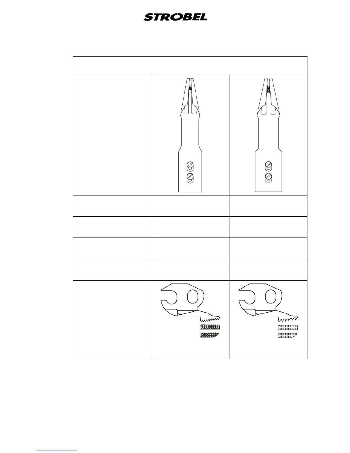
38 BA_VEB100-7_A4_180618_en
Cl. VEB100-7
Hemmer
Thin fabric
386.0441
Standard
386.0444
Optional part
Medium fabric
386.0442
Standard
386.0445
Optional part
Thick fabric
386.0443
Optional part
386.0446
Optional part
Hemmer size
9.5 mm
3/8″
11 mm
7/16″
Feed dog
182.0299
Standard
182.0300
Optional part
Page 43
39 BA_VEB100-7_A4_180618_en
8
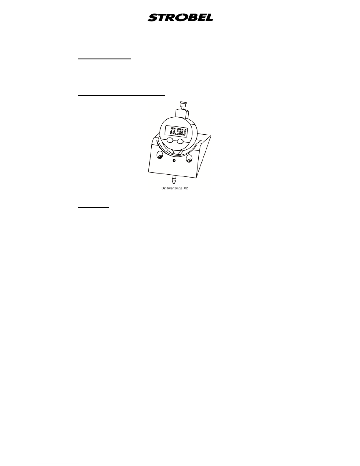
The following devices are available as optional extras and can be ordered
together with the machine or as separate kits.
Optional parts
8.1 Digital display 392.0637
8.2
More hemmer sizes on request.
Hemmer
Page 44

Page 45
Und wir können noch mehr für Sie tun!
And we can do a lot more for you!
Unser Lieferprogramm bietet für jede Branche und
jegliche Anforderung genau die richtige Problemlösung.
Our range offers the correct problem solution for
every branch and for all requirements.
Für die Bekleidungsindustrie:
Für die Schuhverarbeitung:
Für die Polsterverarbeitung:
Ein- und ZweifadenHochleistungs-Saummaschinen
DoppelblindstichSaummaschinen
Zweifaden-BlindstichStafermaschinen
Roll- und Flachpikiermaschinen
Pikier-Automat
und
weitere Spezial-Nähmaschinen
Einfaden-Überwendlichmaschinen mit und ohne
Differentialtransport
Ein- und ZweifadenÜberwendlichmaschinen
Ein- und ZweifadenBlindstichmaschinen
For the clothing
industry:
Single and two thread high
performance hemming
machines
Bluff edge hemming machines
Two thread blind stitch felling
machines
Roll and at padding machines
Automatic lapel padding
machine
and other special sewing
machines
For the shoe industry:
Single-thread overseaming machines with and without differential feed
Für Kürschnereien
und Pelzkonfektion:
Pelzschnellnäher
For the fur industry:
High-speed fur sewing machines
Für Heimtextilien:
Ein- und ZweifadenBlindstichmaschinen
For the home textiles
industry:
Single and two thread
blind stitch machines
For the upholstery
industry:
Single and two thread
overseaming machines
Single and two thread
blind stitch machines
Für die Konfektion
technischer Textilien:
Ein- und ZweifadenÜberwendlichmaschinen
For the processing
of technical textiles:
Single and two thread
overseaming machines
Page 46

Noch Fragen?
Any further questions?
Dann rufen Sie uns an, schreiben Sie uns oder
kommen Sie einfach bei uns vorbei.
Sie können jederzeit weitere Informationen über
unsere Produkte anfodern oder die StrobelNähmaschinen in unserem Ausstellungsraum live
erleben. Wir freuen uns auf Sie!
Then phone, write or simply come and see us. You
can have further information about our products at
any time, or experience the Strobel machines live in
our show room. We’re looking forward to meeting you!
Sp ez ia l m a sc hi ne n G mb H
Postfach 1242
82168 Puchheim
Siemensstraße 3
82178 Puchheim
DEUTSCHLAND
www.strobel.biz
Telefon: +49 89 80096-0
Telefax: +49 89 80096-190
 Loading...