


For the professional user
Mechanic‘s Instructions
Für den professionellen Anwender
Mechanikeranleitung
Class:
Klasse:
Model:
Ausführung:
Dated:
Stand:
VEB100-3
2
Spezialmaschinen GmbH

The sign of quality
ou nd the Strobel trademark on every Strobel
Y
machine leaving our works. And with good reason.
This symbol is a guarantee of the high quality of
our products. Quality which creates trust – trust
in our technology, our service and, not least of all,
in our good name.
Im Zeichen der Qualität
ie nden die Strobel-Schutzmarke auf jeder
S
Strobel-Maschine, die unser Werk verlässt.
Und das aus gutem Grund. Denn dieses Zeichen
garantiert Ihnen die hohe Qualität unserer
Produkte. Qualität, die Vertrauen schafft – in unsere
Technik, unseren Service und nicht zuletzt in unseren
guten Namen.

A decision with future
trobel clients know that they can expect a particularly
S
high standard of performance from our company and our
machines. Now you have settled for one of our products.
For us this is a source of encouragement and of obligation
to Justify your trust.
If you wish to prot from the performance and efciency of
your Strobel machine as long as possible, exact handling
and thorough care is necessary. For this reason we kindly
request that you read the operating instructions closely.
It provides all the information you need for trouble free
operation.
And if you do happen to need a spare part the enclosed
spare parts list gives a complete overview. It is clearly
classied according to components so that you can nd the
required part quickly and easily. In order to avoid errors we
request you to quote machine class, machine number and
part number completely on your spare part order.
We wish you lots of success in your work with your new
Strobel machine.
Spezialmaschinen GmbH


Mechanic’s instructions
STROBEL Class VEB100-3
Table of contents
1 General notes on safety ............................................................................................ 5
2 General notes ............................................................................................................ 7
2.1 Operating instructions ..................................................................................... 7
2.2 Class designations, machine number and initial basis for descriptions .......... 7
2.3 Applications of the machine ............................................................................ 7
2.4 Technical data of machine .............................................................................. 8
2.5 Abridged version of adjustment manual .......................................................... 9
3 Notes on repair and adjustments ............................................................................. 10
3.1 Needle plate assembly.................................................................................. 10
3.1.1 Removing the needle plate (Fig. 1) .................................................. 10
3.1.2 Installing the needle plate (Fig. 1) .................................................... 12
3.1.3 Adjusting the needle plate (Fig. 2) .................................................... 12
3.1.4 Replacing the needle slide plate (Fig. 3) .......................................... 12
3.1.5 Adjusting the cloth retainer (Fig. 4) .................................................. 13
3.2 Needle lever .................................................................................................. 14
3.2.1 Assembly .......................................................................................... 14
3.2.2 Adjusting the needle stroke (Fig. 6, Fig. 7 and Fig. 9) ...................... 15
3.3 Loop stroke ................................................................................................... 17
3.3.1 Adjusting the loop stroke .................................................................. 17
3.4 Looper ........................................................................................................... 18
3.4.1 Removal and installation of the looper shaft..................................... 18
3.4.2 Looper deflection (Fig. 8) ................................................................. 18
3.4.3 Adjusting the looper (Fig. 9) ............................................................. 19
3.5 Feed dogs ..................................................................................................... 20
3.5.1 Adjusting the feed dog (Fig. 10) ....................................................... 20
3.5.2 Adjusting the bottom bel t feed .......................................................... 21
3.5.2.1 Belt tension ..................................................................... 21
3.5.2.2 Presser plate pressure (Fig. 11) ...................................... 21
3.5.2.3 Belt feed lifting (Fig. 11) .................................................. 21
3.5.2.4 Belt exchange (Fig. 12) ................................................... 22
3.6 Plunger ......................................................................................................... 23
3.6.1 Plunger exchange (Fig. 13) .............................................................. 23
3.6.2 Plunger adjustment (Fig. 13) ............................................................ 23
3.6.3 Adjusting the material support arm ................................................... 24
3.6.4 Setting the pre-tension of the spring in spring-loaded plungers ....... 24
1 MA_VEB100-3_A2_181015_en

3.7 Pneumatic lifting ........................................................................................... 25
3.7.1 Setting the lifting ............................................................................... 25
3.8 Thread trimmer (Fig. 15) ............................................................................... 26
3.8.1 Removing and remounting of the thread trimmer drive (Fig. 15) ...... 27
3.8.2 Adjustment ....................................................................................... 27
3.8.3 Replacing the knife (Fig. 15 und Fig. 16) ......................................... 28
3.8.4 Cutting position (Fig. 16) .................................................................. 28
3.9 Motor............................................................................................................. 28
3.10 Motor............................................................................................................. 28
3.11 Seam Lock .................................................................................................... 29
2 MA_VEB100-3_A2_181015_en

Appendix
Circuit diagrams
Electric mains, sewing drive - sewing machine lamp:
258.00.35 Mains connection plan cl. general
(AB611A with/without sewing machine lamp gen.)
Connecting the sewing machine:
258.21.63 Electrical connection plan cl. 45, 58, 103, 120, 170, VEB
258.21.75 Electrical connection plan cl. VEB with seam lock
259.00.37 Pneumatic circuit diagram cl. gen. with pneum. lifting
259.10.37 Pneumatic construction circuit diagram cl. gen.
with pneum. Lifting
259.00.66 Pneumatic circuit diagram cl. VEB100-3 with seam lock
259.10.66 Pneumatic construction circuit diagram cl. VEB100-3
with seam lock
Connecting Thread trimmer:
258.21.47 Electrical connection diagram cl. gen. – thread trimmer
We reserve the right to make design changes.
3 MA_VEB100-3_A2_181015_en

4 MA_VEB100-3_A2_181015_en

1
General notes on safety
Every person in charge of setting up, operating, servicing and repairing the
machine must first read and understand the operating instructions and
particularly the safety instructions before starting up the machine.
Failure to comply with the following safety instructions can lead to bodily
injury or damage to the machine.
1. The machine must only be operated by persons familiar with the relevant
operating instructions and who have been instructed accordingly.
2. Before commissioning also read the notes on safety and the operating
instructions of the sewing drive manufacturer.
3. Only use the machine in the intended manner and never without the
provided guards. Always observe the pertinent safety regulations.
4. Switch off the main switch or pull the power plug for threading, changing
the reels, exchanging sewing tools such as needle, gripper, needle plate,
transport devices, possibly cutter and cutting block, for cleaning and when
leaving the workplace as well as for maintenance.
5. General maintenance tasks may be carried out only by properly trained
persons in accordance with the operating instructions.
6. Repair work, retrofitting and maintenance may be carried out only by
technicians or specially trained personnel.
7. When servicing or repairing pneumatic equipment, the machine must be
disconnected from the pneumatic supply. Exceptions are only allowed for
adjustment work and tests of functionality performed by specially trained
technicians.
8. Only specially qualified technicians may work on the electrical equipment.
9. It is forbidden to work on electrically live components! Exemptions are
covered by the EN50110 (DIN VDE0105) regulations.
10. Any retrofitting or alterations to the machine may only be performed under
strict compliance with all pertinent safety regulations.
11. Only use our approved spare parts when servicing and/or repairing the
machine.
12. It is forbidden to operate the sewing head until it is determined that the
entire sewing unit complies with EU provisions.
13. It is essential that you observe and follow these instructions as well as the
generally valid safety regulations.
5 MA_VEB100-3_A2_181015_en

14. Warning instructions given in the operating instructions that pertain to
especially dangerous parts of the machine must be indicated at these
positions using a safety symbol.
Warning instructions given in the operating instructions that pertain to
special injury hazards for operating personnel or technicians must be
indicated at these positions using a safety symbol.
6 MA_VEB100-3_A2_181015_en

2
2.1
2.2
2.3
General notes
Operating instructions
Every person in charge of setting up, operating, servicing and repairing the
machine must first read and understand the operating instructions and
particularly the safety instructions before starting up the machine.
Class designations, machine number and initial basis for descriptions
The operating side of the machine is the initial basis for left/right descriptions.
The class designation (type) and machine/model numbers are fastened to the
rear of the machine case.
This data is also noted on the front cover page of the operating instructions.
Applications of the machine
Class VEB100-3 is suitable for attaching waistbands linings on trousers, also for
waistbands with belt loops attached.
The range of applications of the different machines can be extended by
exchanging the variable sewing tools, i.e. those other fabric qualities than the
ones mentioned above can be sewn as well.
Variable sewing tools please see point 7 in operating instruction.
7 MA_VEB100-3_A2_181015_en

2.4
Technical data of machine
Recommended rated speed: 2200 min-1
Machine pulley diamet er dw 80 mm
Min. motor power 550 W
V-belt profile 10 x 6 mm
Toothed belt pulley/ma c hine Z=38
Toothed belt profile HTD 5M-9
Stitch length-upper feed 5 - 8 mm
(depend on fabric)
Kind of stitch: single thread chain stitch blind stitch
Stitch type 103
Needle system GROZ-BECKERT 1669 EEO
Needle size 90
Thread polyester continuous filament
Thread size 120/2
Pneumatic connection 6 bar
Average air consumption depending on the equipement
Required space 0.5 m x 1.1 m
Noise:
Average noise level at a speed of
n = 2200 min-1: LpAm 71 dB (A)
Noise test according to DIN 45635-48-1 KL3
8 MA_VEB100-3_A2_181015_en

2.5
Abridged version of adjustme nt manual
Theoretic needle radiu s : 41.3 mm
Left needle guide: 41.33 +0.02 mm
Needle glide plate: 41.30 ±0.01 mm
Right needle guide: 41.40 +0.05 m m
Needle stroke, needle ey e to looper fing er : 1.5 +0.5 mm
Ball pin to needle shaft: 4 ±0.5 mm
Slot ball pin: approx. 15°
Looper stroke: 18 +0.5 mm
Pressures:
Feed plate: left 12 N
right 12 N
Cloth support arm: 140 N (meas. at presser shaft)
Plunger limit stop: 6 N
Feed length: approx. 5 - 8 mm
Lifting between needle plate
and feed plates: approx. 13 mm
Lifting between needle
and plunger: approx. 10 mm
Loop stroke: 2.8 +0.3 mm
Number of spot tacks 2 – 4 stitches
9 MA_VEB100-3_A2_181015_en

Read the safety and operating instructions before
Switch off the machine electrically!
3
3.1
Notes on repair and adjustments
CAUTION! Injury hazard!
performing maintenance and/or repair work. Failure to
comply with them can lead to severe bodily injury.
Needle plate assembly
CAUTION! Injury hazard!
Needle plates are adjusted at the factory and can be easily exchanged in their
entirety. When replacing needle guide(s), the adjusting dimensions must be
rechecked using a dial gauge. After removing the needle lever, the dial gauge is
inserted into the needle shaft and, by turning the handwheel, touches the
surface of the needle guide.
3.1.1
Removing the needle pl ate (Fig. 1)
1. Switch off machine electrically, cloth support arm is lifted.
2. Remove needle and needle lever.
3. Remove the thread trimmer's drive unit as described under “3.8.1
Removing and remounting of the thread trimmer drive (Fig. 15)” or pu ll the
plug only.
4. Release needle plate fas tening screws (1) and (2) and remove the
complete needle plate uni t to th e fro nt.
10 MA_VEB100-3_A2_181015_en

Fig. 1
11 MA_VEB100-3_A2_181015_en

3.1.2
3.1.3
Install ing the needle plate (Fig. 1)
Remount the needle plate in reversed order but make sure that the needle plate
opening is mounted centrically to the presser foot and that the needle plate is
mounted horizontally. Push the needle plate bow completely upwards until
threaded pin (3) fits closely to the needle shaft bush.
Adjusting the needle plate (Fig. 2)
At the left needle guide, the theoretical needle radius of 41.3 mm should be
0.03 to 0.05 mm larger. At the needle slide plate, it should be 0.01 mm smaller
to 0.01 mm larger and at the right needle guide it should be 0.06 to 0.08 mm
larger.
The adjustment must be made using a dial gauge. Deviations lead to
significantly poorer sewing results and may even cause preliminary damage or
wear to the sewing tools.
Fig. 2
3.1.4
Replacing the needle sl ide plate (Fig. 3)
The needle slide plate on the central base of the needle plate can be removed
after loosening the screw (1).
When assembling, ensure that the needle slide plate lies firmly against the base.
12 MA_VEB100-3_A2_181015_en

Fig. 3
3.1.5
Adjusting the cloth retainer (Fig. 4)
After replacing the needle plate, check whether the cloth retainer
centrally on the plunger. This is particularly important for roof-shaped
plungers/cloth retainers to ensure that the material is optimally held during
sewing.
(2) Fig. 3 lies
Fig. 4
13 MA_VEB100-3_A2_181015_en

Switch off the machine electrically!
3.2
3.2.1
Needle lever
Assembly
CAUTION!
Remove screw (10) Fig. 6, move the Thread take-up lever and remove the
needle lever. During installation, please ensure that the needle runs through the
centre of the needle groove and the needle tip is flush with the left needle guide
(Fig. 5).
Fig. 5
14 MA_VEB100-3_A2_181015_en

3.2.2
Adjusting the needle stroke (Fig. 6, Fig. 7 and Fig. 9)
For a loop stroke of 2.3–3.0 mm, the needle stroke must be set to that the left
side of the needle’s eye is approx. 1.0 +0.5 mm away from the large gripping
finger when the tip of the large gripping finger is above the centre of the needle
(
Fig. 9).
The head cover must be removed for the adjustment. After removing (hex key
size 4) screw (1) shown in Fig. 7, the ball pin (2) shown in Fig. 6 can be
adjusted using a slotted screwdriver.
In the horizontal position, insert the ball pin so that the slot of the ø6 bolt stands
vertically beneath the ø7 bolt.
Rotating it clockwise will result in a larger needle stroke while turning it in the
opposite direction will create a smaller needle stroke.
The distance between the ball pin and needle shaft is 2 ±0.5 mm. After
adjusting the needle stroke, the needle lever must be configured as described in
section “3.2.1 Assembly”.
Tighten the screw (1) shown in Fig. 7.
Check the looper and needle mov eme nt by turning the main shaft using the
handwheel.
Fig. 6
15 MA_VEB100-3_A2_181015_en

Fig. 7
16 MA_VEB100-3_A2_181015_en

Switch off the machine electrically!
3.3
3.3.1
Loop stroke
The loop stroke is the path of the needle from its right reversal point to the point
where the tip of the large gripping finger stands above the centre of the needle.
(
Fig. 9)
Adjusting the loop stroke
CAUTION!
In the factory setting, the loop stroke is 2.3–3.0 mm. (Fig. 9)
Adjustment:
- Unscrew the head of the connecting rod: Loop stroke becomes smaller
- Screw in the head of the connecting rod: Loop stroke becomes larger
Thread slope = 0.5 mm per rotation
The following steps are requi r ed to rotate the head of the connecting rod (Fig. 6
and Fig. 7):
1. Unscrew the fillister head screw (9) Fig. 6 and push the looper forwards.
2. Remove the nut (5) Fig. 6 from the looper shaft.
3. Remove the cylinder head screws (4) Fig. 6 from the head of the
connecting rod (3) Fig. 6.
4. Remove the adjusting ring (3) Fig. 7 and pull out the looper shaft including
the head of the connecting rod (3) Fig. 6 from the cross-beds (5) Fig. 7.
Do not remove the contoured bolt (4) Fig. 7!
The loop stroke can be determined using a special dial gauge or vernier caliper.
17 MA_VEB100-3_A2_181015_en

Switch off the machine electrically!
3.4
3.4.1
3.4.2
Looper
Removing and installing the looper
(Fig. 6)
CAUTION!
After removing the fillister head screw (9), the looper can be remov ed from the
front.
When installing, ensure that the fastening surface of the looper lies within the
chuck and is fully inserted. Tighten the fillister screw (9).
Removal and installation of the looper shaft
After removing the looper and loosening the adjusting rings
(3) Fig. 7, the looper shaft can be removed together with the ball joint lever (7)
Fig. 6.
(8) Fig. 6 and
Looper deflection (Fig. 8)
The looper deflection is 18 +0.5 (specification).
Fig. 8
18 MA_VEB100-3_A2_181015_en

3.4.3
Adjusting the looper (Fig. 9)
At the moment when the loop is picked up, the gripping finger must lie
0.1–0.2 mm above the needle. This must also be observed when changing
the needle thickness. It is essential to prevent needle contact from occurring!
The horizontal distance from the large gripping finger to the eye of the needle
should be 1.5 +0.5 mm (Fig. 9). On the left side where the loop is released, the
needle must pass centrally in between the two gripping fingers. These values
can be adjusted by turning and moving the adjusting cam (6) Fig. 7 and rotating
the looper shaft against the head of the connecting rod (3) Fig. 6.
Check the looper movement by carefully turning the main shaft using the
handwheel!
Check that all fastening screws are firmly installed!
Fig. 9
19 MA_VEB100-3_A2_181015_en

Switch off the machine electrically!
3.5
3.5.1
Feed dogs
The machine is equipped ex works with the pyramid-toothed feed dog. After
loosening the two screws, its motion towards the needle plate can be adjusted.
Adjusting the feed dog (Fig. 10)
CAUTION!
1. Set the stitch length to 8 mm.
2. Clamp down the feed dog so that it lies parallel to the needle plate and
the lower part of the tooth protrudes beneath the bottom of the needl e
plate. It must not collide with the sides of the needle plate opening amd
should be set forwards as far as possible towards the needle.
Clamp a piece of paper with 0.2 mm to the tip of the needle 2 mm in front of the
centre of the plunger.
Fig. 10
20 MA_VEB100-3_A2_181015_en

3.5.2
3.5.2.1
3.5.2.2
Adjusting the bottom belt feed
Belt tension
Please see point „4.8.3 Tighten feeding belts“ in operating instructions.
Presser plate pressure (Fig. 11)
The right plate could be adjusted with screw (1) at the arm.
Turning clockwise – more pressure
Turning anti-clockwise – less pressure.
The left plate could be adjusted with screw (2) at the arm extension.
Same rule as above.
Fig. 11
3.5.2.3
Belt feed lifting (Fig. 11)
The presser plates get lifted together with the arm. The left plate by the
adjustable eccentri c bolt (3) at the arm extens i on (4) and the right plate by the
screw (5) at the lever (6).
Both adjustments are made fro m t he bottom of the arm.
At highest position of the arm must be 1-2mm distance between lever and
bolt/screw. Otherwise the belts have no contact to the stitch plate, if the plunger
is adjusted for heavy fabric.
21 MA_VEB100-3_A2_181015_en
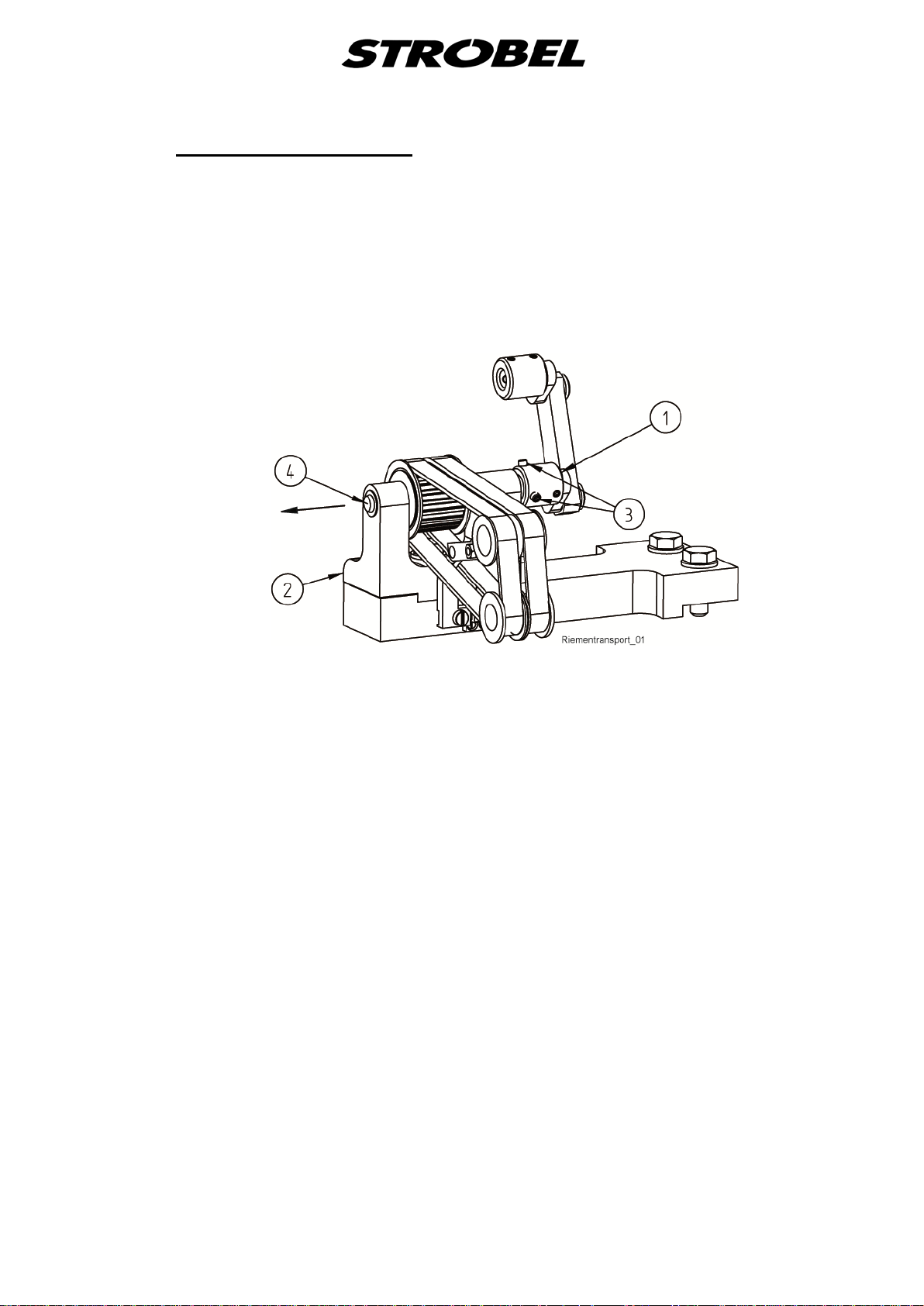
3.5.2.4
Belt exchange (Fig. 12)
Open the bo th left screws (3) from the lower collar (1) at the bench (2) and pull
out the shaft (4) to the left side. Push down the arm manually and take out the
belts and the belt gears to the left side.
Assembly in the reverse sequence.
Attention: Take care about the sense of rotation of the gear belts. The belts
must move backwards.
Fig. 12
22 MA_VEB100-3_A2_181015_en
3.6
3.6.1
3.6.2
Plunger
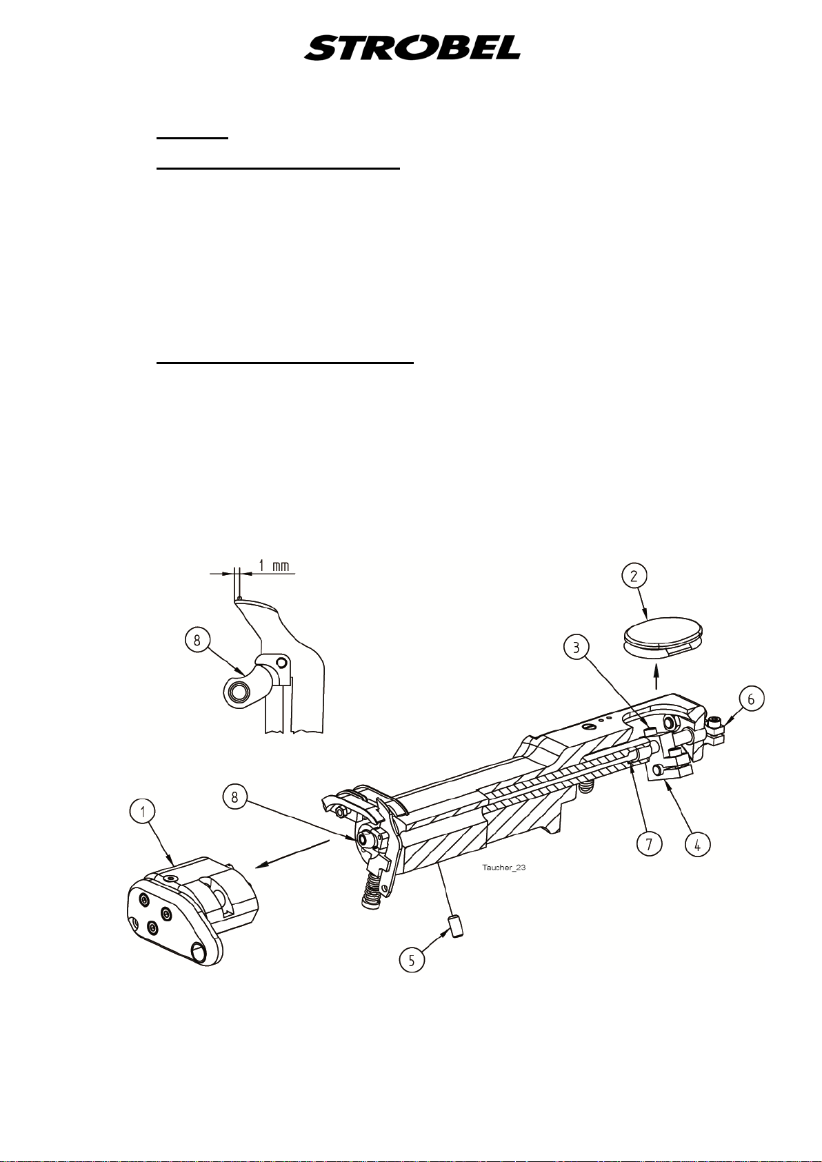
Plunger e xchange (Fig. 13)
1. Remove the arm extension (1).
2. Remove the cover (2).
3. Loose screw (3) at lever (4).
4. Loose screw (5) at the bottom o f the arm.
5. Loose set collar (6) and remove the complete plunger.
Assembly in the reverse sequence.
Plunger adjust men t (Fig. 13)
1. Adjust the plunger centre to the centre of the cloth retainer, plunger fr ont
1 mm behind the needle and fix with screw (5) this position.
2. Adjust the plunger shaft (7) without clearance with the collar (6).
3. Turn the hand wheel till the needle top point is in the centre of the plunger.
4. Turn the plunger shaft (7) till the cam (8) is in the position as shown in Fig.
13 and tight the screw (3) at lever (4).
Fig. 13
23 MA_VEB100-3_A2_181015_en

3.6.3
Adjusting the material support arm
Turn the main shaft until the needle tip stands 1–2 mm behind the centre of the
plunger.
Adjust the control knob Fig. 14 so that the needle is lifted by 0.2 mm, then
screw in the threaded pin (5) Fig. 14 until it lies against the case. Next, counter
the threaded pin (6) Fig. 14.
The material support arm must be adjusted to have no axial backlash.
Fig. 14
3.6.4
24 MA_VEB100-3_A2_181015_en
Setting t he pre-tension of the sprin g in spring-loaded plungers
The spring-loaded plunger is hold under tension by means of a tension spring in
the plunger lever. For adjustments use the screw drive supplied with the
machine.

Switch off the machine electrically!
3.7
3.7.1
Pneumatic lifting
CAUTION!
Setting the lifting
Reduce the lifting speed of the cloth support arm at the one-way restrictor so
that there is no hard noise when the arm is lowered.
The piston in the pneumatic cylinder should move up to the limit stop. When the
cloth support arm is lowered it should be possible to press it down by
approx. 1 mm.
25 MA_VEB100-3_A2_181015_en
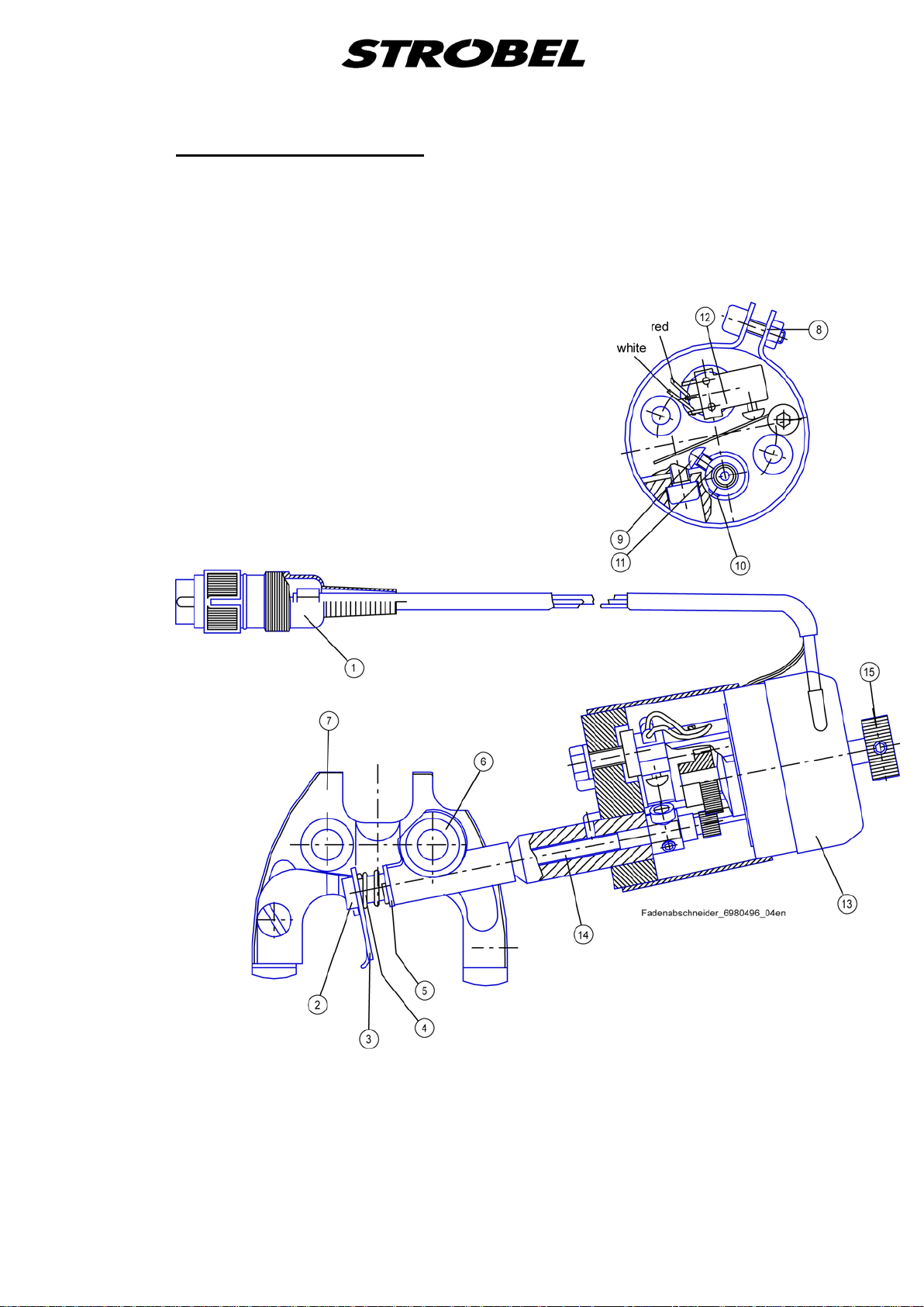
3.8
Thread trimmer (Fig. 15)
The blade of the thread trimmer is activated by a rotary magnet, to which an
electric release control system (microswitch) is connected. This prevents the
machine from starting when the blade is no longer in its inital position. Thus the
release control system prevents a possible collision between blade and looper.
Fig. 15
26 MA_VEB100-3_A2_181015_en

Switch off the machine electrically!
3.8.1
3.8.2
Removing and remounting of the thread trimmer drive (Fig. 15)
CAUTION!
1. Remove plug (1).
2. Loosen the screw (2) and remove from blade (3), spring (4) and disc (5).
3. Loosen the screw (6) on the needle plate clamp (7) and remove the thread
trimmer drive.
4. Installation in reverse order.
Ensure the blade is in correct position on the shaft!
Adjustment
- The thread trimmer drive must be inserted as far as it will go into the
needle plate clamp.
Swivel the drive backwards so that there is a gap of about 1 mm between
the drive and the sewing head.
- The blade of the knife has until about 2 - 3 mm from needle lever, stand
forward, readjust if necessary.
Remove clamp (8).
Loosen the screws (9) and (10) on the small gearwheel (11) and adjust by
turning the blade shaft.
Push together gearwheel and blade shaft to the limit and tighten.
- Setting the microswitch (12) and gearwheel (11).
- When replacing the rotary magnet (13), ensure that the toot h gap be t ween
the gearwheels is approx. 0.1 mm.
Ensure free movement of parts!
27 MA_VEB100-3_A2_181015_en
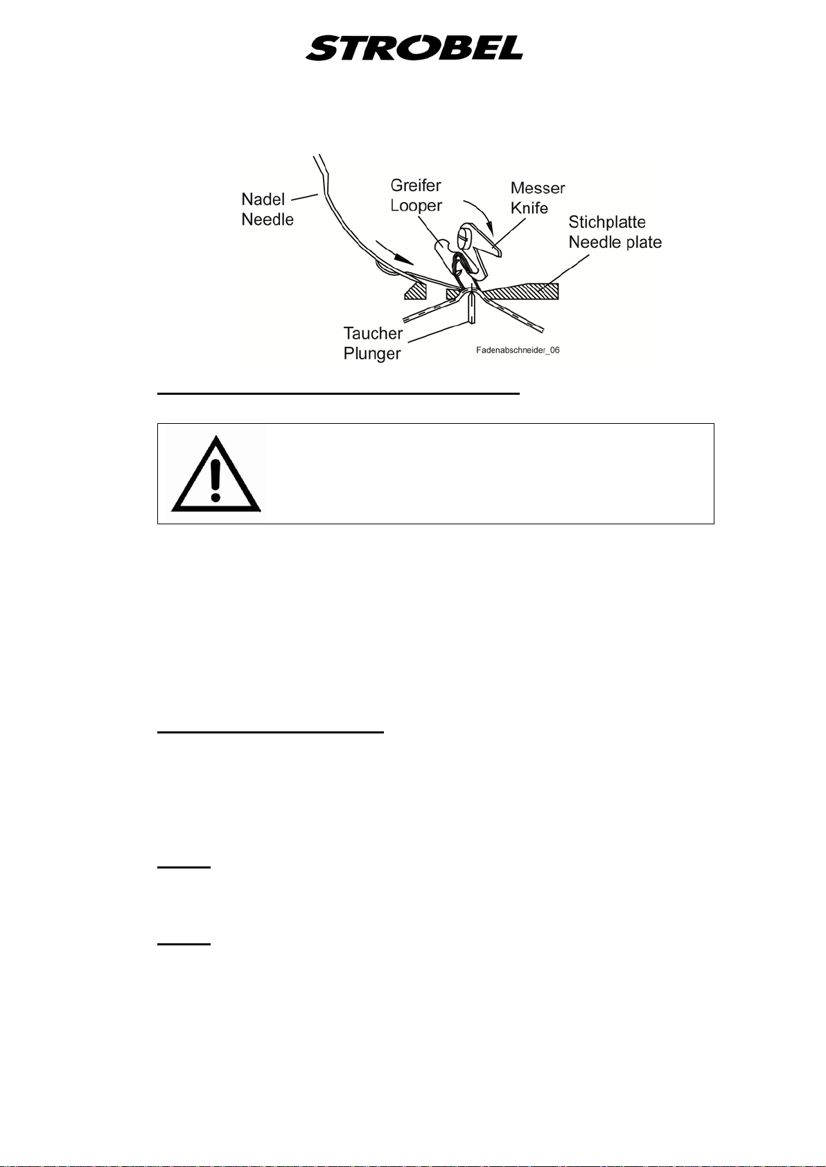
Fig. 16
Switch off the machine electrically!
3.8.3
3.8.4
Replacing the knife (Fig. 15 und Fig. 16)
CAUTION!
To replace cylinder head screw (2), unscrew it (hold shaft (14) with open-end
wrench 5 mm).
Caution: Do not hold onto the rotary knob (15) since the gearwheels can be
damaged!
The nose of knife (3) should sit in the shaft's groove to guarantee the right
position for the thread trimming.
Turn the main shaft manually and check the trimming position. (Fig. 16)
Cutting position (Fig. 16)
The machine should be positioned in such a way as the pedal is stepped back
that the distance between looper and blade in cutting position is approx. 1 mm.
For Strobel and EFKA controls, this corresponds to parameter 171, position
P2E.
Refer also to the sewing drive operating instructions.
3.9
3.10
28 MA_VEB100-3_A2_181015_en
Motor
Separate operating instructions with programming instructions and wiring
diagrams are supplied with the motor.
Motor
Separate operating instructions with programming instructions and wiring
diagrams are supplied with the motor.

3.11
Seam Lock
Locking the seam is made by a stitch without catching the fabric.
The plunger drops down and a second thread tension is activated.
By additional lowering the cloth support arm the seam lock is made.
The thread get hold by second thread tension and a skip stitch make the seam
lock.
The lifting of cloth support arm can be adjusted by the hand wheel underneath
the table.
Feed dog will be not lifted during seam lock.
29 MA_VEB100-3_A2_181015_en

Nähleuchte (allg.)
sewing light (gen.)
Netzanschluss
power connection
258.00.35
Netz-Anschlussplan Kl. allg.
(AB611A mit/ohne Nähleuchte allg.)
Mains connection plan cl. gen.
(AB611A with/without sewing light gen.)
Kabelbefestigung mit Kabelbinder
cable mounting with cable strap
3x 293.0290
Kabelzugentlastung
cable strain relief
193.0992
Rechtes Gehäuseteil
right casing
Linkes Gehäuseteil
left casing
Steuerkasten
control box
Efka-AB611A
Sicherung (8,0A M)
fuse (8,0A M)
293.0978
195.0042
gn-ge / gn-ye
bl / bu
br / bn
bl / bu
br / bn
bl / bu
br / bn
F 8,0A M
F 8,0A M

ST2
+5V / 0,2A
0V
+15V / 0,3A
+24V(1)
+24V(1)
+24V(1)
0V
POS1Q
POS2Q
G1Q
3A
+24V(1)
+24V(1)
3A
0,5A
0,5A
0,5A
6,5A
6,5A
3A
3A
0,5A
0,5A
0,5A
0,5A
LÜ ( MV1 )
FA
LSP
258.21.63en
Electrical connection plan cl. 45, 58, 103, 120, 170, VEB
(DC1200-AB611A)
Control box Efka drive
(1) Nominal voltage 24V, idle voltage max. 30V
Designation
Strobel operating manual
Thread trimmer (FA) Output 1 (M1) 37
Run inhibition (LSP) Input 1 (IN1) 7
Lifting (LÜ) Press foot lifting (FL) 35
Designation
Efka operating manual
PIN
37 pin
Sub-D
16
4
17
Colour code
connection cable
yellow
brown
grey
blue
white
brown

ST2
+5V / 0,2A
0V
+15V / 0,3A
+24V(1)
+24V(1)
+24V(1)
0V
POS1Q
POS2Q
G1Q
3A
+24V(1)
+24V(1)
3A
0,5A
0,5A
0,5A
6,5A
6,5A
3A
3A
0,5A
0,5A
0,5A
0,5A
LÜ ( MV1 )
FA
LSP
VR ( MV2 )
258.21.75en
Electrical connection plan cl. VEB with seam lock
(DC12xx-AB611A)
Control box Efka drive
(1) Nominal voltage 24V, idle voltage max. 30V
Designation
Strobel operating manual
Thread trimmer (FA) Output 1 (M1) 37
Run inhibition (LSP) Input 1 (IN1 7
Lifting (LÜ) Press foot lifting (FL) 35
Locking system (VR) Locking system (VR) 34
Designation
Efka operating manual
PIN
37 pin
Sub-D
16
4
17
17
Colour code
connection cable
yellow
brown
grey
blue
white
brown
green
brown

259.00.37
Pneumatischer Schaltplan Kl. allg. mit pneum. Lüftung
(Efka-DC1200/DC1210)
Pneumatic circuit diagram cl. gen. with pneum. lifting
(Efka DC1200/DC1210)
1A1
10bar max
0 Z 1
1V1
1V10
6bar
A
P
R
195.0513
0 Z 1 Wartungseinheit Service unit
1 V 1 3/2-Magnetventil "Lüftung" 3/2-solenoid-way valve "lifting"
1 V 10 Drosselrückschlagventil "Lüftung" throttle non-return valve "lifting"
1 A 1 Zylinder "Lüftung" cylinder "lifting"
259.10.37
Pneumatischer Bauschaltplan Kl. allg. mit pneum. Lüftung
(Efka-DC1200/DC1210)
Pneumatic construction circuit diagram cl. gen. with pneum. lifting
(Efka-DC1200/DC1210)
Wartungseinheit
service unit
293.0975
(293.0841)
297.0170
Lüftung
lifting
(293.0850)
Magnetventil
solenoid valve
293.0469
8
O
193.0478 3000 lg
6
O
193.0473 500 lg
R
1 V 1
P (R)
193.0658
193.0530
298.0179
293.0852
A
293.0850
193.0473 450 lg
O
6
298.0077
293.0470
293.0850
A
Kl. allg. 298.0546
B
Cl. gen.
Kl. 170 298.0680
293.0469
Cl. 170
195.0514
233.0713 2 Reduziernippel R1/4-R1/8 (nur Kl. 170) reduction nipple R1/4-R1/8 (only Cl. 170)
293.0469 2 Schalldämpfer R1/8 silencer R1/8
293.0470 1 Doppelnippel R1/8 nipple R1/8
193.0473 950 PA-Schlauch Ø6 PA hose Ø6
193.0478 3000 PA-Schlauch Ø8 PA hose Ø8
193.0530 1 Dichtungsring R1/8 gasket R1/8
193.0658 1 Muffe R1/8 bushing R1/8
293.0850 2 L-Einschraubanschluss R1/8-6 L-threaded connection R1/8-6
293.0852 1 G-Einschraubanschluss R1/8-6 threaded connection R1/8-6
293.0975 1 Wartungseinheit service unit
297.0170 1 Schnellverschlusskupplung Ø8 coupling Ø8
298.0077 1 Drosselrückschlagventil R1/8 throttle non-return valve R1/8
298.0179 1 3/2 Wege-Magnetventil 3/2-solenoid-way valve
298.0546 1 Kurzhubzylinder Ø32x25 (Kl. allg.) short stroke cylinder Ø32x25 (Cl. gen.)
298.0680 1 Kurzhubzylinder Ø50x25 (Kl. 170) short stroke cylinder Ø50x25 (Cl. 170)
2x 233.0713 (nur Kl. 170 / only Cl. 170)

259.00.66
Pneumatischer Schaltplan Kl. VEB100-3 mit Nahtsicherung
(Efka-DC1200)
Pneumatic circuit diagram cl. VEB100-3 with seam lock
(Efka-DC1200)
10bar max
1V10
0 Z 1
1V1
1A1
6bar
B
P R
1A2
A
1V2
B
A
P R
195.0517
0 Z 1 Wartungseinheit Service unit
1 V 1 4/2-Magnetventil "Lüftung" 4/2-solenoid-way valve "lifting"
1 V 2 4/2-Magnetventil "Zwischenlüftung" 4/2-solenoid-way valve "intermediate lifting"
1 V 10 Drosselrückschlagventil "Lüftung" One-way flow restrictor "lifting"
1 A 1 Zylinder "Lüftung" Cylinder "lifting"
1 A 2 Zylinder "Zwischenlüftung" Cylinder "intermediate lifting"

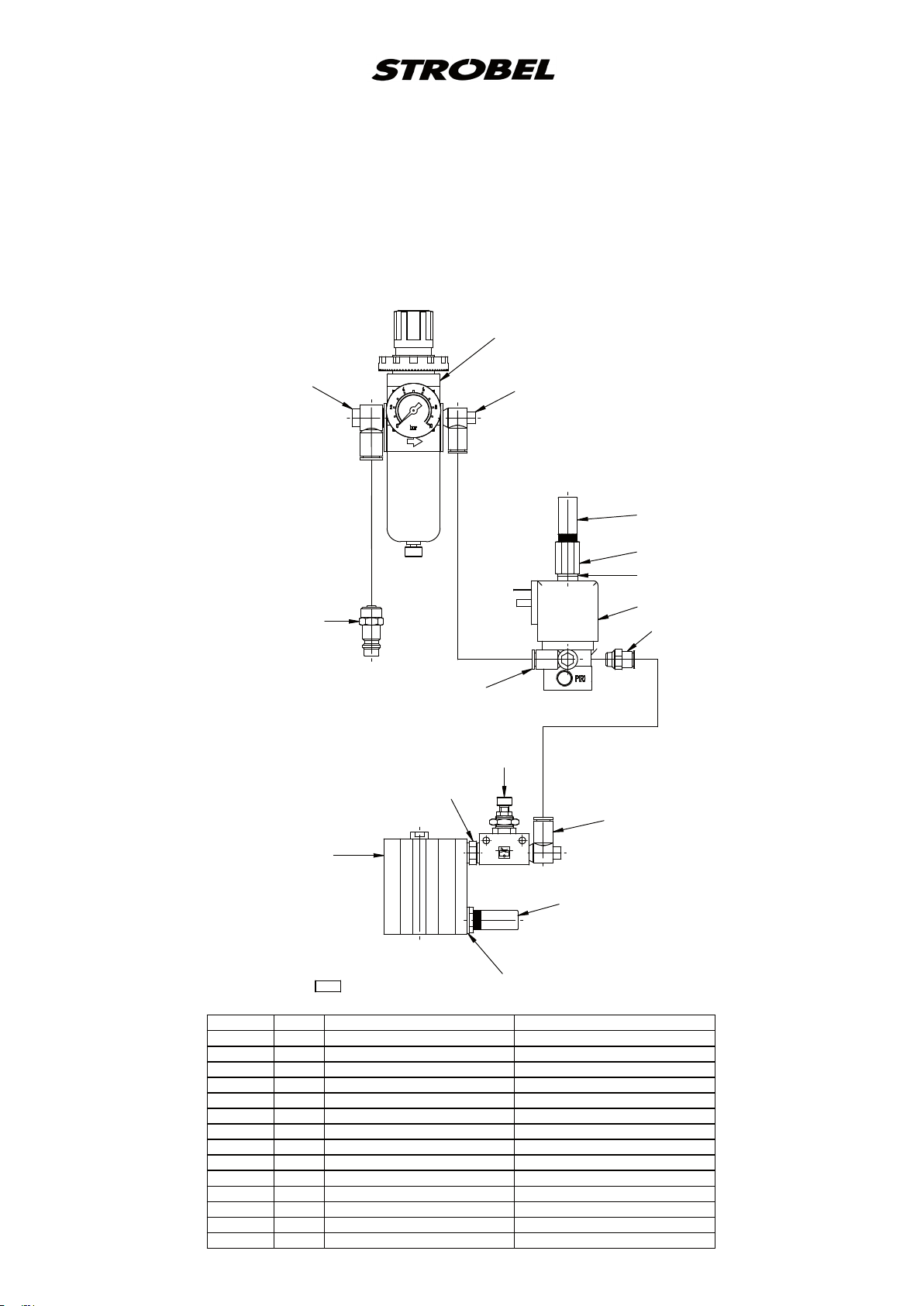
259.10.66
Pneumatischer Bauschaltplan Kl. VEB100-3 mit Nahtsicherung
(Efka-DC1200)
Pneumatic construction circuit diagram cl. VEB100-3 with seam lock
(Efka-DC1200)
Magnetventil
Wartungseinheit
2x 298.0510
solenoid valve
Beschriften
service unit
298.0512
L2
L1
L2
L1
293.0975
4x 293.0850
1V2
1V1
3x 293.0772
298.0511
(293.0850)
r
3
1V2
1V1
r
3
293.0469
293.0469 2 Schalldämpfer R 1/8 silencer R 1/8
293.0470 1 Doppelnippel R 1/8 nipple R 1/8
193.0473 2700 PA-Schlauch Ø6 PA hose Ø6
193.0478 3000 PA-Schlauch Ø8 PA hose Ø8
293.0772 3 Verschlußschraube R 1/8 lock screw R 1/8
293.0850 7 L-Einschraubanschluss R 1/8-6 L-threaded connection R 1/8-6
293.0975 1 Wartungseinheit service unit
297.0170 1 Schnellverschlusskupplung Ø8 coupling Ø8
298.0077 1 Drosselrückschlagventil R 1/8 throttle non-return valve R 1/8
298.0510 2 4/2-Wege Magnetventil 4/2-solenoid-way valve
298.0511 1 Eingangsmodul G1/8 links input module G1/8 left
298.0512 1 Eingangsmodul G1/8 rechts input module G1/8 right
298.0582 1 Kurzhubzylinder short stroke cylinder
398.0583 1 Kurzhubzylinder short stroke cylinder
O
6
2
2 B
p
1
4
4
p
1
6
O
193.0473 720 lg
3x 293.0850
O
6
193.0473 570 lg
298.0077
193.0473 680 lg
O
6
293.0470
193.0473 660 lg
A
293.0469
B
195.0518
297.0170
lifting
Lüftung
O
8
193.0478 3000 lg
298.0852
398.0853
(293.0841)

258.21.47
Elektrischer Anschlussplan Kl. allg.
Fadenabschneider
Electric connection diagram cl. gen.
Thread trimmer
Fadenabschneider
Thread trimmer
13,4
M16x 0,75
Schraubverschluß
screw coupling
Kontakt
Laufsperre
(NC)
Contact
run inhibition
(FA in Ruhestellung =
Kontakt geschlossen)
(FA at rest =
contact closed)
Rundstecker 4 pol.
Typ: Hirschmann Mas 3100 Ausf. B
circular plug 4-pin
type: Hirschmann Mas 3100 Ausf. B
Seitenansicht
side view
Verderansicht
front view
3
4
2
2
1
(C)
1
4
(NO)
rot/red
weiss/white
weiss/white
rt/rd
ws/wh
ws/wh
1 2 3 4
Drehmagnet
solenoid
Spannung/Voltage: + 24 VDC
Strom/electricity: 4 A
weiss/white
ws/wh
Spule
Spool
PIN Benennung/Description
1 NO Kontakt Laufsperre
Contact run inhibition
2 C Kontakt Laufsperre
Contact run inhibition
3 +24 V DC Spule Drehmagnet
DC Spool solenoid
4 0 V DC Spule Drehmagnet
DC Spool solenoid
195.0016


Und wir können noch mehr für Sie tun!
Unser Lieferprogramm bietet für jede Branche und
jegliche Anforderung genau die richtige Problemlösung.
And we can do a lot more for you!
Our range offers the correct problem solution for
every branch and for all requirements.
Für die Bekleidungsindustrie:
Ein- und ZweifadenHochleistungs-Saummaschinen
DoppelblindstichSaummaschinen
Zweifaden-BlindstichStafermaschinen
Roll- und Flachpikiermaschinen
Pikier-Automat
und
weitere Spezial-Nähmaschinen
For the clothing
industry:
Single and two thread high
performance hemming
machines
Bluff edge hemming machines
Two thread blind stitch felling
machines
Roll and at padding machines
Automatic lapel padding
machine
Für die Schuhverarbeitung:
Einfaden-Überwendlichmaschinen mit und ohne
Differentialtransport
For the shoe industry:
Single-thread overseaming machines with and without differential feed
Für Kürschnereien
und Pelzkonfektion:
Pelzschnellnäher
For the fur industry:
High-speed fur sewing machines
Für Heimtextilien:
Ein- und ZweifadenBlindstichmaschinen
For the home textiles
industry:
Single and two thread
blind stitch machines
Für die Polsterverarbeitung:
Ein- und ZweifadenÜberwendlichmaschinen
Ein- und ZweifadenBlindstichmaschinen
For the upholstery
industry:
Single and two thread
overseaming machines
Single and two thread
blind stitch machines
Für die Konfektion
technischer Textilien:
Ein- und ZweifadenÜberwendlichmaschinen
For the processing
of technical textiles:
Single and two thread
overseaming machines
and other special sewing
machines

Noch Fragen?
Dann rufen Sie uns an, schreiben Sie uns oder
kommen Sie einfach bei uns vorbei.
Sie können jederzeit weitere Informationen über
unsere Produkte anfodern oder die StrobelNähmaschinen in unserem Ausstellungsraum live
erleben. Wir freuen uns auf Sie!
Any further questions?
Then phone, write or simply come and see us. You
can have further information about our products at
any time, or experience the Strobel machines live in
our show room. We’re looking forward to meeting you!
Sp ez i a l ma sc hi n en G mb H
Postfach 1242
82168 Puchheim
Siemensstraße 3
82178 Puchheim
DEUTSCHLAND
www.strobel.biz
Telefon: +49 89 80096-0
Telefax: +49 89 80096-190
 Loading...