


For the professional user
Für den professionellen Anwender
Betriebsanleitung
Class:
Klasse:
Dated:
Stand:
VEB100-1 Ausf. 3
VEB100-2 Ausf. 3
VEB100-2W Ausf. 3
VEB100-4 Ausf. 1
VEB100-5 Ausf. 1
Operating Instructions
Spezialmaschinen GmbH

Im Zeichen der Qualität
ou nd the Strobel trademark on every Strobel
machine leaving our works. And with good reason.
This symbol is a guarantee of the high quality of
our products. Quality which creates trust – trust
in our technology, our service and, not least of all,
in our good name.
ie nden die Strobel-Schutzmarke auf jeder
Strobel-Maschine, die unser Werk verlässt.
Und das aus gutem Grund. Denn dieses Zeichen
garantiert Ihnen die hohe Qualität unserer
Produkte. Qualität, die Vertrauen schafft – in unsere
Technik, unseren Service und nicht zuletzt in unseren
guten Namen.
S
Y
The sign of quality

trobel clients know that they can expect a particularly
high standard of performance from our company and our
machines. Now you have settled for one of our products.
For us this is a source of encouragement and of obligation
to Justify your trust.
If you wish to prot from the performance and efciency of
your Strobel machine as long as possible, exact handling
and thorough care is necessary. For this reason we kindly
request that you read the operating instructions closely.
It provides all the information you need for trouble free
operation.
And if you do happen to need a spare part the enclosed
spare parts list gives a complete overview. It is clearly
classied according to components so that you can nd the
required part quickly and easily. In order to avoid errors we
request you to quote machine class, machine number and
part number completely on your spare part order.
We wish you lots of success in your work with your new
Strobel machine.
S
A decision with future
Spezialmaschinen GmbH

1 BA_VEB100-1-2-2W-4-5_A3-1_180615_en
For under table assembly
2 BA_VEB100-1-2-2W-4-5_A3-1_180615_en

3 BA_VEB100-1-2-2W-4-5_A3-1_180615_en
Operating instructions
VEB100-1, -2, -2W, -4, -5
Table of contents
1 General notes on safety .............................................................................................. 5
2 General notes .............................................................................................................. 7
2.1 Operating instructions ......................................................................................... 7
2.2 Class designations, machine number and initial basis f or descri pti o n s ............... 7
2.3 Applications of the machine ................................................................................ 7
2.4 Technical data of machine .................................................................................. 8
3 Setup and installation .................................................................................................. 9
3.1 Unpacking the machine ...................................................................................... 9
3.2 Setting up the machine ....................................................................................... 9
3.3 Direction of rotation on machine ....................................................................... 11
3.4 Motor drive via V-belts ...................................................................................... 11
3.4.1 Tensioning the V-belt ............................................................................. 11
3.4.2 Positions of the machine ........................................................................ 12
3.5 Motor drive using tooth belts ............................................................................. 15
3.5.1 Tension of toothed belt (Fig. 5) ............................................................... 15
3.5.2 Machine positions ................................................................................... 16
4 Notes on usage ......................................................................................................... 17
4.1 Needles and threads ......................................................................................... 17
4.2 Inserting the needles ......................................................................................... 17
4.3 Threading and thread insertion ......................................................................... 19
4.4 Thread tension .................................................................................................. 20
4.5 Thread take-up lever ......................................................................................... 20
4.6 Stitch depth control ........................................................................................... 20
4.6.1 Adjusting the stitch depth ...................................................................... 20
4.7 Cloth retainer (Fig. 9) ........................................................................................ 21
4.7.1 Setting the plunger limit stop for sewing over cross seams .................... 23
4.7.2 Setting the automatic plunger ................................................................. 23
4.7.3 Setting the cloth retainer Cl. VEB100-4 .................................................. 24
4.8 Sewing material transport ................................................................................. 25
4.8.1 Adjusting the stitch length....................................................................... 25
4.8.2 Adjusting the upper feed dog .................................................................. 25
4.9 Interval (Cl. VEB100-1, -2, -2W, -4) .................................................................. 26
4.9.1 Activate and adjusting the interval .......................................................... 26

4 BA_VEB100-1-2-2W-4-5_A3-1_180615_en
4.10 Motor ................................................................................................................. 26
4.11 Seam lock (version RF)..................................................................................... 27
4.11.1 General................................................................................................... 27
4.11.2 Switching on the seam lock .................................................................... 27
4.11.3 Seam lock ............................................................................................... 27
4.11.4 Thread tension at seam lock .................................................................. 28
4.11.5 Feed dog at seam lock ........................................................................... 28
4.11.6 Plunger lowering at seam lock ................................................................ 28
4.11.7 Switching off the seam lock .................................................................... 28
5 Operating the machine .............................................................................................. 29
5.1 Switching on ...................................................................................................... 29
5.2 Placing and removing the fabric - sewing process ............................................ 29
5.3 Sewing .............................................................................................................. 30
5.3.1 Seams with blind stitches ....................................................................... 31
5.3.2 Sewing with folder .................................................................................. 32
5.3.2.1 Setting the folder ........................................................................ 33
5.3.2.2 Replacing the folder ................................................................... 35
5.3.2.3 Hemming with folder (Cl.VEB100-5) .......................................... 35
5.3.2.4 Seaming with roll seamer (Cl. VEB100-4) ................................. 36
5.3.3 Attaching the trouser waistband lining (Fig. 17) ...................................... 37
5.3.4 Attaching facings .................................................................................... 37
5.4 Sewing problems and troubleshooting .............................................................. 38
6 Servicing the machine ............................................................................................... 41
7 Variable sewing tools ................................................................................................ 41
8 Optional extras .......................................................................................................... 47
8.1 Thread trimmer ................................................................................................. 47
8.2 Hemmer ............................................................................................................ 47
8.3 Digital display 392.0637 .................................................................................... 47
8.4 Pneumatic lifting ................................................................................................ 47
8.5 Seam lock ......................................................................................................... 47
8.6 Compact drive ................................................................................................... 47
8.7 Stand set ........................................................................................................... 47
Subject to change without prior notice

5 BA_VEB100-1-2-2W-4-5_A3-1_180615_en
1
Every person in charge of setting up, operating, servicing and repairing the
machine must first read and understand the operating instructions and
particularly the safety instructions before starting up the machine.
General notes on safety
Failure to comply with the following safety instructions can lead to bodily
injury or damage to the machine.
1. The machine must only be operated by persons familiar with the relevant
operating instructions and who have been instructed accordingly.
2. Before commissioning also read the notes on safety and the operating
instructions of the sewing drive manufacturer.
3. Only use the machine in the intended manner and never without the
provided guards. Always observe the pertinent safety regulations.
4. Switch off the main switch or pull the power plug for threading, changing
the reels, exchanging sewing tools such as needle, gripper, needle plate,
transport devices, possibly cutter and cutting block, for cleaning and when
leaving the workplace as well as for maintenance.
5. General maintenance tasks may be carried out only by properly trained
persons in accordance with the operating instructions.
6. Repair work, retrofitting and maintenance may be carried out only by
technicians or specially trained personnel.
7. When servicing or repairing pneumatic equipment, the machine must be
disconnected from the pneumatic supply. Exceptions are only allowed for
adjustment work and tests of functionality performed by specially trained
technicians.
8. Only specially qualified technicians may work on the electrical equipment.
9. It is forbidden to work on electrically live components! Exemptions are
covered by the EN50110 (DIN VDE0105) regulations.
10. Any retrofitting or alterations to the machine may only be performed under
strict compliance with all pertinent safety regulations.
11. Only use our approved spare parts when servicing and/or repairing the
machine.
12. It is forbidden to operate the sewing head until it is determined that the
entire sewing unit complies with EU provisions.
13. It is essential that you observe and follow these instructions as well as the
generally valid safety regulations.
6 BA_VEB100-1-2-2W-4-5_A3-1_180615_en
14. Warning instructions given in the operating instructions that pertain to
especially dangerous parts of the machine must be indicated at these
positions using a safety symbol.
Warning instructions given in the operating instructions that pertain to
special injury hazards for operating personnel or technicians must be
indicated at these positions using a safety symbol.

7 BA_VEB100-1-2-2W-4-5_A3-1_180615_en
2
2.1
General notes
Every person in charge of setting up, operating, servicing and repairing the
machine must first read and understand the operating instructions and
particularly the safety instructions before starting up the machine.
Operating instructions
2.2
The operating side of the machine is the initial basis for left/right descriptions.
Class designations, machi ne num ber a nd initial basis for
descriptions
The class designation (type) and machine/model numbers are fastened to the
rear of the machine case.
2.3
Class VEB100-1 are mainly suitable for blind stitching thin woven and knitted
fabrics.
Applications of the machine
Class VEB100-2 are universal hemming machines for thin and medium weight
material with cross seams.
Class VEB100-2W is suitable for attaching waistbands linings on trousers, also
for waistbands with already closed bel t l oops attached.
Class VEB100-4 serves specifically for uniform, delicate rolling and sewing of
the edges on skirts, dresses, blouses, silk scarves, pochettes, etc. made of
thinnest, thin and medium fabr i cs .
The roll seam width can be varied by exchanging the seamer size.
Class VEB100-5 is suitable for attaching the folded side back and centre back
seams of half-lined sack coats. 6 different folder sizes are available.
Exchanging the variable sewing tools, i.e., can extend the range of applications
of the different machines that other fabric qualities than the above mentioned
ones could be sewn as well.
Variable sewing tools please see point 7.

8 BA_VEB100-1-2-2W-4-5_A3-1_180615_en
2.4
Recommended rated speed:
Technical data of machine
Cl. VEB100-2, -2W 2200 min-1
Cl. VEB100-1, -4, -5 1800 min-1
Machine pulley diameter DW 80 mm
Min. motor power 550 W
V-belt profile 10 x 6 mm
Toothed belt pulley/ma chine Z=38
Toothed belt profile HTD 5M-9
Stitch length Cl. VEB100-1,-2, -2W,-5 5–8 mm
(depend on fabric)
Cl. VEB100-4 2 - 5 mm
(depend on fabric)
Stitch type Single thread-chain stitch-blind stitch
Stitch type 103
Interval: Cl. VEB100-1,-2, -2W,-4 1:2 shiftable
Needle system GROZ-BECKERT 1669 EEO
Needle size Cl. VEB100-1, -2, -5 80
Cl. VEB100-2W 90
Cl. VEB100-4 70
Thread polyester continuous filament
Thread size Cl. VEB100-1, -2, -2W, -5 120/2
Cl. VEB100-4 200/2
Pneumatic connection 6 bar
Average air consumption depending on the equipement
Required space 0.5 m x 1.1 m
Noise:
Average noise level at a speed of
n = 1800 min-1 Cl. VEB100-1, -4, -5: LpAm 70 dB(A)
n = 2200 min-1 Cl. VEB100-2, -2W: LpAm 71 dB(A)
Noise test according to DIN 45635-48-1 KL3

9 BA_VEB100-1-2-2W-4-5_A3-1_180615_en
3
3.1
Setup and installation
Strobel machines are supplied either as complete units with head, stand and
motor, or head with motor only, or the head only.
Unpacking the machine
Reel stand, rods and other accessories are packed into the packing.
Make sure that all accessories have been unpacked before throwing away any
packing material.
3.2
Setting up the machine
CAUTION! Danger of injury!
Entanglement hazard for clothing or hair and
Danger of finger injuries!
Never operate the machine without the belt guards for the
upper part and motor.
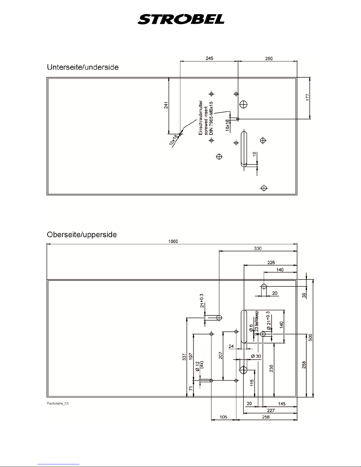
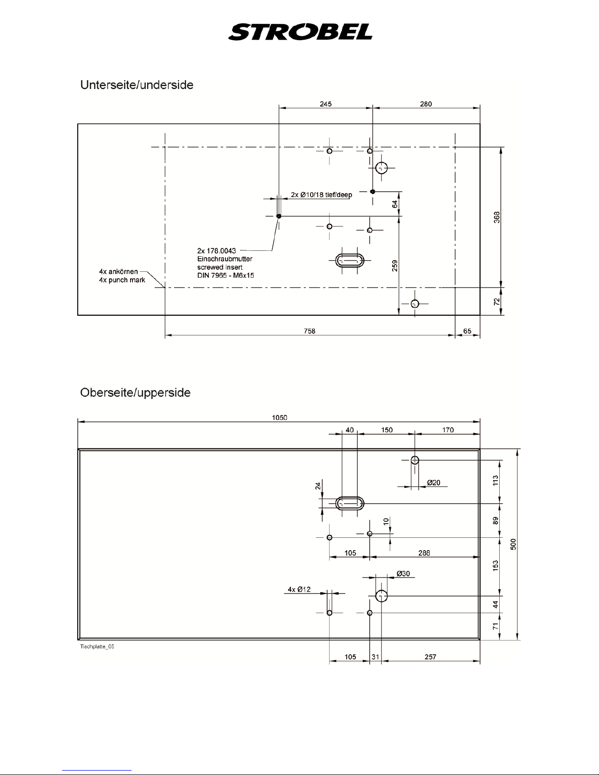
If the machine head is supplied without stand and motor first make the borings
into the table top as shown in the drawing. Mount rods and treadles and electric
connections according to the connecting diagram.
Mount the motor. Electric connection as per connecting diagram shown in the
motor's operating instructions.
The upper component must be fastened to the provided rubber plate on the
table top. The belt guard must be installed after inserting the V-belt.
Mount the V-belt and tense it according to “3.4.1 Tensioni ng the V-belt“.
Mount the belt guard.
Mount the lifting and motor operating rods.
Using a compact motor means to assemble the control box and speed controller
under the table. Also the operating rod between speed controller and pedal has
to be connected.
After assembling the single parts of the reel stand mount it to the right hand side
of the tabletop.
Make sure that all screws on the stand are tight and retighten them, if
necessary.
Mount the synchronizer and set it as described under “3.4.2 Positions of the
machine“.

10 BA_VEB100-1-2-2W-4-5_A3-1_180615_en
CAUTION! Danger of injury!
Before starting the machine, check that the electrical
specifications given on the type plate of the motor,
particular grid voltage and frequency, are appropriate for
your electric system.
Any anti-rust substances, such as vaseline or similar, must be carefully
removed from the sewing tools before starting up the machine.
11 BA_VEB100-1-2-2W-4-5_A3-1_180615_en
3.3
When facing the handwheel, turn it in a clockwise direction.
Direction of rotation on machi ne
3.4
3.4.1
Motor drive via V-belts
Tensioning the V-belt
Caution! Danger of injury!
When checking the belt tension, switch off the machine at
the mains. Do not operate the machine without the belt
guard. Otherwise there is a DANGER of crushing
fingers, of injuries to the body and of pulling in parts of
clothing.
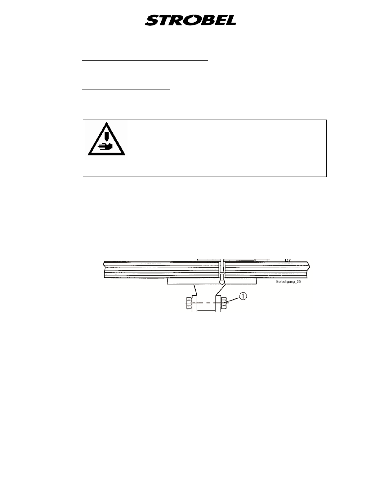
The tensioning of the V-belt is carried out by swivelling the motor underneath
the table plate after releasing the retaining nut with SW 24, (1) in Fig. 1.
The V-belt must not be tensioned too much, especially with the stop motor. You
should be able to compress it with light thumb pressure by about 2 cm.
Too little V-belt tensioning can impair the positioning of the machine and
therefore impair the function sequence.
Fig. 1
12 BA_VEB100-1-2-2W-4-5_A3-1_180615_en
3.4.2
Positions of the machine
Caution! Danger of injury!
Danger of crushing fingers and needle through stitching as
well as pulling in of parts of clothing.
Keep fingers and hands away from moving parts when
setting the position generator and checking the positions
with switched-on mach ine.
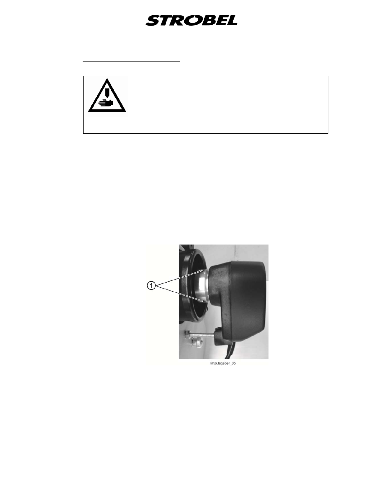
General:
Stop motors require a position generator, which takes the mechanical setting of
the machine from the main screw and transmits this to the control o f the mot or .
With this, for instance, the thread cutter can always be electrically approached
in exactly the same needle looper position. (Fig. 2)
The correct position of the position generator to the flange is marked with a spot
of paint.
To adjust or to remove, release the two clamping screws (1), Fig. 2 tighten
these firmly prior to commissioning.
Fig. 2
With positioning wi th plunger reset, the motor reverses after thread cutting for a
certain value, to facilitate the insertion of the sewing matter. This does not affect
the setting of the position generator.
13 BA_VEB100-1-2-2W-4-5_A3-1_180615_en
Machine with or without thread cutter:
The machine requires a needle position and, depending on the sewing drive,
possibly also a reference position.
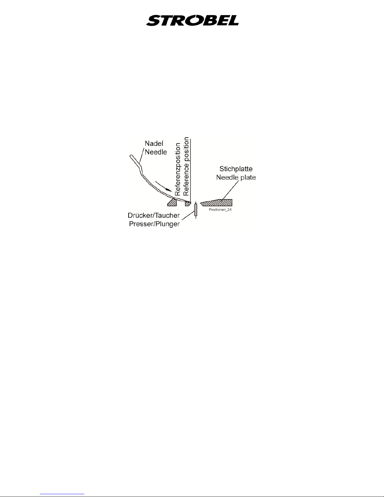
Reference position (Fig. 3):
The reference position must be set in such a way, that the point of the
needle in the direction of the insertion stitch closes with the right (inner)
edge of the needle slide plate.
Fig. 3
14 BA_VEB100-1-2-2W-4-5_A3-1_180615_en
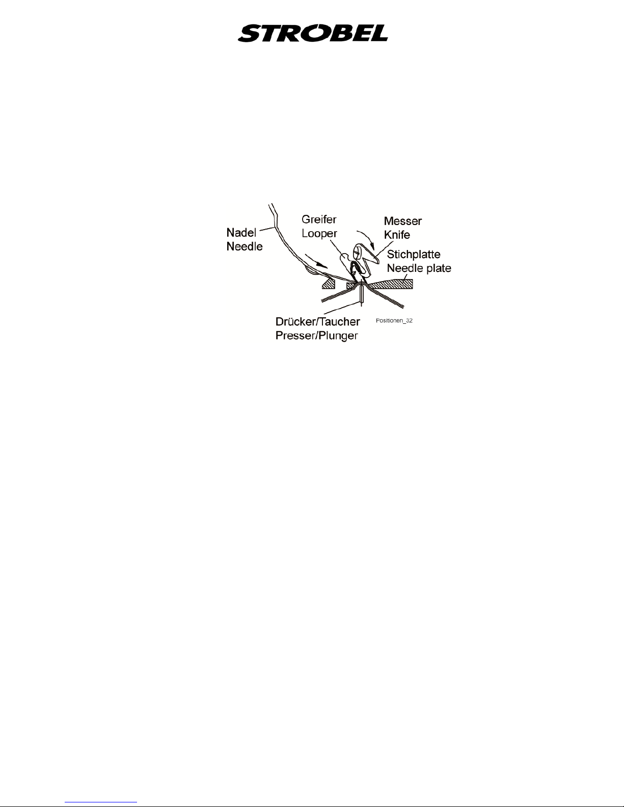
Needle position (when stopped within and outside of the stitch (Fig. 4))
(when using a thread trimmer):
Adjust the needle position so that when the machine is switched off, the
hook of the thread blade can reliably catch the thread loop above the
looper without touching it.
In conclusion, check this by manually actuating the thread trimmer.
Fig. 4
Notes for sewing drives with more than needle positions:
The needle position given above is suitable for sewing at position 2.
It is very important to set position 1 in accordance with the operating
instructions pertaining to the chosen mode of sewing.

15 BA_VEB100-1-2-2W-4-5_A3-1_180615_en
3.5
3.5.1
Motor drive using tooth belts
Tension of toothed belt (Fig. 5 )
CAUTION! Danger of injury!
Switch off the machine at the mains when checking the
belt tension. Do not operate the mac hi ne w it hout bel t
guard. Otherwise DANGER of crushing fingers, of injuries
to the body or of pulling in of part of clothing.
The toothed belt should not be tensioned too much. You should be able to push
through it with light thumb pressure by about 5 mm.
Too little or too tight toothed belt tensioning can impair the positioning of the
machine and therefore impair the function sequence.
Tensioning the toothed belt (Fig. 5):
- Release the upper and the bottom retaining screw (1), (2) at the upper part
of the machine.
- Pull out the motor slightly and tighten the bottom retaining screw (2)
slightly.
- Tension the toothed belt by swivelling the motor.
- Tighten the upper and the bottom retaining screw (1), (2) again.
Fig. 5

16 BA_VEB100-1-2-2W-4-5_A3-1_180615_en
3.5.2
Machine positions
CAUTION! Danger of injury!
Entanglement hazard for clothing or hair and danger of
finger injuries and needle punctures! When checking the
positions while the machine is turned on, keep your
fingers and hands away from moving parts.
Machine with or without thread trimmer:
The machine requires a needle position and depending on the sewing drive,
possibly also a reference position.
Reference position:
The reference position must be set in such a way, that the point of the
needle in direction of the insertion stitch closes with the right (inner) edge
of the needle slide plate.
Needle position (with stop in and outside the seam (Fig. 4)):
The needle position must be set in such a way, that when the machine is
stopped, the hook of the thread knife catches the thread loop lying over
the looper securely without touching the looper.
Notes for sewing drives which have two needle positions:
The above mentioned needle position is position 2 at the sewing drive.
It is essential that position 1 is set with consultation of the operating
instructions of the sewing drive
Needle position (when stopped within the stitch):
The needle position must be set so that the tip of the needle closes
against the right edge of the needle slide plate facing towards the outward
stitch.
At the same time, the thread loop lies under tension across the looper.
The needle position is position 1 at the sewing drive.
Fig. 6

17 BA_VEB100-1-2-2W-4-5_A3-1_180615_en
4
4.1
Notes on usage
The sewing quality can be improved by using the most appropriate needles and
threads for the goods to be produced.
Needles and threads
Only use approved GROZ-BECKERT needle system 1669 EEO.
The machine is delivered with needles of size 70 (VEB100-4),
80 (VEB100-1, -2, -5) and 90 (VEB100-2W).
Note: An intact needle is very important for ensuring good quality stitches.
Bent needle tips, that may only be visible under a magnifying glass,
will lead to poorer sewing results. Replace your needles in time!
We recommend using tw ined polyester tread of thickness 120 /2
(VEB100-1, -2, -2W, -5) and 200 (VEB100-4). Due to their high strength and
good sliding behaviour at a small thread size, they are preferable to spun thread.
Guarantee note!
This machine has been configur e d and br ok e n in usi ng
original GROZ-BECKERT needles.
No guarantees can be given when the machine is
readjusted for the use of different needles.
4.2
Inserting the needles
CAUTION! Danger of injury!
Before replacing needles, switch off the machine and
push down the motor switch pedal to ensure that the
machine is truly switched off.
Otherwise there is a danger of finger injur i es and nee dl e
punctures.
The bent shape of the needles determines the position of the needle lever. Only
ensure that the needle shank can be pushed into the groove of the needle lever
until it stops and the needle clamping plate is tightly fastened using the screw
((for pos 4) Fig. 7).

18 BA_VEB100-1-2-2W-4-5_A3-1_180615_en
Fig. 7

19 BA_VEB100-1-2-2W-4-5_A3-1_180615_en
4.3
Threading and thread inser t ion
CAUTION! Danger of injury!
Before threading, switch off the machine and push down
the motor switch pedal to ensure that the machine is truly
switched off.
Fig. 8 indicates the correct threading using the thread take-up device
Fig. 8

20 BA_VEB100-1-2-2W-4-5_A3-1_180615_en
4.4
Depending on the quality, configuration and thickness of the thread as well as
the sewing material, the thread tension is set using the knurled nut
Thread tension
((2) Fig. 7)
until the desired seam shape is created (Fig. 11).
4.5
The thread take-up lever
Thread take-up lever
(8) shown in Fig. 7 prevents the thread from twisting
and the loop from collapsing. It also ensures that the loop is properly caught by
the looper and needle.
The seam shape becomes homogeneous and the edge of the hem free of
tension.
The behaviour of the thread take-up lever is affected by the thread mov em ent
(choice of eye) and thread tension.
4.6
The stitch depth controller makes it possible to adjust the distance between
the upper edge of the plunger and the needle radius so that the plunger is lifted
or lowered, depending on the thickness of the material to be sewed. This
determines how deep the needle can penetrate into the layer of material
between the plunger and cloth retainer. This value is referred to as the stitch
depth.
Stitch depth control
4.6.1
The stitch depth is set using the control button
Adjusting the stitch depth
((5) Fig. 7) and is located on the
front side of the machine.
Turn the control button to the left (+) to create a deeper stitch.
T urn the control button to the right (-) to create less stitch depth.

21 BA_VEB100-1-2-2W-4-5_A3-1_180615_en
4.7 Cloth retainer (Fig. 9)
CAUTION! Danger of injury!
When making adjustments in the needle plate area, there
is an injury hazard for fingers due to accidental actuation
of the pedal s!
The needle plate is equipped with a cloth retainer. This retainer holds the
sewing material against the plunger to allow needles to insert stitches.
The cloth retainer must be set so that the sewing material cannot move as the
needle inserts stitches.
The correct positioning is important for the quality of the stitch! The pressure
of the cloth retainer against the layers of material or seam edge can be varied
by turning the screw ((1) Fig. 9a and Fig. 9b). This should be kept as small as
possible
to prevent the material from developing tension or becoming marked by the
pressure between the plunger and cloth retainer. This is particularly important
with delicate materials such as velvet.
However, the pressure must still be sufficient to ensure that the sewing material
cannot move during the needle insertion.
The cloth retainer in machines equipped with a spring-loaded plunger is
combined with an adjusting screw which limits the cloth retainer's upwards
stroke. This combination is called plunger limit stop. Plunger limit stop and the
spring-loaded plunger prevent the needle from stitching through the material
over cross seams and other thicker parts and avoid markings.
The Cl.VEB100-5 (Fig. 9d) has no real cloth retainer. During the time of ne edle
penetration the material is hold between folder (1) and plunger (2).
The pressure of the folder on the fabric layers should be as low as possible to
avoid any twist or marks.
This is of main importance for delicate fabrics such as e.g. velvet.
Adjustment by turning knur l ed nut (3), depending on the set stitch depth.
The folder should be set in a way that the fabric cannot move during needle
penetration.
This setting is of great importance with regard to the sewing quality!
Correct folder setting please see “5.3.2 Sewing with folder“.
22 BA_VEB100-1-2-2W-4-5_A3-1_180615_en
Fig. 9
a Cl. VEB100-1, -2
b Cl. VEB100-2W
c Cl. VEB100-4
23 BA_VEB100-1-2-2W-4-5_A3-1_180615_en
d Cl. VEB100-5
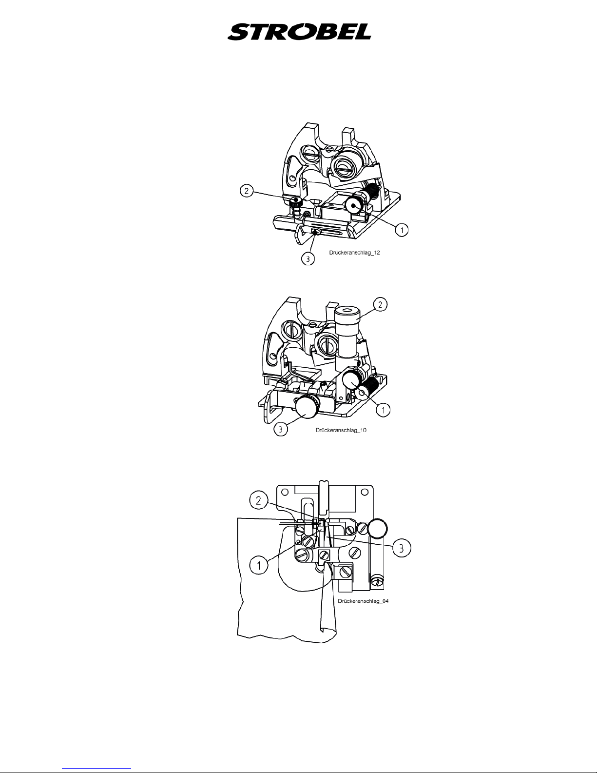
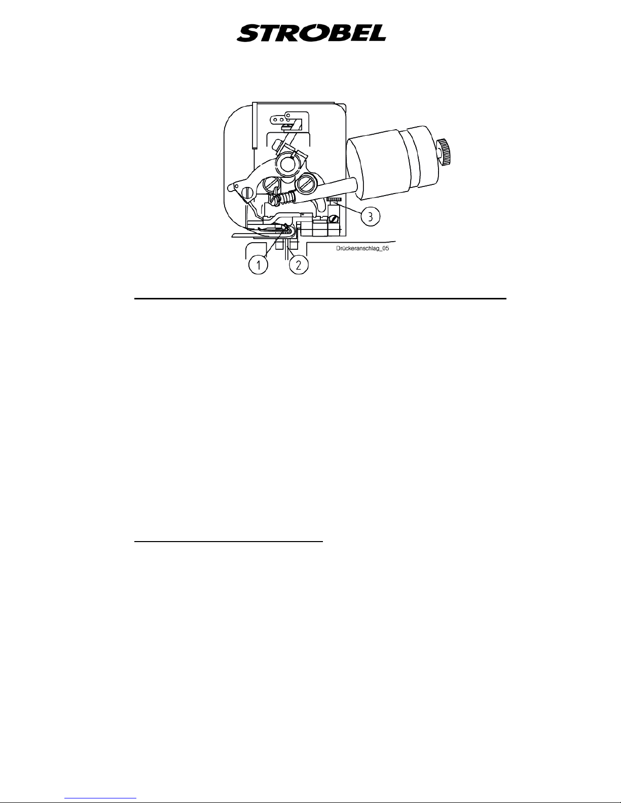
4.7.1
The cloth retainer stroke is set by means of a knurled nut (2)
Setting the plunger limit stop for sewing over cross seam s
Fig. 9a and
Fig. 9b, which serves as upper limit stop. To set the stroke place the material (a
normal fabric layer without cross seam). Close the cloth support arm and turn
the hand wheel manually until the needle penetrates the fabric. In this position
there should be nearly no space between cloth retainer and fabric layer. If the
setting is correct the automatic plunger should be compensating the over cross
seams, so that the needle does not penetrate the outer layer.
The pressure of the cloth retainer on the fabric layers or the hem edge can be
adjusted through turning the knurled nut (1) Fig. 9a and Fig. 9b. The pressure
should be as low as possible to avoid twist or marks resulting from the pressure
between plunger and cloth retainer, mainly when sewing delicate fabrics as e.g.
velvet. However, the pressure should be high enough to keep the material
between plunger and cloth retainer during the time of needle penetration.
The setting of the plunger limit stop has a considerable influence on the stitch
quality.
4.7.2
The spring pressure of the automatic plunger is set at works and usually needs
not to be altered. If the plunger limit stop is set correctly over cross seams the
needle should not penetrate the outer fabric layers.
Setting the automatic plunger
For plunger settings please refer to the mechanic's instructions.

24 BA_VEB100-1-2-2W-4-5_A3-1_180615_en
4.7.3
The Cl. VEB100-4 is equipped with an additional cloth retainer made of a spring
plate (1),
Setting the cloth retaine r Cl. VEB100-4
Fig. 9c, that holds the sewing material firm on the one-sided bevelled
plunger (2) with the roll seam nozzle (3) for the piercing of the needle (Fig. 9c).
The pressure of the cloth retainer on the sewing material is specified by the
shape of the cloth retainer plate.
The cloth retainer is screwed fast to the needle plate and needs to be set so
that the sewing material cannot be shifted while the needle pierces.
The correct setting has a significant influence on the quality of the stitch.
For correct setting of the seamer, refer to point “5.3.2 Sewing with folder".

25 BA_VEB100-1-2-2W-4-5_A3-1_180615_en
4.8
The machine transports the sewing material using a rigid upper transport. The
feed (stitch length) can be set from 5-8 mm (corresponds to 2-5 mm with the Cl.
VEB100-4) in 4 steps. Serially, a pyramid-toothed (saw-toothed for C l . VEB100-
4) feed dog is mounted, which can be exchanged for a saw-t oothe d one
(pyramid-toothed) if necessary. (see point „
Sewing material transport
7 Variable sewing tools“).
4.8.1 Adjusting t he s t itch length
CAUTION!
Switch off the machine and push down the motor switch
pedal to ensure that the machine is truly switched off.
Press the stitch setting knob ((1) Fig. 9) and turn the handwheel until it simply
snaps into place. The config ur ed stit c h le ng t h corr esp onds to the number
engraved in the handwheel as it comes to a standstill in the highest position.
Press down the setting knob and move the handwheel forw ar ds until the
desired stitch length noticeably snaps into place.
4.8.2
The feed dog can be adjusted in its intrusion depth to the needle plate by
loosening the two fastening screws. If the stitch length is adjusted across a
greater range e.g., from 8 to 5 (from 5 to 2 on Cl. VEB100-4), then the feed dog
should be readjusted.
Adjusting the upper feed dog
Adjustments might also be required when changing to sewing materials that are
thicker or otherwise different in quality.
Here, observe the instructions giv en in the me chani c' s manual .

26 BA_VEB100-1-2-2W-4-5_A3-1_180615_en
4.9
The machine is equipped with a shiftable interval 1:2.
Interval (Cl. VEB100-1, -2, -2W, -4)
The interval principle is based on recurrent lowering of the plunger to an exactly
configured value (interval stitch depth).
When switched on, the outer layer of material is only stitched every second time.
This usually makes it possible to create a marking-free, elastic seam in
materials that are difficult to sew.
4.9.1
The interval stroke (= lowering of plunger) defines the stitch depth during the
“interval stitch”.
Activate and a djusting the interval
To switch on the interval for a correctly configured stitch depth, screw in the
control knob ((6) Fig. 7) until the required interval stroke is achieved.
More stroke means a less stitch depth and vice versa.
4.10
General:
Motor
A stop motor (DC 1200) is available for driving the sewing machine.
A needle positioning motor is needed for an exact machine positioning and to
operate the electromec hanic al thr ea d tri m mer and pne umatic lifting.
Please observe the operating instructions of the sewing drive supplied with the
machine where you will find instructions to program the control and the motor
speed.

27 BA_VEB100-1-2-2W-4-5_A3-1_180615_en
4.11
4.11.1
Seam lock (version RF)
The classes VEB100-1, -2 and -2W can be equipped with seam lock and than
they are named: VEB100-2RF.
General
4.11.2
The parameter F-10 m ust be set from 0 to 1.
Switching on the seam lock
CAUTION!
Under no circumstances may the LED 4 light up during sewing operation.
4.11.3
The "simple" backtack sequence is used for technical control in these machine
classes.
Seam lock
Sequence:
The seam lock is made at the seam end by lifting the feed dog.
1. After sewing pedal in position 0, the machine stops in position 1. (Fig. 10)
2. Pedal into position 2 means the second thread tension close, the plunger
drops down and the feed dog lifts up.
3. The machine makes the seam lock stitches with slow speed (normally 3
stitches) and stops in position 1. The second thread tension, the plunger
lift and the feed dog lift switch off now.
4. The machine turns to position 2 and cuts the thread.

28 BA_VEB100-1-2-2W-4-5_A3-1_180615_en
4.11.4
The additional thread tension should pull close the loop of the seam lock when
switched on.
During normal sewing it is lifted by a pneumatic cylinder and is out of operation.
Thread tension at seam lock
4.11.5
The feed dog is lifted up by a pneumatic cylinder at the seam lock. It now glides
gently over the sewing material during the transport movement without
transporting it further.
Feed dog at seam lock
4.11.6
The lowering of the plunger at the seam lock prevents a punctuation of the outer
fabric.
By turning the knurled screw at the pneumatic cylinders under the table top the
height of the lowering can be changed.
Plunger lowering at seam lock
Turn to right - : Lowering is increased
Thick sewing material Stitch depth becomes less
Turn to left + : Lowering is reduced
Thin sewing material Stitch depth becomes greater
4.11.7
The parameter F-10 m ust be set from 1 to 0.
Switching off the seam lock

29 BA_VEB100-1-2-2W-4-5_A3-1_180615_en
5
It is recommended to equip the machine with a pneumatic lifting device to
facilitate machine handling (please see “
Operating the machine
8.4 Pneumatic lifting”).
ATTENTION!
Please observe the sewing area carefully during sewing.
Otherwise danger of finger bruises and needle through
stitches.
5.1
Connect the compressed-air conditioner to the compressed air supplier (max.
10 bar) or to the compressor and set it to 6 bars. Switch on main switch on the
right hand side under the table top, control lamp in the "OFF" switch lights red.
On machines with pneumatic lifting now the material support arm is open, the
machine is ready to sew.
Switching on
5.2
a) treadl e lifting
Placing and removing the fabric - sewing process
By pressing the left hand treadle the cloth support arm is lifted.
Place material under the needle plate and leave the left hand treadle. The
machine starts sewing by operating the right hand treadle.
The machine runs at maximum speed when the right hand treadle is
completely pressed down (please see “4.10 Motor“).
b) pneumatic lifting (optional extra)
Fig. 10 shows the treadle's switching functions when the machine is
equipped with pneumatic lifting. Place the fabric under the needle plate
while the cloth support arm is lifted and close the arm by slightly pressing
the treadle (+1).
The machine is now ready to sew.
If the fabric is not placed correctly, the cloth support arm can be lifted
again by heeling the treadle back into its initial position. At the end of the
sewing process the thread trimmer (optional extra) is operated and the
cloth support arm is lifted by heeling the treadle (-1).

30 BA_VEB100-1-2-2W-4-5_A3-1_180615_en
Fig. 10
5.3
The machines of the VEB100 series are mainly designed for blind stitch
hemming. The special applications of the corresponding subclasses are
described under “
Sewing
2.3 Applications of the machine”.
The sewing result should be an elastic seam free of marks. Depending on fabric
quality the sewing requires a certain skill. The following instructions will help the
operator to obtain this skill.

31 BA_VEB100-1-2-2W-4-5_A3-1_180615_en
5.3.1
In situations where no previous experience has been gathered, use sequence
as below:
Seams with blind stitches
1. Set the desired stitch length. Fig. 11 displays the corresponding seam
shape for the required stitch length.
2. Set the stitch depth.
3. Check the cloth retainer pressure and adjust it if necessary.
4. Adjust the plunger stop.
5. Adjust the material guide as desired. To do this, loosen the screw (3)
Fig. 9 and move the material guide to find the limit for the edge of the
seam.
Sewing can be performed along the edge or directly on the hem. For more,
see Fig. 12
6. Cl.VEB100-4, -5 check the folder setting and adjust it, if necessary.
7. Check the stitch length; if necessary readjust the feed dog.
8. Adjust the thread tension. As a rule, the seam should be loosely on the
seam.
9. If desired, switch on the interval and set the interval stroke according to
the required thickness of sewing material.
10. To correct the seam shape, thread in at a different spot if necessary.
To place in the sewing material and ensure that the start of the seam can be
caught by the feed dog a fter the first stitch.
Press the pedal briefly. Sew the part and, if required, changes the previous
settings until the desired sewing results are achieved. When stitching through
the outer material, readjust the stitch depth control.
On extremely thin or hard sewing material, it may not be entirely possible to
prevent “markings” caused by the penetration of needles into the outer material
(filament displacement).
When sewing, ensure that the edge of the seam always runs along the material
guide. Avoid sudden actuation of the pedal since the speed changes can have
a negative effect on stitching during the sewing process.

32 BA_VEB100-1-2-2W-4-5_A3-1_180615_en
Fig. 11
Fig. 12
5.3.2
Folder (Cl.VEB100-5)
Sewing with folder
The machine is equipped with a special combination of needle plate and folder
to provide side and back parts of sack coats with a uniform book seam.
Folders with a width of 6, 8 and 10 mm (finished hem width after pressing) are
available.
The standard machine is equipped with folder 286.0364, size 6x1 for thin to
medium material.
Roll seamer (Cl. VEB100-4)
The needle plate is equipped with a special material guide (roll seamer) that
"rolls in" the sewing material at the edge during the running into the needle plate.
The roll seamers No. 0, 1, 2, roll diameter are available for thin medium, thick
material and and the Special roll hemmer for sewing curves.
Serially, the standard roll seamer 286.0428, size 1, has been mounted and set
for medium sewing material.

33 BA_VEB100-1-2-2W-4-5_A3-1_180615_en
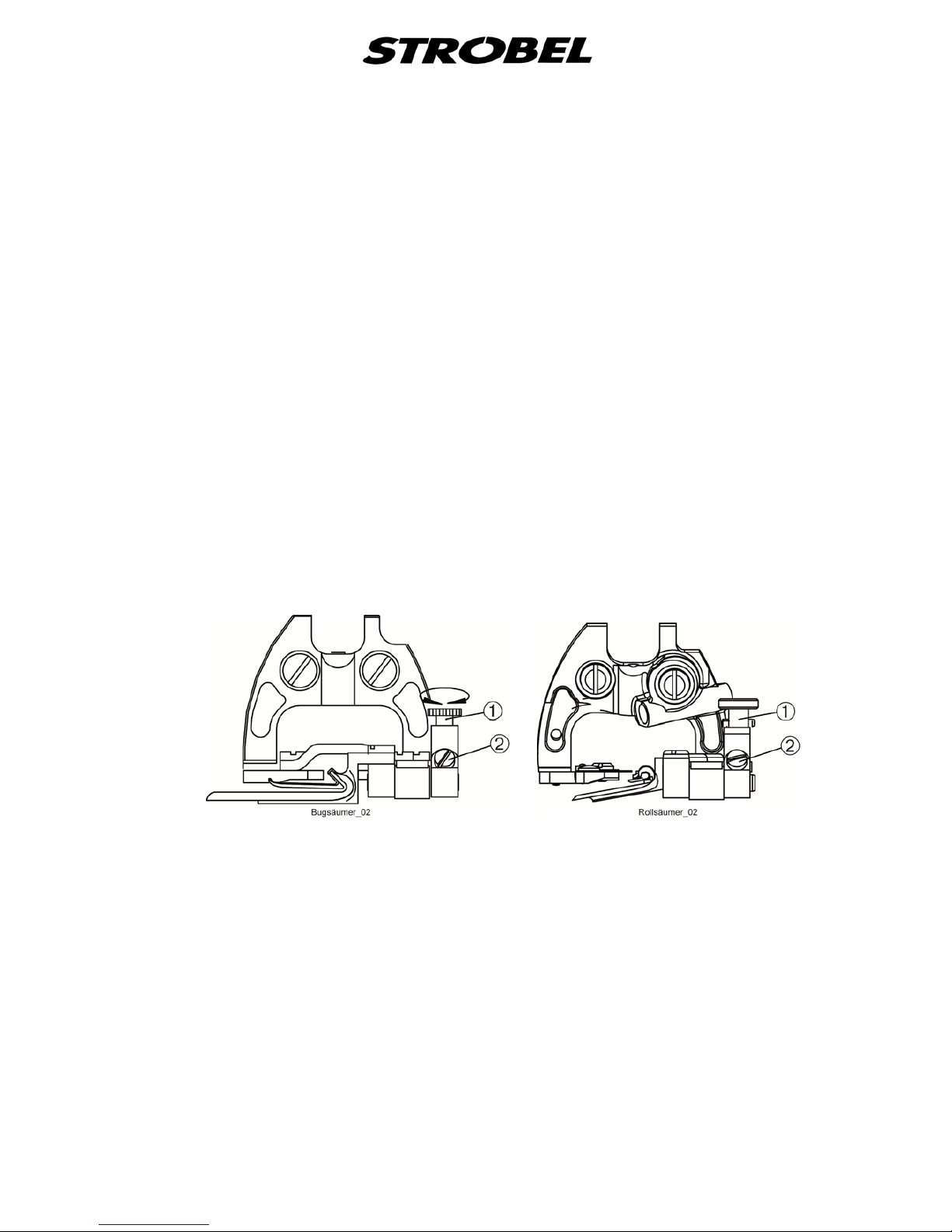
5.3.2.1
Folder (Cl.VEB100-5)
Setting the folder
To re-adjust the folder, the angle of inclination can be adapted to the fabric
thickness by means of knurled screw (1) (Fig. 13a and Fig. 14a). The folder
should be placed downwards until one fabric layer is nearly jammed between
the lower side of the folder and the plunger (Fig. 13).
The folder can be set horizontally after loosening screw (4) (Fig. 14a). This
adjustment becomes necessary when a folder is replaced by another one or if
the seam appearance has to be modified.
According to the adjustment the seam can either be placed on the hem edge
(Fig. 15a) or under the hem edge (Fig. 15b).
Being the thread tension set correctly the overseam should be half as wide as
the hem (Fig. 15c).
After re-adjustment of the horizontal folder setting the inclination angle of the
folder has also to be re-adjusted as described above.
If a fine adjustment by means of the knurled screw is not possible any more, a
coarse setting after loosening screw (2) (Fig. 14a) is necessary. Then the shaft
has to be clamped again without any lateral play. If necessary, after releasing
three screws (3) (Fig. 14a) the complete bench with folder can be slightly
displaced on the needle plate.
34 BA_VEB100-1-2-2W-4-5_A3-1_180615_en
Roll seamer (Cl. VEB100-4)
Using the knurled screw (1) (Fig. 13b and Fig. 14b), the tilt angle of the roll
seamer towards the plunger can be set.
This influences the seam diagram (zigzag stitch). The needle can pierce the roll
more or less deeply.
This setting is the most important control together with the stitch depth
regulation during roll seaming.
The horizontal setting is done after loosening the screw (4) Fig. 14b. This is
necessary when the seamer is exchanged for a different one, or if the seam
diagram should be changed.
If the horizontal setting of the seamer was changed, the seamer tilt angle needs
to be corrected again afterwards as described above.
If the range for the knurled screw is exhausted, then the rough setting can be
redone after loosening the screw (2) (Fig. 13b and Fig. 14b. Afterwards, the
axle needs to be clamped again without lateral play. If necessary, the entire
bearing block with seamer can be slightly adjusted on the needle plate after
loosening the 3 screws (3) Fig. 14b.
Fig. 13
a b
Cl. VEB100-5 Cl. VEB100-4

35 BA_VEB100-1-2-2W-4-5_A3-1_180615_en
Fig. 14
a b
Cl. VEB100-5 Cl. VEB100-4
Fig. 15
a b c
5.3.2.2
Loosen screw (4) (
Replacing the folder
Fig. 14), mount and tighten the new folder.
Realise settings as described in “5.3.2.1 Setti ng the folder “.
5.3.2.3
When the material support arm is lifted place the material from the left side and
push the folded corner under the feed dog ' s front edge. The machine should be
switched on and should have positioned at least one time (stop motor). The
seam starts approx. 1 stitch length behind the fabric edge. When using the
standard 6 mm folder a stitch length of 7 mm is recommended.
Hemming with folder (Cl.VEB100-5)
During the hemming operation the hem edge should always run along the upper
folder edge. As a guide serves opening (5) in (Fig. 14).

36 BA_VEB100-1-2-2W-4-5_A3-1_180615_en
5.3.2.4
The machine should be switch on and have positioned at least once (stop
motor).
Seaming with roll seamer (Cl. VEB100-4)
The sewing material is inserted into the roll seamer from the left side whilst the
material support arm is lifted. Pull the material diagonally forwards to under the
feed dog. A rolling should be done thereby manually in the roll seam nozzle.
Pull back the sewing material so that the feed dog can catch it. Close the
material support arm. The beginning of the stitch is then about 1 stitch length
behind the edge of the material.
During the sewing, the seam edge needs to be guided by hand evenly along the
seamer infeed (3) Fig. 14b.
Of advantage is to turn the material counter-clockwise (Fig. 16) during the
sewing.
Fig. 16
37 BA_VEB100-1-2-2W-4-5_A3-1_180615_en
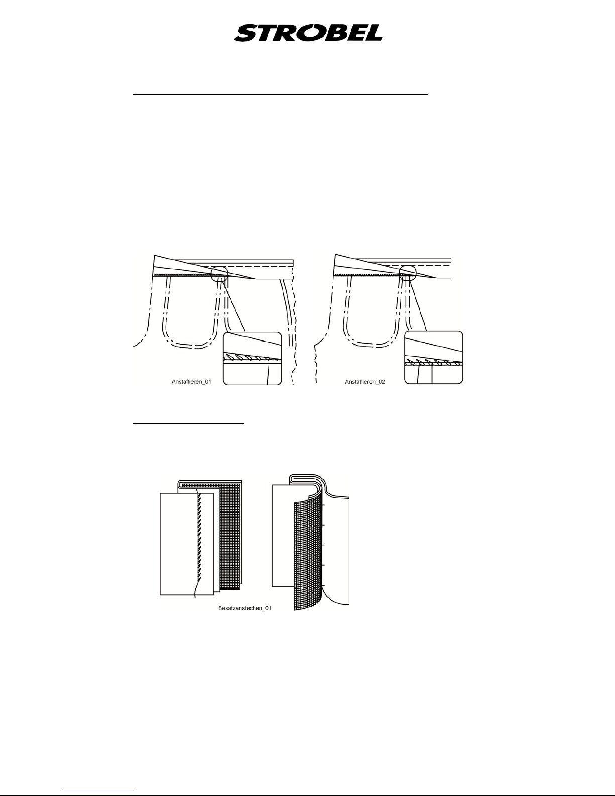
5.3.3
For this operation a needle plate with wide opening is recommended since
usually different fabric layers have to be sewn.
Attaching the trouser waistband lining (Fig. 17)
Recommended needle sizes: 80, 90
There are two different types of operations (Fig. 17a and Fig. 17b):
a) sewing the waistband on the lining
b) sewing the waistband on the edg e
Fig. 17
a b
5.3.4
This operation is shown in
Attaching facings
Fig. 18.
Fig. 18

38 BA_VEB100-1-2-2W-4-5_A3-1_180615_en
5.4
Sewing problems and troubleshoot ing
CAUTION!
Switch off the machine and push down the motor switch
pedal to ensure that the machine is truly switched off.
Otherwise there is hazard of finger injuries and needle
puncture!
Thread breakage
Possible causes:
- Sharp edges or grooves in the needle guide, thread take-up lever,
looper
or needle’s eye after the machine has been used for a long time.
- Looper or loop stroke incorrectly adjusted or has been moved, the
thread loops are not always caught.
- Thread tension is too hi g h
- Thread thickness does not correspond to the needle thickness
(thread too thick)
Solutions:
- Replace or repolish the damaged parts
- Correct the looper setting and/or loop stroke
- Correct the thread tension, check the thread movement.
- Choose a suitable thread thickness
Always observe: Thread movement, thread, needle plate with
corresponding plunger and cloth retainer, tested
needles and thread tension must correspond to the
sewing material being processed!
Imprecise blind stitching
Possible causes:
- Often worn or damaged needle
- Cloth retainer or setting is incorrect
- Needle plate or needle guide is incorrectly set
- Center needle guard damaged or worn
- Needle thickness is not suitable (t o thi n)
- Damaged or incorrectly adjusted plunger
Solutions:
- Replace any damaged needl es , use t he cor r e c t needl e thickness
- Check the settings and correct if necessary
- Replace the center needle guard

39 BA_VEB100-1-2-2W-4-5_A3-1_180615_en
Skip a loop
Possible causes:
- Incorrectly adjusted looper
- Loop stroke/needle stroke incorrectly adjusted, therefore loop size
(too small/too large) may not be suitable
- Chaining finger damaged or altered
- Incorrectly set or altered cloth retainer or cloth retainer pressure
Solutions:
- Rotate the machine by hand, check the looper movement; usually the
cause can be seen.
- Check the settings, correct if necessary and/or replace any damaged
parts.
- If necessary, change the threading at take-up
The machine does not start even though the indicator lamp of the
main switch is on.
Possible causes:
- Thread trimmer not in final position, microswitch is locked
- Control box error
- Mechanical damage, machine is blocked
Solutions:
- Turn the machine off and back on again. Check the cutting position
of the blade. Check the programming
- Eliminate any mechanical faults and, if necessary, call the customer
service.
Markings or damage to the sewing material
Possible causes:
- Feed dog gearing is not suitable
- Plunger shape is not suitable for the sewing material
- Cloth retainer, pressure is set too strongly
- Presser foot pressure has been incorrectly adjusted or lift-off is
blocked.
- Damaged sewing parts (lower side of needle plate!)
- Needles or thread thickness not suitable
Solutions:
- Replace the feed dog or plunger
- Check the press er foot , sewing parts and their functionality, replace
any damaged parts and/or repolish them if necessary.
- Choose needles and threads that are suitable for the sewing material

40 BA_VEB100-1-2-2W-4-5_A3-1_180615_en
Difficulties in feeding the sewing material
(stitch lengths vary from settings)
Possible causes:
- Feed dog is incorrectly adjusted; need to be set lower or higher
- Feed dog gearing is not suitable
- Different presser foot pressure left/right
- Lift-off of presser foot is blocked
- Blockage of sewing material in needle plate, especially for cross-
seams
- The loop remains stuck at the feed dog, for instance.
- Stitch length accidentally altered
- Spring-load plunger blocks at the cross-seam area
- Correct tension on the lower transport belts
Solutions:
- Check the height of feed dog and the stitch length and, if necessary,
replace the feed dog.
- Correctly adjust the pressure of the presser foot
- Check the lower side of the needle plate and feeding/sewing parts for
signs of damage and, if necessary, replace or polish them

41 BA_VEB100-1-2-2W-4-5_A3-1_180615_en
6
The machine is mostly equipped with maintenance free bearings and bushings.
The areas and oil holes marked in red should be re-oiled after 20 operating
hours or at the very latest once per week. One drop of sewing machine oil is
sufficient.
Servicing the machine
To oil looper drive and the feed dog crank, remove the the cover from the head.
Any fabric fibres that collects in the moving parts must be removed on a regular
basis.
7
Variable sewing tools
Attention!
Switch off machine electrically and confirm that the machine
is really in standstill position by operating the treadle for the
motor control.
Otherwise danger of finger bruises and needle through
stitches.
The following chart shows all sewing tools available.

42 BA_VEB100-1-2-2W-4-5_A3-1_180615_en
Cl. VEB100-1
Needle plate
Standard
480.0286
6,0 mm Opening
Optional
480.0287
4,5 mm Opening
Cloth retainer
Standard Optional
188.0243 188.0246
Standard Optional
188.0244 188.0245
Stitch formation
Feed dog
Standard
182.0332
Optional
182.0331

43 BA_VEB100-1-2-2W-4-5_A3-1_180615_en
Cl. VEB100-2
Needle plate
Standard
380.0286
6,0 mm Opening
Optional
380.0287
4,5 mm Opening
Cloth retainer
Standard
188.0243 188.0246
Standard
188.0244 188.0245
Stitch formation
Feed dog
Standard
182.0332
Optional
182.0331

44 BA_VEB100-1-2-2W-4-5_A3-1_180615_en
Cl. VEB100-2W
Needle plate
Standard
480.0257
7,0 mm opening
Cloth retainer
Standard
288.0217
Optional
288.0218
Stitch formation
Feed dog
Standard
182.0331

45 BA_VEB100-1-2-2W-4-5_A3-1_180615_en
Cl. VEB100-4
Needle plate
Standard
380.0275
4,5 mm Opening
Feed dog
Standard
182.0327
Roll hemmer 1
Standard
386.0428

46 BA_VEB100-1-2-2W-4-5_A3-1_180615_en
Cl. VEB100-5
Needle plate
Standard
480.0250
7,0 mm Opening
Folder 6 mm
Standard
286.0364
1,0 mm
Feed dog
Standard
182.0336

47 BA_VEB100-1-2-2W-4-5_A3-1_180615_en
8
The following devices are available as optional extras and can be ordered
together with the machine or as separate kits.
Optional extras
8.1
(not applicable for cl. VEB10 0-4)
Thread trimmer
798.0496 electromechanical thread trimmer
Prerequisite here is use of the
EFKA Kompakt DC 1200 with connection cable
8.2
More hemmer sizes on request.
Hemmer
8.3
(not applicable for cl. VEB100-4)
Digital display 392.0637
8.4
The use of a pneumatic lifting is only recommended if the machine is equipped
with a needle positioning motor.
Pneumatic lifting
8.5
8.6
Seam lock
8.7
Compact drive
Stand set


Und wir können noch mehr für Sie tun!
And we can do a lot more for you!
Unser Lieferprogramm bietet für jede Branche und
jegliche Anforderung genau die richtige Problemlösung.
Our range offers the correct problem solution for
every branch and for all requirements.
Für die Bekleidungsindustrie:
Für die Schuhverarbeitung:
Für die Polsterverarbeitung:
Ein- und ZweifadenHochleistungs-Saummaschinen
DoppelblindstichSaummaschinen
Zweifaden-BlindstichStafermaschinen
Roll- und Flachpikiermaschinen
Pikier-Automat
und
weitere Spezial-Nähmaschinen
Einfaden-Überwendlichmaschinen mit und ohne
Differentialtransport
Ein- und ZweifadenÜberwendlichmaschinen
Ein- und ZweifadenBlindstichmaschinen
For the clothing
industry:
Single and two thread high
performance hemming
machines
Bluff edge hemming machines
Two thread blind stitch felling
machines
Roll and at padding machines
Automatic lapel padding
machine
and other special sewing
machines
For the shoe industry:
Single-thread overseaming machines with and without differential feed
Für Kürschnereien
und Pelzkonfektion:
Pelzschnellnäher
For the fur industry:
High-speed fur sewing machines
Für Heimtextilien:
Ein- und ZweifadenBlindstichmaschinen
For the home textiles
industry:
Single and two thread
blind stitch machines
For the upholstery
industry:
Single and two thread
overseaming machines
Single and two thread
blind stitch machines
Für die Konfektion
technischer Textilien:
Ein- und ZweifadenÜberwendlichmaschinen
For the processing
of technical textiles:
Single and two thread
overseaming machines

Noch Fragen?
Any further questions?
Dann rufen Sie uns an, schreiben Sie uns oder
kommen Sie einfach bei uns vorbei.
Sie können jederzeit weitere Informationen über
unsere Produkte anfodern oder die StrobelNähmaschinen in unserem Ausstellungsraum live
erleben. Wir freuen uns auf Sie!
Then phone, write or simply come and see us. You
can have further information about our products at
any time, or experience the Strobel machines live in
our show room. We’re looking forward to meeting you!
Sp ez i a l ma sc hi n en G mb H
Postfach 1242
82168 Puchheim
Siemensstraße 3
82178 Puchheim
DEUTSCHLAND
www.strobel.biz
Telefon: +49 89 80096-0
Telefax: +49 89 80096-190
 Loading...